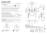
Lefroy Brooks JH 1252 Installation & Servicing Guide
- Category
- Sanitary ware
- Type
- Installation & Servicing Guide

1250 / 1252
FOUR HOLE BATH SET
(SPOUT AND DIVERTER)
INSTALLATION GUIDE


A
A
V1
Ø32mm
G¾ G¾
G¾
V1 V2
V1 V2
60mm
max.
Ø32mm
55mm max.
175mm
Ø57mm
Ø74mm
25mm
Ø45mm
170mm
109mm
40mm max.
750mm maximum
750mm maximum
Ø75mm
215mm
Ø50mm
50mm max.
Ø33mm
207mm
57mm
Ø65mm
104mm
40mm
max.
Ø26mm
60mm
max.
Ø32mm
1500mm long
V2
G¾
A
V1 V2
Ø26mm
1500mm long
1250
1252
A
3
DIMENSIONS

SpoutHandset
10 20 30 40
3.0
2.0
1.0
50
Flow (Litres/minute)
Static Pressure (Bar)
Spout Hand shower
5 10 15 20
3.0
2.0
1.0
25
Flow (Litres/minute)
Static Pressure (Bar)
4
TYPICAL FLOW RATES
Note: Balanced pressures shown are applied directly to the hot and cold inlets; flow rates indicated are
free flowing and may vary subject to restrictions created by installation, pipework, layout or application.
1250
1252
Note: Balanced pressures shown are applied directly to the hot and cold inlets; flow rates indicated are
free flowing and may vary subject to restrictions created by installation, pipework, layout or application.

5
IMPORTANT INFORMATION
Professional installation
We recommend that our products are fitted
by a fully qualified professional plumber. They
should be installed correctly and in accordance
with all local water regulations and the system
protected by non-return valves (not supplied).
All products should be accessible for routine
servicing.
Suits all systems
This Lefroy Brooks product is potentially
suitable for every possible application, type of
boiler and water supply pressure. However,
if your supply pressure is below 1 bar it is
advisable to fit a water pump. For systems with
combination boilers, it is not advisable to fit
pumps (refer to boiler manufacturer).
Supply temperature safety notice
To comply with local building regulations,
current legislation, relevant standards and codes
of practice a thermostatic mixing valve (TMV)
should be fitted (not supplied) to the hot supply.
TMV's are designed to restrict the temperature
to a safe working/maximum temperature.
Maximum allowed temperatures vary subject
to the type of installation or specification of
building.
Balancing flow
If there is a significant dierence in water
pressures between hot & cold supplies, we
recommend an in-line flow suppressor/
regulator (not supplied) be fitted. This should be
fitted to whichever has the greater flow rate, in
an accessible position close to the valve.
Water quality
Limescale (calcium deposits) may eect the long
term performance of ceramic cartridges. In hard
water areas a suitable water treatment system
should be provided to prevent the formation
of limescale. The flow valves, spout and hand
shower should be gently wiped with a dry soft
cloth after use to minimise water stains.
Servicing
All serviceable parts are available to maintain
your Lefroy Brooks product.
General installation details
The diverter requires a minimum static water
pressure of 1.5 bar to retain the diverter knob
in the ‘up’ position (i.e. flow through shower
handset). If the water pressure is lower than 1.5
bar the diverter knob can be lifted and turned
through 90 degrees to lock it into the ‘up’
position.
The four hole bath mixer set is supplied with
suitable flexible hoses. These are to be fitted as
shown in the dimensions drawing. However, the
sequence and the distances can be changed to
suit customer requirements, but any additional
pipework should be supplied by the installer.

6
INSTALLING THE SPOUT/DIVERTER
1 Disassemble the spout and diverter
• There is a set screw located in the diverter
knob. After removing the spout and diverter
assembly from the packaging unscrew the set
screw using the hexagonal key (included) (A).
• Unscrew the diverter knob to remove it from
the threaded rod (B).
• Unscrew the diverter locking nut fully and
remove the diverter from the spout (C).
• Remove the plastic backnut and washer from
the spout, ready for installation (D).
2 Secure the spout
• Locate the spout into the hole in the bath or
worktop (40mm maximum thickness).
• Replace the backnut and washer.
• Tighten the nut to secure the spout in place
(E).
A
B
C
D
E

7
3 Fit the diverter
• Carefully insert the diverter rod assembly
back into the spout (F). It is important to
check that the green fibre washer is still
located inside the locking nut.
Important note:
There are two ‘o’ rings at the top of the plastic
tube. To avoid damage to the ‘o’ rings care
should be taken when passing the rod through
the upper section of the spout. Apply a small
amount of silicon grease to ease assembly.
• Once pushed in fully, tighten the locking nut to
secure the diverter in place (G).
• Continue to install the hot and cold flow valves
and holster. Attach all flexible hoses. Install
the shower hose and handset. The diverter
can be rotated to avoid unnecwessary bends
in the flexible hoses.
• Turn on the water supply and check all joints.
F
G

40mm
maximum
1mm gap
8
4 Setting the diverter
• Before fitting the diverter knob, turn both hot
and cold water supplies on.
• Check that water flows from the spout only.
• Pull the threaded rod upward and check water
flows from the shower handset only.
• Turn the water supplies o.
• The threaded rod will return to the lower
position.
• Screw the diverter knob onto the threaded
rod (H). Leave a 1mm gap (J) between the
spout body and the underside of the diverter
knob. Using the hexagonal key provided
secure the diverter knob in place by screwing
in set screw (K).
Setting is now complete.
• Test the diverter with the water supplies
turned on. Pull the diverter knob up to
operate the handset and push down to
operate the spout.
• Check that the diverter knob returns to its
lower position when the water supplies are
turned o.
• Check all joints before concealing pipework.
Note:
If the static water pressure is lower than 1.5
bar the diverter knob can be lifted and turned
through 90 degrees to lock it into the up
position.
Turn the knob through 90 degrees to release
and return to the lower position.
H
J
K

9
FAULT FINDING
The hot/cold taps are turned o but the spout drips continuously.
• Replace the ceramic cartridge(s). See ‘Replacement parts’ section for spare part numbers.
With the hot/cold taps turned on, water comes from the spout and handset at the same time.
• Follow the setting instructions shown in section 4 ‘setting the diverter’ leaving a 1mm gap between the
spout body and the underside of the diverter knob. If water continues to flow from the spout and handset
at the same time then there may be debris lying on the rubber seal within the diverter.
Water flow from the spout is reduced.
• On 1252 models debris from the water supply may be causing restriction at the aerator located in the end
of the spout. The aerator can be removed for cleaning (see ‘servicing – cleaning the spout
aerator section).
• Check that there are no tight bends in the flexible hoses.
Noisy operation.
• Check that there are no tight bends in the flexible hoses.
• Reduce water pressure.
Leaks from underside of basin.
• Flexible hose joints not tight.
INSTALLING THE FLOW VALVES
Please refer to the separate guide ‘Deck mounted flow valves’ for installation details

Aerator
Washer
Cover
10
SERVICING – CLEANING THE SPOUT AERATOR
1 There is an aerator located in the end of the
spout. To remove this unscrew and remove
the cover in a clockwise direction.
2 The aerator can be cleaned in warm soapy
water.
3 Assemble in the reverse order.
Only applicable on 1252 models

11
REPLACEMENT PARTS
PHL036 – ¾" x ¼ turn ceramic cartridges for levers (pair)
PHL037 – ¾" x ½ turn ceramic cartridges for cross handles/handwheels (pair)
PBS019 – ¾" x ½" braided hoses (pair)
LB2101 – Shower hose
PSH071 – 1250 spout diverter assembly only (May 2016 onward)
PSH079 – 1252 spout diverter assembly only
PSH127 – 1252 spout aerator assembly

Whilst every effort is made to ensure the accuracy of these, they are subject to change without
notice as part of the company’s product development process. The use of trademarks, product design
and artwork is subject to licence or agreement with LBIP Ltd. The design registrations, trademark registrations
and copyrights are protected by law and the use or reproduction outside the terms of an agreement is prohibited.
The right to modify designs and dimensions is reserved. LBIP Ltd is a member of ACID (Anti Copying in Design). E&OE
© LBIP Ltd 2021
CONTRACT ENQUIRIES
+44 (0)1992 708 316
info@lefroybrooks.co.uk
CUSTOMER SERVICE, SPARES & TECHNICAL ENQUIRIES
+44 (0)1902 390 894
technical@lefroybrooks.co.uk
LEFROYBROOKS.CO.UK
20.065.097D / APRIL 2021
-
 1
1
-
 2
2
-
 3
3
-
 4
4
-
 5
5
-
 6
6
-
 7
7
-
 8
8
-
 9
9
-
 10
10
-
 11
11
-
 12
12
Lefroy Brooks JH 1252 Installation & Servicing Guide
- Category
- Sanitary ware
- Type
- Installation & Servicing Guide
Ask a question and I''ll find the answer in the document
Finding information in a document is now easier with AI
Related papers
-
Lefroy Brooks JM 1826 Installation & Servicing Guide
-
Lefroy Brooks XO 5500 Installation & Servicing Guide
-
Lefroy Brooks XO 5115 Installation & Servicing Guide
-
Lefroy Brooks MK 2147 Installation & Servicing Guide
-
Lefroy Brooks XO 4201 Installation & Servicing Guide
-
Lefroy Brooks TL 1110 Installation & Servicing Guide
-
Lefroy Brooks DP 1227 Installation & Servicing Guide
-
Lefroy Brooks DP 1269 Installation & Servicing Guide
-
Lefroy Brooks TL 1188 Installation & Servicing Guide
-
Lefroy Brooks DP 2268 Installation & Servicing Guide
Other documents
-
Bristan Quadrato Tap Range Installation Instructions & User Manual
-
Moen WS84924SRN-8WTR User guide
-
Axor 06110XX0 User manual
-
aquabrass 86013 Installation guide
-
Rohl A3608LMWSSTN-2 Installation guide
-
 Ideal-Standard ALTO ECOTHERM A5638AA Installation Instructions Manual
-
 Arcora AR6100500 User manual
-
Speakman TIBERFULL Installation guide
-
Hansgrohe 31314921 Installation guide
-
Zurn Z831C4-XL-ICT-P Installation guide


