Page is loading ...

Freestanding Direct
Vent Kit With Coupler
KIT COMPONENTS:
Quantity Description Quantity Description
1 Horizontal direct vent termination cap 1 Ø6” (17 cm) 90° elbow
2 Flue collar adapters (only one used) 4 Wire spacers
4 T-20 Torx screws 3 Decorative rings
1 Wall thimble 1 4 oz tube RTV silicone
1 Inside nish trim collar 20 9/16” tech screws
1 5’ (190 cm) length of Ø4” (10 cm) double walled ex pipe 8 1” wood screws
2 24” (61 cm) section of Ø6” (17 cm) straight pipe 1 Vinyl siding deector
Please ensure that all components are supplied with this kit. If components are missing or have
been damaged, contact your dealer, distributor, or courier company. Do not attempt the installation if
components are missing or damaged.
INSTALLATION INSTRUCTIONS:
1. Decide on a location for the unit that will meet any or all local code requirements. Refer to the sections
in your owner’s manual on where to locating your stove, planning your installation and clearances to
combustibles.
2. Set the appliance in the desired location. Determine if any wall studs, electrical wiring, or plumbing
pipes are in the way of the venting system as it passes through the wall. If obstructions are found in
the wall it may be required to adjust the location of the appliance.
3. Set the appliance in the desired location. Temporarily place a 24” (61 cm) section with the non-crimped
end on the unit
4. Install the 90° elbow onto the vertical pipe on the stove pointing in the
direction that the vent will exit the structure.
5. Project a level line from the center point of the elbow. Using this center
point, scribe a 10” (25.4 cm) hole or square on the wall . Cut the hole
out on both the interior and exterior wall surface.
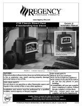
6. Frame the hole as shown in Figure 1.
7. Install the wall thimble and secure the thimble to the inner wall
surface.
8. With the appliance still in place install the 24” (61 cm) horizontal section
on the elbow and let this section of pipe protrude through the exterior
surface. Mark the pipe so that when it is cut it will be ush with the
exterior wall.
9. Dismantle the outer pipe sections. Figure 1
Please read and understand these instructions before installing. Failure to follow
these instructions carefully could cause property damage or personal injury.

10. EG28 or EG40: Remove the 4” (10 cm) ue collar from the unit and remove any loose sealant.
Install the new Ø 4” (10 cm) by 5” (12.5 cm) ue collar provided in this kit.
Westport: Install the 4” (10 cm) adaptor into the exhaust outlet on the unit. Apply a bead of high
temperature silicone.
11. Attach the exible liner to the vent termination cap by placing a small bead of high temperature
silicone on the vent termination and slide the ex liner onto the vent terminal and secure with three
(3) sheet metal screws evenly spaced.
12. Dress the ex liner through the wall thimble and attach the vent
terminal to the outside of the house using four (4) wood screws
provided. The use of non-hardening mastic should be used around
the vent to ensure a watertight seal.
13. Install two (2) wire spacer around the ex pipe. Slide the horizontal
section of pipe over the exible liner. Ensure the wire spacers are
positioned at either end of the pipe (refer to Figure 2 and 3).
14. Install the horizontal section of pipe through the wall thimble,
ensure that this portion of pipe slides onto the vent termination
cap.
15. Slide the inside nished collar over the horizontal section of pipe
and secure to wall using the screw provided.
16. Slide the 90° elbow over the ex pipe. Do not slip the outer
sections of pipe together, you will require some movement
in these pipe section in order to secure the ex pipe to the
ue outlet on the appliance.
17. Stretch the ex liner to a length long enough to ensure the ex
liner can be easily connected to the ue outlet of the appliance.
18. Install the remaining wire spacers over the exible liner and install
the vertical section of pipe. Ensure the wire spacers are positioned
at either end of the pipe (refer to Figure 2 and 3).
19. Place a bead of high temperature silicone on the ue pipe and slide
the ex liner over the collar, secure the ex liner with three (3)
sheet metal screws evenly spaced.
Figure 2
Figure 3
20. Align all straight sections of pipe, slipping all joints
together and installing with three (3) sheet metal
screws evenly spaced.
21. Install the brass decorative rings around each joint
making sure this decorative ring covers the sheet metal
screws that secure each section of pipe together and
secure to vent pipe in the slotted tab on the backside of
the pipe so that the fastener would not be seen.
22. Secure the horizontal section of pipe to the inside
nished collar by installing a screw in the tab on the
inside nished collar. This will prevent the pipe from
being disconnected at the vent terminal.
23. Light the appliance and ensure proper operation.

MANUFACTURED BY:
SHERWOOD INDUSTRIES LTD.
6782 OLDFIELD RD. SAANICHTON, BC, CANADA V8M 2A3
www.envirore.biz
August 11, 2004
C-10561
Part Number Option
EC-061 Freestanding Direct Vent Kit With Coupler
Wall framing
Horizontal wall
termination
Wall thimble
fire stop
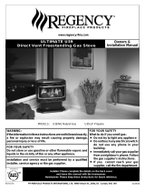
Inside finished collar
Decorative
brass rings
Exhaust 4"
flex pipe
Combustion air
65/8" outer pipe
Flue pipe adaptor
for EG28 and EG40
Flue pipe adaptor
for Westport
Figure 4
/