
WHIP INDUSTRIES, INC.
INSTALLATION, OPERATION &
MAINTENANCE MANUAL
TWO POST ABOVE GROUND
OVERHEAD LIFT
10,000 LBS CAPACITY MODELS
WA102E, WAS102E & WS102E WA102E-12,
WAS102E-12 & WS102E-12
WA102E-18, WAS102E-18 & WS102E-18
WA102E-24, WAS102E-24 & WS102E-24
&
11,000 LBS CAPACITY MODELS
WA112E, WAS112E & WS112E WA112E-12,
WAS112E-12 & WS112E-12 WA112E-18,
WAS112E-18 & WS112E-18 WA112E-24,
WAS112E-24 & WS112E-24
WHIP INDUSTRIES, INC
3010 S MAIN ST.
FORT WORTH, TEXAS 76110
PH (800) 256-7391 FAX (817) 289-1412
E-MAIL: [email protected]
Rev. -

2
2
TABLE OF CONTENTS
Important Information 3
Cautions and Warnings 3
Safety Instructions 4
Anchoring Tips 5
Tools Required 6
Installation Requirements 7
Installation Instructions 7
Inspection and Monthly Maintenance 11
Operation Instructions 12
Trouble Shooting Guide 13
Parts & Shipping List 19
Parts Breakdown and Installation Drawings 24

3
3
IMPORTANT INFORMATION
1. IMPORTANT - Read the installation manual before installing the lift.
2. The floor where the lift is to be installed must be a minimum of 4” thickness of
concrete. Concrete must be reinforced with steel rebar with a minimum compressive
strength of 3,000 PSI. Failure by the purchaser to provide the recommended mounting
surfaces could result in personal injury, property damage and/or unsatisfactory lift
performance. For seismic loads or other requirements, consult a qualified person.
3. This lift is only approved for indoor installation only. Outdoor installation is
prohibited.
4. Read anchoring tips information before drilling and installing the anchor bolts.
5. This lift is an overhead lift which requires a ceiling height of a minimum 12’-0”.
6. Bleed air from hydraulic cylinders before raising vehicle with lift. Air in cylinder
may damage seal.
7. Do not raise a vehicle with the lift until the lift has been correctly installed and
adjusted as described in this manual.
8. Do not remove a suspension assembly, transmission or other heavy item from the
front of a front wheel drive vehicle unless the vehicle is adequately supported in the
rear.
CAUTIONS AND WARNINGS
MOTORS AND ELECTRIC CONTROLS ARE NOT SEALED
AGAINST WEATHER OR MOISTURE. DAMAGE OR ELECTRICAL SHOCK MAY
OCCUR IF INSTALLED UNPROTECTED OUTDOORS.
FACTORY MUST BE NOTIFIED WITHIN 30 DAYS OF DELIVERY
IF THERE ARE ANY PARTS MISSING FROM SHIPMENT.
RECOMMENDED OIL: HYDRUALIC MEDIUM OIL SAE-10 OR EQUIVALENT.
MAY USE TRANSMISSION FLUID DEXRON II OR III ATF.
ALL BOLTS PLACED IN THE COLUMN MUST BE PLACED FROM THE INSIDE
FACING OUTWARD.
TWO POST LIFTS ARE DESIGNED TO PICKUP VEHICLES WITH ALL FOUR
LIFTING PADS ENGAGING THE FRAME OF THE VEHICLE OR DESIGNATED
LIFTING POINT. IT IS VERY DANGEROUS TO PICK UP A VEHICLE USING LESS
THAN THE FOUR LIFTING PADS. LIFTING A VEHICLE INCORRECTLY

4
4
REGARDLESS OF THE WEIGHT OR THE HEIGHT MAY CAUSE BODILY INJURY TO
THE OPERATOR OR DAMAGE THE LIFT AND VEHICLE.
DANGER - RISK OF EXPLOSION
THIS EQUIPMENT HAS INTERNAL ARCING OR PARTS THAT MAY SPARK AND
SHOULD NOT BE EXPOSED TO FLAMMABLE VAPORS. MOTOR SHOULD NOT BE
LOCATED IN A RECESSED AREA OR BELOW FLOOR LEVEL. NEVER EXPOSE
MOTOR TO RAIN OR OTHER DAMP ENVIRONMENTS. DAMAGE TO MOTOR
CAUSED BY WATER IS NOT COVERED UNDER WARRANTY.
IMPORTANT SAFETY INSTRUCTIONS
When using your garage equipment, basic safety precautions should always be followed,
including the following:
1. Read all instructions
2. Care must be taken as burns can occur from touching hot parts.
3. Do not operate equipment with a damaged cord or if the equipment has been dropped
or damaged - until it has been examined by a qualified service person.
4. If an extension cord is necessary, a cord with a current rating equal to or more than that
of the equipment should be used. Cords rated for less current than the equipment may
overheat. Care should be taken to arrange the cord so that it will not be tripped over or
pulled.
5. To reduce the risk of fire, do not operate equipment in the vicinity of open containers
of flammable liquids (gasoline).
6. Keep hair, loose clothing, fingers, and all parts of body away from moving parts.
7. To reduce the risk of electric shock, do not use on wet surfaces or expose to rain.
8. Use only as described in this manual. Use only manufacturer's recommended
attachments.
9. ALWAYS WEAR SAFETY GLASSES. Everyday eyeglasses only have impact
resistant lenses, they are not safety glasses.
SAVE THESE INSTRUCTIONS

5
5
ANCHORING TIPS
1. Anchor must be at least 5” from the edge of the slab or any seam.
2. Use a concrete hammer drill with a 3/4” carbide bit.
3. Do not use a worn bit.
4. Drill in a perpendicular line with the hole.
5. Do not apply excessive pressure to the drill. Let the drill do the work.
6. Lift the drill up and down occasionally to remove residue and to reduce binding.
7. Drill the hole depth equal to the length of the anchor, or completely through the slab.
8. For better holding power, blow all dust and residue from the hole before driving
anchor into hole.
Place a flat washer over threaded end of anchor. Spin nut 1/4” down past end of anchor.
Carefully tap anchor into the concrete until nut and flat washer are against base plate. Do
not use an impact wrench to tighten. Tighten ¾”-10UNC x 5 ½” anchors to 125 ft-lbs. of
torque.

6
6
TOOLS REQUIRED
Concrete rotary hammer drill with ¾” carbide bit
Open End Wrenches: 7/16”, 1/2”, 5/8”, 11/16”, 3/4”, & 1 1/8”
Ratchet Driver
Sockets: 11/16”, 3/4” X 1/2” deep
12” Crescent Wrench
3/16 Allen Wrench
Hammer
Needle Nose Pliers
Electrical Pliers
Level
Fish Tape
25’ Tape Measure
Chalk Line
Small Drift Punch
Step Ladder
3 gallons of hydraulic medium oil SAE-10 or Dexron II or III ATF.

7
7
INSTALLATION REQUIREMENTS
1) Standard lift requires a minimum of 12’ ceiling height. If ordering lift with extension,
then add addition length of extension.
2) Minimum distance required beyond either side of the lift to the nearest obstacle is 6”
3) Minimum of 8’-0” is required in front of the lift to the nearest obstacle.
4) Minimum of 12’-0” is required in the rear of the lift to the nearest obstacle.
5) The floor where the lift is to be installed must be a minimum of 4” thickness of
concrete. Concrete must be reinforced with steel rebar with a minimum compressive
strength of 3,000 PSI .
6) Leg assemblies should be mounted on a maximum slope not to exceed 1/16” per
foot.
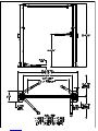
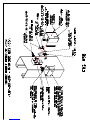
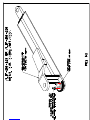
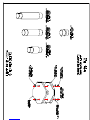
7) Before installing see FIG. #1A, #1B and #1C for lift specifications.
INSTALLATION INSTRUCTIONS
1) After unpacking lift, inspect lift for any damages due to transport and check shipping
list for any missing parts.
2) Steps #3 thru #5 are pre-assembly before standing and installing lift.
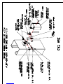
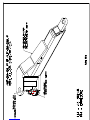
3) Assemble the overhead cross bridge assembly with the hardware and parts as shown
in FIG. #2A or FIG #2B. If one person is installing the lift then Shut Off Bar Assy.
and Switch Assy. may be installed after bolting Cross Bridge to lift.
4) Assemble the Carriage Stops ALIF-209-019-XX to the Mainside and Offside Leg
ALIF-210-090L/R using (4) 3/4-16UNC x 1 ½ bolts and (4) 3/4-16UNC nylon
locknut as shown in FIG. #5A & #5B. **IMPORTANT: NYLON LOCKNUTS
MUST BE ON THE OUTSIDE OF LIFT. IF NYLON LOCKNUTS ARE
ASSEMBLED TO THE INSIDE OF LIFT THEY WILL INTERFERE WITH
CARRIAGE.
5) Locate the (2) 3/8” x 30’-4 1/2” equalizing cables. While the legs are laying
horizontal install one end of the 3/8” cables in the carriage. Slide the carriage about
36” from the bottom of the leg up towards the top and thread the cable to the
appropriate gusset. (The three gussets with holes inside each carriage are adjustment
for the cable depending on the width of the lift. For the maximum width of lift use
lower gussets on carriages). Turn the nylon lock nut half way down the threaded stud

8
8
of the cable and pull the slack. Run the other end of the cable down and under pulley
located at the base of the leg. Repeat the same procedure for the other leg assembly.
6) Layout lift location using FIG. #1B. Maximum width of lift is 11’-6 ½” and minimum
is 10’-6 ½”. Lift moves in at 6” increments.
7) Leg assemblies should be mounted on a CONCRETE FLOOR ONLY with a
minimum thickness of 4 inches and a maximum slope not to exceed 1/16” per foot.
8) Stand leg assemblies up and position as shown in FIG. #1B.
9) Make sure the 9’-7” inside measurement leg to leg is maintained. DO NOT
ANCHOR AT THIS TIME. Depending on customers preference, lift may be moved
in 6” increments to 8’-7” inside measurement.
10)NOTE: One leg has a power unit bracket. This is the leg (Mainside) that the pumping
unit will mount to and the electrical service will be wired to. FACTORY
RECOMMENDED LOCATION IS TO THE REAR PASSENGER SIDE OF
VEHICLE.
11)Check leg (with pump mount bracket) for plumpness using a good spirit level in both
directions. Use shims (1/16” x 1 x 2 ½” and ¼” x 1” x 2 ½”) provided as necessary
for proper leveling. (Do not exceed ½” total shim height). DO NOT ANCHOR
NON-POWER COLUMN AT THIS TIME.
12)Drill and set ¾” anchor bolts. (Ref. Anchoring Tips) Use washers when final
tightening is done. Make sure all bolts are properly set and meet 125 ft. lbs of torque.
DO NOT USE AN IMPACT.
13)Check inside measurements between both columns at top and bottom to insure they
are parallel.
14)Lift Cross Bridge Assembly as shown in FIG. #2A or #2B to the top of the leg
assemblies with Switch Box assembly on the side of the power unit. Secure assembly
as shown in FIG.#3 using the (4) 7/16-14UNC x 1 1/2” bolts, (8) 7/16 flat washers,
(4) lock washers and (4) 7/16-14UNC hex nuts. Bolts heads are to be placed on the
outside with the nuts on the inside.
15)Next assemble and install the Single Point Release Pulley Bracket as shown in FIG.#3
with the LH/RH Single Point Rel. Weldm’t., (4) ¼ flat washer, (2) Pulley Sheave, (2)
1/16” Cotter Pin, (2) 7/16-14UNC x 1 1/2” bolts, (4) 7/16 flat washers, (2) lock
washers and (2) 7/16-14UNC hex nuts.
16)Attach the power unit to the main side leg using the (4) 5/16-18UNC x 1” bolts, (8)
5/16-18UNC hex nuts, and (4) 5/16 lock washers.
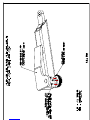
17)Next locate lock release handle, 7/8” retainer rings, 1/16” wire rope (25’-0”), 1/16”
wire rope clip and (1) 1/16” oval sleeves. Switch out shipping pin with handle on
safety latch bracket, which is located on the back of the main side leg. Secure in place

9
9
with 7/8” retainer ring see FIG. #5D. Install 1/16” wire rope on the offside legs single
point release by looping wire rope through one of the holes in the 3/8” clevis pin,
which ever holes lines up best and securing it with oval sleeve see FIG. #4. Crimp
oval sleeve. Run wire rope to other side, connect it to lock release handle (hole
farthest away from the leg) and clamp using 1/16” wire rope clip see FIG. #4. Wire
rope should not have any slack but locks on both legs should also touch leg backsides
in their normal position. If cable is loose, adjust wire rope using wire rope clip.
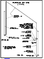
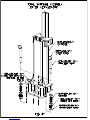
18)Locate and install the 53”, 348” (396”) and 13 1/2” hydraulic hoses see FIG. #6.
Manually raise both carriage assembly about 18” for hose installation. The 53”
hydraulic hose connect the 90 deg. adapter at the bottom of the mainside leg to the
bulk head tee. Next attach the Hose Bracket (ALIF-209-275-XX) with the Grommet
(2772-BLK) to the MS & OS Leg assemblies as shown in Fig. #3. Now thread hose
through pipe loops in leg assembly. The 348” hydraulic hose connects the 90 deg.
adapters at the bottom offside leg to the bulk head tee on the mainside leg. Thread the
hydraulic hose through pipe loops of offside leg, hose brackets, cross bridge and
mainside leg. Leave the hose bracket loose and adjust the bracket to take up the slack
of the hydraulic hose. Use 3/8 JIC nut to secure bulk head tee to main side leg. The 13
1/2” hydraulic hose connects the straight adapter of the power unit to the bulk head
tee. Do not lower carriage assemblies. Leave carriage raised to install equalizer
cables.
19)Next route the two 3/8” equalizing cables x 30’-4 ½” for WA/WS/WAS102E &
112E) as shown in FIG. #4. (The three gussets with holes inside each carriage are
adjustment for the cable depending on the width of the lift. For the maximum width
of lift use lower gussets on carriages.) Run the cable down and under pulley located at
the base of the leg. Next run cable back up through the carriage to the top of leg over
the pulley (at the top of leg) and across to the other leg, over pulley and down through
the bracket located at the top left side of carriage see FIG. #4. Secure in place with
nylon lock nut.
20)Repeat step 19 for installing cable on the other leg.
21)Adjust nuts evenly until cables are tight.
22)Next installing swing arm, rotate & slide swing arms to the center of lift to see if lift
pads are at the same height. If pads are not at the same height then shim lift forward,
backward or sideways to level lift pads. Leg of lift may become out of plumb. If lift
pads are more than 1” from being level call manufacture for further instructions.
23)Fill pumping unit with hydraulic medium oil SAE-10 or equivalent. It will take
approximately 3 US gallons. Automatic transmission fluid may be substituted.
24)Use plastic ties to secure slack in hydraulic hose and electrical cable. Slack of the
hydraulic hose is where the cross bridge and legs are connected.
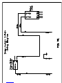
25)Power requirements: 230 Volt, single-phase power, 12-amp. Use separate circuit for
each unit and protect each circuit with 30-amp time delay fuse or circuit breaker.

10
10
Install electricity to lift coming from snap action switch to power unit. Use FIG. #11
for wiring diagram.
26)Before operating lift visually inspect lift to make sure the cable and hoses are not
rubbing or in the way of hardware or lift parts. Especially in cross bridge or legs.
27)Next purge air from hydraulic lines. Raise lift until carriages rise off of safety locks.
Crack bleeder plug located at the top of cylinder. Listen for air to escape and tighten
when hydraulic fluid starts coming out. Now raise lift to the top and lower. Repeat
cycle until no air is in the hydraulic system..
28)The above procedure may have to be repeated several times to ensure all the air has
been bled from the system.
29)Refill tank with hydraulic oil.
30)Raise lift and make sure that safety locks are synchronized as lift goes up. If locks are
not synchronized then tighten the cable on the side that is lagging.
POST INSTALLATION CHECK-OUT PROCEDURE
Posts properly shimmed and secure
Anchor bolts tightened
Pivot/sheave pins properly attached
Carriage stop bolts torqued to 2-3 ft-lbs
Electric power supply confirmed
Cables adjusted properly
Safety locks functioning properly
Confirm no hydraulic leaks
Confirm correct oil level
Lubricate all critical components
Check for overhead obstructions
Lift arms level
Confirm all screws, bolts, and pins are secure
Surrounding area is clean
Confirm operation, maintenance and safety manuals are on site.

11
11
INSPECTION AND MONTHLY MAINTENANCE
1) Inspect the cable, (6) cable pulleys and shaft for wear. Lifting cables should be
replaced every three - five years or when visible signs of damage are present. If cable
can’t be adjusted, then the cable has stretched more than 4”. DO NOT USE LIFT WITH
DEFECTIVE/WORN CABLES. Contact qualified lift service personnel.
2) Grease bearing surfaces in leg assembly minimum every 30 days or as required
depending use of lift.
3) Check equalizer cables regularly for proper tension and adjustment. Locks must be
synchronizes as lift goes up.
4) Inspect adapters and pads for damage or wear. Replace if necessary.
5) Grease swivel arm pins to insure ease of operation.
6) Inspect all hydraulic cylinders, lines and fittings for leaks and tighten if necessary.
7) Check locking latches and releases for proper operation.
8) Check arm lock device for proper operation.
9) Check hydraulic fluid level in power unit.
10) Torque anchor bolts to 125 ft. lbs.
11) Replace worn, damaged or broken parts with approved manufacture’s parts. Parts
shall be replaced by qualified lift service personnel.
12) The maximum operating hydraulic pressure developed upon lifting the rating
capacity is 2800 PSI.
13) Reference ANSI/ALI ALOIM –Safety Requirements For Operation, Inspection and
Maintenance and the Automotive Lift Safety Tips.
14) Reference ANSI/ALI ALIS - Safety Requirements for Installation and Service of
Automotive Lifts.

12
12
OPERATION INSTRUCTIONS
Reference ANSI/ALI ALOIM –Safety Requirements For Operation, Inspection
and Maintenance and the Automotive Lift Safety Tips. Vehicles Lift Points for
Frame Engaging Lifts.
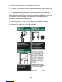
NEVER LIFT ANY VEHICLE IN ANY MANNER WITH LESS
THAN ALL FOUR (4) LIFT ARMS. RATED CAPACITY OF
EACH LIFT ARM IS NO GREATER THAN ONE FOURTH
(1/4) OF THE OVERALL LIFT CAPACITY.
RAISING THE LIFT
Read operating and safety manuals before using lift.
Always lift a vehicle according to the manufacturer's recommended
lifting points.
Position vehicle between posts.
Adjust swing arms so that the vehicle is positioned with the center of
gravity midway between pads.
NEVER use lift pad assemblies without rubber slip over pads in
place.
Use truck adapters as needed. Never exceed 9" of pad height.
Raise the vehicle by depressing button until the vehicle just lifts off
the ground. Re-check to make sure the vehicle is secure and all
locking pins are locked in place.
Raise the vehicle to desired height. Lower vehicle to nearest safety.
Always ensure safeties are engaged before any attempt is made to
work on or near vehicle.
LOWERING THE LIFT
First raise the lift in order to disengage the safeties.
Release safeties by pushing on the safety handle.
Be sure tool trays, stands and personnel are cleared from under the
vehicle.
Lower vehicle by activating lowering handle on power unit.
Before removing vehicle from lift; position lift arms and supports to
provide an unobstructed exit.
NEVER drive over lift arms.

13
13
OWNER/EMPLOYER RESPONSIBILITIES
SAVE THESE INSTRUCTIONS and deliver them to the
owner/operator/employee along with all other materials sent with this lift.
Demonstrate the operation of the lift to the owner/operator and review
correct and safe lifting procedures referencing ALI/SM-Lifting It Right.
The Owner/Employer:
Shall ensure that lift operators are qualified and that they are trained in the safe
use and operation of the lift using the manufacturer's operating instructions:
ALI/SM01-1, ALI Lifting it Right safety manual; ALI/ST-90 ALI Safety Tips
card; ANSI/ALI ALOIM-2000, American National Standard for Automotive
Lifts-Safety Requirements for Operation, Inspection and Maintenance; ALI/WL
Series, ALI Uniform Warning Label Decals/Placards; and in the case of frame
engaging lifts, ALI/LP-GUIDE, Vehicle Lifting Points/Quick Reference Guide
for Frame Engaging Lifts.
Shall establish procedures to periodically inspect the lift in accordance with the
lift manufacturer's instructions or ANSI/ALI ALOIM-2000, American National
Standard for Automotive Lifts-Safety Requirements for Operation, Inspection and
Maintenance; and The Employer shall ensure that lift inspectors are qualified and
that they are adequately trained in the inspection of the lift.
Shall establish procedures to periodically maintain the lift in accordance with the
lift manufacturer's instructions or ANSI/ALI ALOIM-2000, American National
Standard for Automotive Lifts-Safety Requirements for Operation, Inspection and
Maintenance; and The Employer shall ensure that lift maintenance personnel are
qualified and that they are adequately trained in the maintenance of the lift.
Shall maintain the periodic inspection and maintenance records recommended by
the manufacturer or ANSI/ALI ALOIM-2000, American National Standard for
Automotive Lifts-Safety Requirements for Operation, Inspection, and
Maintenance.
Shall display the lift manufacturer's operating instructions; ALI/SM 93-1, ALI
Lifting It Right safety manual; ALI/ST-90 ALI Safety Tips card; ANSI/ALI
ALOIM-2000, American National Standard for Automotive Lifts-Safety
Requirements for Operation, Inspection and Maintenance; and in the case of
frame engaging lifts, ALI/LP-GUIDE, Vehicle Lifting Points/Quick Reference
Guide for Frame Engaging Lifts; in a conspicuous location in the lift area
convenient to the operator.

14
14
Shall not modify the lift in any manner without the prior written consent of the
manufacturer.
Shall provide necessary lockout/tagout means for energy sources per ANSI
Z244.1-1982 (R1993), Safety Requirements for the Lockout/Tagout of Energy
Sources, before beginning any lift repairs.
LIFT OPERATION SAFETY
1) Do not raise a vehicle on the lift until the installation is completed as described in this
manual.
2) Operators should be trained to use and care for the lift by familiarizing themselves
with the publications listed above. The lift should never be operated by an untrained
person.• “INSTALLATION AND OWNERS MANUAL”
• “ALI/SM - LIFTING IT RIGHT”
• “ALI/ST - SAFETY TIPS”
• “ALI/LP - VEHICLE LIFTING POINTS FOR FRAME ENGAGING LIFTS”
• “ANSI/ALI ALOIM - SAFETY REQUIREMENTS FOR OPERATION,
INSPECTION, AND MAINTENANCE”
3) Always position the arms and adapters properly out of the way before pulling the
vehicle into or out of the bay. Failure to do so could damage the vehicle and/or the lift.
4) Do not overload the lift.
5) Positioning the vehicle is very important. Only trained operators should position the
vehicle on the lift. Never allow anyone to stand in the path of the vehicle as it is being
positioned.
6) Position the arms to the vehicle manufacturer’s recommended pickup points. Raise the
lift until contact is made with the vehicle. Make sure that the arms have properly engaged
the vehicle before raising the lift to a working height.
7) Keep everyone clear of the lift when the lift is moving, the locking mechanism is
disengaged, or the vehicle is in danger of falling.
8) Inspect the lift daily. The lift should never be operated if it has damaged components
or is malfunctioning. Only qualified technicians should service the lift. Replace damaged
components with manufacturer’s parts or equivalent.
9) Keep the area around the lift clear of obstacles.
10) Never override the self returning lift controls.
11) Use safety stands when removing or installing heavy vehicle components.

15
15
12) Avoid excessive rocking of the vehicle when it is on the lift.
13) To reduce the risk of personal injury, keep hair, loose clothing, fingers, and all body
parts away from moving parts.
14) The troubleshooting and maintenance procedures described in this manual can be
done by the lift’s owner/employer. Any other procedure should only be performed by
trained lift service personnel. These restricted procedures include, but are not limited to,
the following: cylinder replacement, carriage and safety latch replacement, leg
replacement, overhead structure replacement.
15) Anyone will be in the vicinity of the lift when it is in use should familiarize
themselves with the following: Caution, Warning and Safety related decals supplied with
the lift and replace them if they are illegible or missing.


17
17
TROUBLE SHOOTING GUIDE
POSSIBLE PROBLEM POSSIBLE CAUSE & SOLUTIONS
1. MOTOR DOES NOT RUN A) Breaker tripped or fuse blown
B) Check micro-switch on shut off
bar.
C) Check thermal overload in starter.
D) Defective control switch, replace
E) Faulty wiring connections. Call
electrician.
2. MOTOR RUNS BUT THE LIFT A) A foreign object under check
WILL NOT RAISE OR HOLD A LOAD valve. Push handle down and push
“raise” switch. Foreign matter
should release under pressure.
B) Remove check valve. Clean and
replace.
C) Oil level low: check oil
reservoir. With carriage in the down
position, pump reservoir should be
full.
3. MOTOR RUNS BUT THE LIFT PICKS A) Relief valve setting is too low.
UP PARTIAL LOAD ONLY. Remove back hexcap on pump and
and adjust valve clockwise.
B) Hydraulic seals damaged (call
factory for instructions)
C) Check voltage must have a
minimum of 208 volts.
4. OIL BLOWS OUT BREATHER A) Oil reservoir overfilled
B) Lift lowered too quickly while
under heavy load.
5. LIFT MAKES A GROANING A) Bleed cylinder manually.
SOUNDING WHEN RAISING OR B) Add an ounce of oil to the
LOWERING. air side of the piston.
6. LIFT RAISES UNEVENLY A) Cables are not properly adjusted
or tightened.
B) Use lighter weight oil in the
pump.

18
18
7. LIFT LOWERS SLOWLY OR A) Cylinders binding
NOT AT ALL -Contact WHIP Industries
customer support
B) Release Valve Clogged -
- Clean release valve with solvent
and blow out with air.
- Check oil - Use clean 10-WT
hydraulic oil or Dexron-III
automatic transmission fluid
only. If ATF is contaminated,
replace with clean ATF and
clean entire system.
- Replace with new part.
- Return for repair.
C) Pressure fitting too long
- Replace fitting with short
thread lead.

19
19
PARTS LIST FOR MODELS:
WA102E, WS102E, WAS102E, WA102E-24, WS102E-
24, WAS102E-24, WA112E, WS112E, WAS112E
WA112E-24, WS112E-24 & WAS112E-24
PART NUMBER DESCRIPTION QTY.
ALIF-210-284 Main side Leg Final Assy. 1
2502-06-04 #6MJIC X #4FP Adapter Fitting 1
4550K137 1/4 x 4 Nipple Sch 80 1
5315 7/16” Dia. x 1 ¼” Ext. Spring 1
5933 1/2 “ Dia. x 2 1/8” Ext. Spring 1
7130K55 11 x .18 Nylon Cable Ties 1
90126A037 7/8” SAE Flat Washer 2
91102A029 ¼” Lock Washer 1
91309A537 ¼-20UNC x ½ Hex Head Bolt 1
92865A716 ½-13UNC x 1 ½ Hex Head Bolt Grd5 2
98330A185 5/16” Dia. x 3” Adj. Clevis Pin 1
98330A245 3/8” Dia. x 2 ½” Adj. Clevis Pin 1
98338A140 3/32” x 1 Cotter Pin 3
98410A128 ¾ Ext. Retainer Ring 1
98410A131 7/8” Ext. Retainer Ring 2
AA2015010 2” Bore x 69” Stroke Hyd. Cyl. 1
ALIF-210-049 Carriage Assy. 1
90177A225 2 ¼ Dia Split Ring 2
98555A213-1.0 1 Dia. C-Retainer Ring 6
ALIF-210-050-XX Carriage Weldm’t. 1
ALIF-210-057 1 Dia. Arm Lock Pin 2
ALIF-209-107 Upper Arm Lock 2
ALIF-210-158 1 ¼ x 1/8 Comp. Spring x 7 ¼ 2
ALIF-210-088 4” Pulley Assy. 1
ALIF-209-089 Lower Pulley Pin 1
ALIF-209-090R-XX Main side Leg Weldm’t. 1
ALIF-209-125-XX Safety Latch (Mat’l. A514) 1
ALIF-209-126-XX Single Point Release Cover 1
ALIF-209-162 7 ¾ Lg. Rubber Edging 2
GL-09-057 Nylon Rub Blocks 8
GL-09-079 Safety/Caution/ Warning Decals 1 Set
GL-09-143 Lift Capacity Sticker 1
GL-09-144 Lift Instruction Sticker 1

20
20
ALIF-210-285 Offside Leg Final Assy. 1
2502-06-04 #6MJIC X #4FP Adapter Fitting 1
4550K137 1/4 x 4 Nipple Sch 80 1
5933 1/2 “ Dia. x 2 1/8” Ext. Spring 1
7130K55 11 x .18 Nylon Cable Ties 1
8901T11 ¾” Delrin Sheave 1
90126A037 7/8” SAE Flat Washer 2
91090A111 5/16” x 1 ¼ Fender Washer 2
91102A029 ¼” Lock Washer 1
91145A180 5/16” x ¼ Nylon Spacer 1
91259A580 5/16” x 5/8 Shoulder Screw 1
91309A537 ¼-20UNC x ½ Hex Head Bolt 1
92865A716 ½-13UNC x 1 ½ Hex Head Bolt Grd5 2
98330A185 5/16” Dia. x 3” Adj. Clevis Pin 1
98330A245 3/8” Dia. x 2 ½” Adj. Clevis Pin 1
98338A140 3/32” x 1 Cotter Pin 3
98410A128 ¾ Ext. Retainer Ring 1
98410A131 7/8” Ext. Retainer Ring 2
AA2015010 2” Bore x 69” Stroke Hyd. Cyl. 1
ALIF-209-049 Carriage Assy. 1
90177A225 2 ¼ Dia Split Ring 2
98555A213-1.0 1 Dia. C-Retainer Ring 4
ALIF-210-050-XX Carriage Weldm’t. 1
ALIF-210-057 1 Dia. Arm Lock Pin 2
ALIF-209-107 Upper Arm Lock 2
ALIF-210-158 1 ¼ x 1/8 Comp. Spring x 7 ¼ 2
ALIF-210-088 4” Pulley Assy. 1
ALIF-209-089 Lower Pulley Pin 1
ALIF-209-090L-XX Main side Leg Weldm’t. 1
ALIF-209-125-XX Safety Latch (Mat’l. A514) 1
ALIF-209-127-XX Single Point Release Cover 1
ALIF-209-134 O.S. Safety Latch Pin 1
ALIF-209-162 7 ¾ Lg. Rubber Edging 2
GL-09-057 Nylon Rub Blocks 8
ALIF-210-168 Two-Piece Cross Bridge Assy. 1
90126A036 ¾ SAE Flat Washer 6
98410A128 ¾ Ext. Retainer Ring 2
ALIF-209-016-XX ¾ Spacer 2
ALIF-210-088 4” Pulley Assy. 2
ALIF-209-159 Upper Pin 1
ALIF-209-159A Upper Pin 1
ALIF-209-177 Inner Cross Bridge Weldm’t. 1
ALIF-209-178 Outer Cross Bridge Weldm’t. 1
Page is loading ...
Page is loading ...
Page is loading ...
Page is loading ...
Page is loading ...
Page is loading ...
Page is loading ...
Page is loading ...
Page is loading ...
Page is loading ...
Page is loading ...
Page is loading ...
Page is loading ...
Page is loading ...
Page is loading ...
Page is loading ...
Page is loading ...
Page is loading ...
Page is loading ...
Page is loading ...
Page is loading ...
Page is loading ...
-
 1
1
-
 2
2
-
 3
3
-
 4
4
-
 5
5
-
 6
6
-
 7
7
-
 8
8
-
 9
9
-
 10
10
-
 11
11
-
 12
12
-
 13
13
-
 14
14
-
 15
15
-
 16
16
-
 17
17
-
 18
18
-
 19
19
-
 20
20
-
 21
21
-
 22
22
-
 23
23
-
 24
24
-
 25
25
-
 26
26
-
 27
27
-
 28
28
-
 29
29
-
 30
30
-
 31
31
-
 32
32
-
 33
33
-
 34
34
-
 35
35
-
 36
36
-
 37
37
-
 38
38
-
 39
39
-
 40
40
-
 41
41
-
 42
42


WHIP INDUSTRIES WA112E-12 Installation, Operation & Maintenance Manual
- Type
- Installation, Operation & Maintenance Manual
Ask a question and I''ll find the answer in the document
Finding information in a document is now easier with AI
Other documents
-
Ideal Distributors 10000 lb - iDEAL Two Post Clear Floor Lift - ALI Certified TP10KAC-DX Installation guide
-
-
Dannmar 1375647 Owner's manual
-
 TCE T9000-4S User manual
-
BendPak XPR-12CL Owner's manual
-
TUXEDO Two Post Surface Mounted Lifts TLT210-A/TLT210-AS/TLT210-XT/TLT211-AS User manual
-
-
-
-
Challenger Lifts E10 Installation, Operation & Maintenance Manual
