
Rev. A 921422-18
1
5252 East 36th Street North
Wichita, KS USA 67220-3205
TEL: 316-686-7361
FAX: 316-686-6746
TABLE OF CONTENTS
General Information ..........................................................2
Safety Instructions ............................................................2
Installation ........................................................................2
Operation ..........................................................................4
Maintenance .....................................................................4
Repair ...............................................................................4
Troubleshooting ................................................................8
Specifications ...................................................................9
Illustrated Parts List ........................................................10
Parts and Service ...........................................................11
Great Plains Industries, Inc. is a member of
the Petroleum Equipment Institute.
SAVE THESE INSTRUCTIONS
05/09
To the owner...
Congratulations on receiving your GPI fuel pump. We are
pleased to provide you with a system designed to give you
maximum reliability and efficiency.
Your fuel pump is designed, tested, and approved for use
with gasoline blends, diesel fuel blends and kerosene.
Please take all due precautions when handling these flam-
mable liquids. Your safety is important to us.
Also, to assure the longest possible service life, it is impor-
tant that you follow the operation and maintenance proce-
dures outlined in this manual. We are proud to provide you
with a quality product and dedicated support. Together
with your conscientious use, we are sure that you will obtain
years of safe, dependable service.
President
Great Plains Industries, Inc.
M-150S, M-180S and M-240S Fuel Pump
Owner’s Manual
Please contact GPI before return-
ing any product. If you are missing
parts or experience problems with
your installation, our Customer
Support Department will be happy
to assist you.
GPI Customer Support
800-835-0113 or
316-686-7361

The following safety alert symbols are used
in this manual.
DANGER indicates a haz-
ardous situation which, if
not avoided, will result in
death or serious injury.
WARNING indicates a haz-
ardous situation which, if
not avoided, could result in
death or serious injury.
GENERAL INFORMATION
The purpose of this manual is to assist you in installing,
operating and maintaining your GPI pump. This manual cov-
ers 12- and 24-volt DC electric gear pump models M-150S,
M-180S and M-240S.
Models M-150S and M-180S should be connected to a 12-volt
DC power source.
Model M-240S should be connected to a 24-volt power
source only.
Do not attempt connection of any pump to a 115-volt AC or
230-volt AC power source.
CAUTION indicates a haz-
ardous situation which, if
not avoided, may result in
minor or moderate injury.
It is your responsibility to:
• know and follow applicable national, state, and local safety
codes pertaining to installing and operating electrical equip-
ment for use with flammable liquids.
• know and follow all safety precautions when handling
petroleum fuels.
• insure that all equipment operators have access to adequate
instructions concerning safe operating and maintenance
procedures.
Observe all safety precautions concerning safe handling of
petroleum fuels.
To ensure safe operation, all fuel transfer systems must be
properly grounded. Proper grounding means a continuous
metal-to-metal contact from one component to the next,
including tank, bung, pump, meter, filter, hose and nozzle.
Care should be taken to ensure proper grounding during initial
installation and after any service or repair procedures. For
your safety, please take a moment to review the warnings
below.
To prevent physical injury, observe precautions against fire or
explosion when dispensing fuel. Do not operate the system in
the presence of any source of ignition including running or hot
engines, lighted cigarettes, or gas or electric heaters.
Observe precautions against electrical shock when operating
the system. Serious or fatal shock can result from operating
electrical equipment in damp or wet locations.
Inspect external pump wiring regularly to make sure it is
correctly attached to the battery. To avoid electrical shock,
use extra care when connecting the pump to power.
Avoid prolonged skin contact with petroleum fuels. Use
protective goggles, gloves and aprons in case of splashing
or spills. Change saturated clothing and wash skin promptly
with soap and water.
Observe precautions against electrical shock when servicing
the pump. Always disconnect power before repairing or
servicing. Never apply electrical power to the system when
any of the coverplates are removed.
If using solvent to clean pump components or tank, observe
the solvent manufacturer’s recommendations for safe use
and disposal.
This pump is designed to self-prime with dry gears. Expect
suction lift as follows:
Manual Nozzle: 5.5 feet (1.7 m) with diesel
6.7 feet (2.1 m) with gasoline
Automatic Nozzle: 4.8 feet (1.5 m) with diesel
5.8 feet (1.8 m) with gasoline
2
INSTALLATION
An automatic bypass valve prevents pressure build up
when the pump is on with the nozzle closed. To avoid
damage, do not run the pump more than 10 minutes with
the nozzle closed.
The duty cycle of this pump is 30 minutes ON and 30 minutes
OFF. Allow the pump to cool for 30 minutes.
This pump is designed for use only with gasoline (up to 15%
alcohol blends such as E15), diesel fuel (up to 20% biodiesel
blends such as B20) and kerosene. Do not use this pump
for dispensing any fluids other than those for which it was
designed. To do so may damage pump components and will
void the warranty.
This pump is designed to operate on a typical DC automotive
electrical system. The pump is designed to operate with the
appropriate DC voltage at the motor leads and the ratings are
determined at this voltage. Performance may vary due to length
of power cord, battery condition or output from the vehicle
charging system that will affect system voltage.
Do not leave the system running with fluids. “Dry running” can
damage the pump.
Do not pump the tank completely dry, as contaminants from
the bottom of the tank may enter the pump.
SAFETY INSTRUCTIONS
DANGER
WARNING
CAUTION

If you require a greater initial prime height, coat the gears with
fluid by removing the plug on the top of the pump and pour
a small quantity of motor oil into the gear cavity. Replace the
plug and try again. A foot valve with pressure relief may be
needed to maintain prime.
Make sure all threaded fuel connections are wrapped with three
to four turns of thread tape or a pipe thread sealant approved
for use with petroleum fuels.
Install Bung Adapter and Suction Pipe
• Tighten the bung adapter snugly into the fuel tank.
• Place the union ring gasket into the inlet fitting on the
bottom of the pump.
• Thread the suction pipe into the inlet fitting and tighten
until snug.
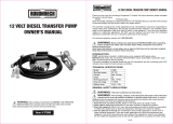
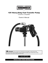
Install Pump on Tank
• Clean the tank interior of all dirt and foreign material.
• Extend the suction pipe to its full length and insert into
the tank opening. (Figure 1)
The suction pipe will
adjust to the length
needed to rest on the
tank bottom.
• Place the pump on the bung adapter and tighten the union
ring securely with a pipe wrench. Make sure the union ring
is not cross-threaded.
• To prevent pressure buildup and possible fuel leaks through
the nozzle, make sure the tank is vented. A vent cap rated
at 3 psi or less is recommended.
Install Electrical Connections
A grounding connection is provided. It is identified as a green
colored binding head screw in the electrical cavity.
Models M-150S and M-180S should be connected to a 12-volt
DC power source.
Model M-240S should be connected to a 24-volt DC power
source.
Do not attempt connection of any pump to a 115-volt AC or
230-volt AC power source.
For installation in unclassified areas, the supplied power cord,
fuse and strain relief grip may be used.
NOTE: These components have not been evaluated as part
of the UL Listed Equipment and are not intended for use
in a Hazardous (Classified) Location.
3
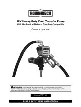
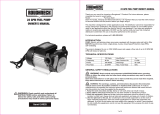
To install the power cord, remove the electrical coverplate.
(Figure 2)
If necessary, trim the power cord to the desired length. Strip
3 to 4 inches (7.5 to 10 cm) of outer insulation from the power
cord end. Then strip 1/2 inch (1.3 cm) of insulation from the
power cord wires.
Slide the strain relief grip onto the power cord so that the
threaded end of the strain relief grip faces the stripped power
wires. (Figure 3)
Insert the power cord through the 1/2 inch NPT connection on
the back of the pump. (Figure 4) Using wire nuts, connect the
black wire to the black wire and the red wire to the red in the
pump’s electrical cavity. Position the wires inside the electrical
cavity and tighten the strain relief grip securely. Make sure sur-
faces are clean. Install the coverplate and tighten securely.
Figure 3
Figure 1
Figure 2
Figure 4
Carefully route the power cord to the battery, protecting
the power cord from hot surfaces, sharp edges or any-
thing that could damage the power cord, resulting in a
short circuit.
A fuse is provided to protect the power cord and motor.
Install fuse in the red wire of the power cord as close as
possible to the battery. Connect the red wire of the fuse to
the positive (ungrounded) side of battery. Connect black
wire to the negative (grounded) side of the battery.
Failure to follow these instructions could result in death,
serious injury or loss of equipment due to short circuit,
fire or explosion.
WARNING

Motor Protector (Model M-240S)
An inline fuse provides motor protection on the 24-volt mod-
els. Follow the instructions in the Repair Section to replace
the fuse.
This pump is designed for minimum maintenance. Motor bear-
ings are sealed and require no lubrication. Inspect the pump
and components regularly for fuel leaks and make sure the
hose and power cord are in good condition. Keep the pump
exterior clean to help identify leaks.
Do not use this pump for water, chemicals, or herbicides.
Dispensing any fluid other than those listed in this manual will
damage the pump. Use of the pump with unauthorized fluids
will void the warranty.
To Clean or Replace Strainer
Turn the pump off and disconnect from power. Remove the
strainer coverplate. (Figure 5) Remove the inlet strainer and in-
spect for damage or clogs. Clean the strainer with a soft-bristled
brush and solvent. If the strainer is very dirty, compressed air
may be used. If damaged, replace the strainer.
Place the strainer in the cavity. Clean the coverplate and O-ring.
Coat the O-ring lightly with grease. Ensure the coverplate O-ring
is properly seated and tighten the strainer coverplate.
If the pump is to be installed in a Hazardous (Classified)
location, it must be installed by a licensed electrician and
conform to National Fire Protection Association (NFPA)
codes 30 and 70. You as the owner, are responsible for
seeing that the installation and operation of your pump
complies with NFPA codes as well as any applicable
state and local codes. Rigid conduit must be used to
install wiring. Note that the lead wires are factory-sealed
isolating the motor from the junction box.
Failure to follow these wiring instructions may result in
death or serious injury from shock, fire or explosion.
Install Hose and Nozzle
After sealing the threads, tighten the hose into the pump outlet
and the nozzle on the hose. The nozzle can be placed in the
nozzle holder only when the pump is off.
The nozzle holder allows the pump to be locked when the
nozzled is in place.
ALWAYS FOLLOW SAFETY PRECAUTIONS WHEN
OPERATING THIS EQUIPMENT. REVIEW THE SAFETY
INSTRUCTIONS. Before each use, repair leaks around seals
or connections. Make sure hoses are in good condition and
connections are tight. Make sure the work area is dry. MAKE
SURE THE PUMP IS PROPERLY GROUNDED. Repair any
corroded or damaged wiring before use. Ensure the tank
contains enough fuel. Make sure the fuel is not contaminated
with debris.
Dispense Fuel
Turn the pump on by removing the nozzle from its holder and
pushing up the switch lever. Insert the nozzle into the receiving
tank and squeeze the handle to start fuel flow. When done,
release the nozzle handle, turn the pump off, and return the
nozzle to its holder.
This pump is designed to be self-priming. If fuel is not delivered
within 15 to 20 seconds, turn the pump off and refer to the
priming information in the Troubleshooting Section.
An automatic bypass valve prevents pressure buildup when
the pump is on with the nozzle closed. To avoid pump dam-
age, do not run the pump for more than 10 minutes with the
nozzle closed.
Motor Protector (Models M-150S and M-180S only)
The pump contains a motor protector that provides added
protection against motor damage. It must be reset manually.
If the motor protector trips, reset by turning the switch OFF. Let
the pump cool then turn ON again. If the motor protector trips
again, see the Troubleshooting Section of this manual.
4
OPERATION
MAINTENANCE
REPAIR
Figure 5
DANGER
Carefully inspect all parts for wear or damage. Replace compo-
nents, as necessary. The Illustrated Parts List gives information
on replacement parts and kits.
Review the Safety Instructions before proceeding.
Observe precautions against electrical shock when servic-
ing the pump. Always disconnect power before repairing
or servicing. Never apply electrical power to the system
when any of the coverplates are removed.
WARNING

5
Avoid prolonged skin contact with petroleum fuels. Use
protective goggles, gloves and aprons in case of splash-
ing or spills. Change saturated clothing and wash skin
promptly with soap and water.
Remove Pump from Tank
• Turn the pump OFF and disconnect from power.
• Turn the union ring counterclockwise to release the inlet
fitting.
• Lift the pump and suction pipe straight up from the bung
adapter.
• Elevate the nozzle and hose to allow excess fuel to drain
into the tank.
• Wipe the entire system with a clean cloth.
Service O-Rings
A Wet Seal Kit contains all seals for your pump and should
be on hand when performing repairs. Old seals may then be
replaced with new seals.
In general, when inspecting O-rings, look for breaks, wear, and
signs of deterioration, such as swelling. Replace, as necessary.
Before seating, coat O-rings with light grease.
Replace Gears and Drive Key
• Turn the pump OFF and disconnect from power.
• Remove the gear coverplate. (Figure 6)
• Lift the drive key and gears from the pump. (Figure 7)
• Inspect the gears and key for wear and damage. Replace,
as necessary.
• Wipe the gear cavity with a clean cloth.
• Replace the gears. Make sure they turn freely.
• Replace the drive key.
• Make sure the gear coverplate O-ring is securely in place.
Tighten the coverplate to the housing.
Clean or Replace Bypass Poppet
• Turn the pump OFF and disconnect from power.
• Using a drive ratchet or extension, remove the pipe plug
from the top outlet port. (Figure 8)
• Remove the gear coverplate and O-ring from the pump
housing.
• Lift the drive key and two gears from the pump.
• To clean the bypass poppet:
a. With a clean cloth, wipe the poppet cavity through the
top outlet port.
b. Push down on the poppet until the poppet O-ring is
exposed inside the housing. (Figure 9)
c. Using a clean cloth, rotate the poppet and clean it
thoroughly.
• To remove or replace the bypass poppet:
a. As above, push down on the poppet until the O-ring
is exposed.
b. Remove the O-ring with a small screwdriver or similar
tool. Take care not to damage the poppet or O-ring.
(Figure 10)
Figure 6
Figure 7
Figure 8
Figure 9
▲
WARNING

c. From inside the housing, use a small screwdriver to
push the poppet and spring through the top outlet
port. (Figure 11)
d. Wipe the poppet and gear cavities with a clean cloth.
e. Replace the poppet, O-ring, and spring, as necessary.
NOTE: Replace O-ring if damaged, swollen, or loose-fitting.
• To assemble, place the spring and poppet into the poppet
cavity through the top outlet port. Compress the poppet
into the housing until the poppet appears in the lower
chamber. (see Figure 10) Coat the O-ring lightly with grease
and slip over the poppet head. Make sure the O-ring is
well-seated.
• Push on the poppet through the top outlet port to make
sure it moves freely.
• Install the pipe plug again.
• Replace the gears and drive key. Make sure gears turn
freely with the key removed.
• Make sure the gear coverplate O-ring is in place. Tighten
the coverplate to the pump housing.
Replace Power Switch
• Turn the pump OFF and disconnect from power.
• Remove the switch coverplate from the pump housing.
(Figure 12)
• Remove the torx head screw, then remove the switch
assembly. (Figure 13)
• Models M-150S and M-180S: Remove one pump wire
from the back of the switch and one wire from the circuit
protector.
• Model M-240S only: Remove both pump wires from the
back of the switch.
• Install a new switch by reversing the above procedure.
Insert the switch assembly into the pump cavity. Place
the red wire between the circuit breaker and the wall of
the pump. Make sure the O-ring is seated properly before
tightening the switch coverplate.
NOTE: For the proper operation of the switch lever and cam,
attach the mounting plate to the switch with a clearance
of 0.175 or about 3/16 inch. (Figure 14)
Replace Motor Protector
NOTE: The pump can remain on the tank during motor protec-
tor replacement.
• Turn off the pump and disconnect from power.
• Remove the switch coverplate from the pump housing.
(Figure 15)
6
Figure 10
O-ring Groove
➤
Poppet O-ring
➤
Spring
➤
Figure 11
Figure 12
Figure 13
Figure 14
Figure 15

7
• Remove switch bracket mounting screw and gently pull
switch from switch cavity. (Figure 16)
NOTE: Switch shown is for models M-150S and M-180S.
Model M-240S switch does not require a jumper wire
and circuit breaker.
• Remove the red wires from the terminals on the back of
the switch.
• Remove the remaining wire on motor protector then remove
the motor protector from switch cavity.
• Install new motor protector by reversing above proce-
dure.
NOTE: Make sure the O-ring is seated properly before tighten-
ing the switch coverplate.
Replace Switch Lever or
Switch Lever Shaft O-Ring
• Turn off the pump and disconnect from power.
• Remove the switch coverplate from the pump housing.
• Remove the screw connecting the switch cam to the
coverplate.
• Remove the cam and switch lever.
• Replace the switch lever or switch lever shaft O-ring as
needed.
• Reassemble by reversing the above procedure. Make
sure the O-ring is seated properly before tightening the
coverplate.
Replace Motor Shaft Seal
• Turn the pump OFF and disconnect from power.
• Remove the gear coverplate, gears, and drive key as
described in Gear Replacement instructions.
• Remove the motor from the pump housing.
• Remove the motor shaft seal by prying out with a small
screwdriver. (Figure 17)
• Lubricate the gear shaft with WD-40 or a similar pene-
trating oil.
• Press a new motor shaft seal evenly in the pump housing
until seated. Lubricate the seal with a lightweight motor
oil.
• Gently slide the shaft through the seal until the motor is
flush against the pump housing.
• Tighten the motor to the pump housing. Check for proper
installation by working a .0015 feeler gauge around the
motor flange. The gauge should not fit between the flange
and the housing.
• Install the gears and drive key as described in Gear Re-
placement instructions.
Replace Motor
In order to preserve the UL Listing or CSA Certification for
pump safety, return the entire pump to the factory for motor
repair or replacement. For products serviced outside the fac-
tory, the UL and CSA nameplates must be defaced to indicate
the equipment may no longer meet the requirements for UL
Listing or CSA Certification. This does not apply to products
serviced outside the factory under the UL program for Rebuilt
Motors for Use in Hazardous Locations and the CSA rebuild
program.
Figure 16
Figure 17
Back of Pump

SYMPTOM PROBABLE CAUSE CORRECTIVE ACTION
A. MOTOR DOES NOT 1. Fuse blown Inspect fuse in fuse holder on power cord. If blown, replace.
RUN
2. Switch defective Remove switch coverplate and inspect switch. Replace, if necessary.
3. Motor burned out Replace motor as described in the Repair Section.
4. Switch or electrical connections faulty Inspect for damaged motor protector, defective wiring or switch, or improper
(Model M-150S and Model M-180S) electrical connections. Replace as needed and re-install.
5. Circuit breaker tripped Turn power off at source. Inspect the pump thoroughly; clean or repair. Reset
circuit breaker by turning the power switch off then back on.
B. MOTOR RUNS BUT 1. Suction pipe clogged, damaged, or missing Remove pump from tank. Inspect suction pipe. Clean or replace, as necessary.
2. Gear coverplate or O-ring damaged Remove and inspect the coverplate and O-ring. Replace, as necessary. Refer
to the Repair Section on Servicing O-rings.
3. Strainer clogged or defective Remove strainer coverplate. Remove and clean strainer. Install again.
4. Bypass poppet O-ring worn or missing Inspect O-ring using instructions in the Repair Section. Replace, if necessary.
5. Bypass poppet O-ring dirty Remove poppet assembly and clean poppet and cavity.
6. Bypass poppet binding or damaged Using instructions in the Repair Section, remove the bypass poppet, spring,
and O-ring. Clean cavity. Inspect and replace components, as necessary.
7. System air leak Tighten all pump fittings and connections. Inspect suction pipe for leaks or
damage.
8. System air lock This can occur if external filter, meters, or an off-the-shelf automatic nozzle is
used. To correct, remove the pipe plug in the top outlet port and fill the gear
cavity with fuel. Use of a factory-supplied automatic nozzle is recommended.
9. Poor connections or low voltage Make sure electrical connections are secure. Also check battery voltage.
10. Fuel level low Fill tank.
11. Motor running backwards due to Connect red wire to positive (+) ungrounded side of battery. Gear with key
incorrect polarity should turn counterclockwise.
C. LOW FLOWRATE 1. Poor connections or low voltage Make sure electrical connections are secure. Also check battery voltage
2. Strainer partially clogged Remove the strainer coverplate. Remove and clean the strainer. Install again.
3. Suction pipe clogged or damaged Remove pump from tank. Inspect suction pipe. Clean or replace, as necessary.
4. Fuel tank empty Fill tank.
5. Using off-the-shelf automatic nozzle Factory-supplied automatic nozzle is recommended.
6. System air leak Tighten all pump fittings and connections. Inspect suction pipe for leaks or
damage. Replace, as necessary.
7. Bypass poppet spring weak Using instructions in the Repair Section, remove the bypass poppet and
inspect spring. Replace, if necessary.
D. MOTOR STALLS 1. Motor protector activated Turn off switch. Allow motor to cool, then turn on switch.
2. Gears locked Remove gear coverplate and inspect gears and drive key. Make sure gears
turn freely with the key removed. Replace, if worn.
3. Wiring defective Use Wiring instructions in the Installation Section to ensure proper connections.
4. Bypass poppet binding or damaged Using instructions in the Repair Section, remove the bypass poppet, spring,
and O-ring. Clean cavity. Inspect components and replace, as necessary.
5. Motor defective Replace motor as described in the Repair Section.
E. SWITCH FAILS TO 1. Switch or electrical connections faulty Inspect for a blown fuse, defective wiring or switch, or improper electrical
OPERATE MOTOR (Model M-240S) connections. Replace or install again, as necessary. Refer to Switch Replace-
ment instructions in the Repair Section.
2. Motor burned out Replace motor as described in the Repair Section.
3. Motor protector activated Turn off switch. Allow motor to cool, then turn on switch.
4. Switch or electrical connections faulty Inspect for damaged motor protector, blown fuse, defective wiring or switch,
(Models M-150S and M-180S) or improper electrical connections. Replace as needed and re-install.
F. RAPID OVERHEATING 1. Duty cycle too long Pump operation should not exceed the standard duty cycle of 30 minutes ON,
OF MOTOR and 30 minutes OFF. Allow the pump to cool for 30 minutes.
2. Strainer clogged Remove strainer coverplate. Remove and clean strainer. Install again.
3. Suction pipe clogged or damaged Remove pump from tank. Inspect suction pipe. Clean or replace, as necessary.
4. Gears worn Remove gear coverplate and inspect gears and drive key. Make sure gears
turn freely with key removed. Replace, if necessary.
5. Fuel level low Fill tank.
6. Running too long in bypass mode Limit bypass operation to 10 minutes.
8
TROUBLESHOOTING
DOES NOT PUMP
WHEN OPERATING
IN BYPASS MODE

Application Designed to safely transfer low viscosity petroleum fuels such as gasoline (up to 15% alcohol
blends such as E15), diesel fuel (up to 20% biodiesel blends such as B20) and kerosene.
Pump is designed for permanent mounting on vented storage tanks.
Pump Housing Lightweight, corrosion-resistant, cast aluminum body,
convenient union ring for easy installation.
Performance:
Pump Rate Up to 15 GPM (57 LPM) Up to 18 GPM (68 LPM) Up to 15 GPM (57 LPM)
Duty Cycle 30 min. ON, 30 min. OFF 30 min. ON, 30 min. OFF 30 min. ON, 30 min. OFF
Suction Lift: Manual Nozzle Up to 5.5 feet (1.7 meters) Up to 5.5 feet (1.7 meters) Up to 5.5 feet (1.7 meters)
Automatic Nozzle Up to 4.8 feet (1.5 meters) Up to 4.8 feet (1.5 meters) Up to 4.8 feet (1.5 meters)
Operating Temperature -20°F to 125°F (-29°C to 52°C)
Operating Pressure 15 PSI
Electrical Specifications:
Input 12-volt DC 12-volt DC 24-volt DC
Current Draw 18 amps 20 amps 9 amps
Motor 1900 RPM, 1/5 hp (150 watts) 2000 RPM, 1/4 hp (187 watts) 1900 RPM, 1/5 hp (150 watts)
Motor Approval UL Listed, CSA Certified UL Listed, CSA Certified UL Listed, CSA Certified
Motor Protection 20 amp circuit breaker 25 amp circuit breaker 15 amp fuse
Cord 18 feet of 12 gauge (5.5 meters) 18 feet of 12 gauge (5.5 meters) 18 feet of 12 gauge (5.5 meters)
Fuse 25 amp 30 amp 15 amp
Mechanical Connection:
Bung 2 inch NPT 2 inch NPT 2 inch NPT
Inlet 1 inch NPT 1 inch NPT 1 inch NPT
Outlet 3/4 inch NPT 1 inch NPT 3/4 inch NPT
Accessories:
Hose Type Buna-N Electrically Buna-N Electrically Buna-N Electrically
Conductive Discharge Hose Conductive Discharge Hose Conductive Discharge Hose
Hose Size 3/4 in. x 12 ft. (3.7 m) 1 in. x 12 ft. (3.7 m) 3/4 in. x 12 ft. (3.7 m)
Manual Nozzle 3/4 inch Unleaded 1 inch Leaded 3/4 inch Unleaded
Automatic Nozzle 3/4 inch Unleaded 3/4 inch Unleaded N/A
Weight:
Manual Nozzle 23 lbs. (10.5 kg) 26.5 lbs. (12.0 kg) 23 lbs. (10.5 kg)
Automatic Nozzle 24 lbs. (10.8 kg) 27 lbs. (12.2 kg) N/A
9
SPECIFICATIONS
M-150S M-180S M-240S

10
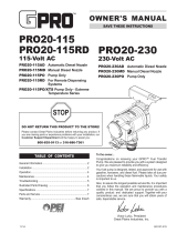
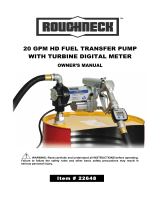
ILLUSTRATED PARTS LIST
110016-1 Inlet Fitting
110122-1 Reducer (M-180S only)
110158-1 Union Ring
110191-1 Jumper Wire
110500-01 15-amp Fuse Kit (M-240S)
110500-02 25-amp Fuse Kit (M-150S)
110500-03 30-amp Fuse Kit (M-180S)
110504-1 Fuel Pump Overhaul Kit - Includes 2 Gears, Drive Key &
O-Rings
110524-1 Armature Assembly Kit (M-150S)
110524-2 Armature Assembly Kit (M-240S)
110525-1 Brush Card Assembly Kit - Includes Brush Holder Assembly
110526-1 Motor Housing Kit - Includes Motor Housing Assembly
110527-1 Battery Clamp Kit - Includes 2 Battery Clamps
110530-01 Nozzle Spout
110906-1 Wet Seal Kit - Includes O-Rings & Motor Shaft Seal
110907-1 Gear Kit - Includes 2 Gears & Drive Key
110908-1 Poppet Seal Kit - Includes Poppet O-Ring
110909-1 Bung Adapter Kit
110910-02 Switch Kit - Includes Switch
110913-2 Spare Key Kit - Includes Spare Drive Key
110927-04 Gear Coverplate Kit (M-150S, M-240S)
110927-05 Gear Coverplate Kit (M-180S)
111501-1 Adapter Kit
115527-2 Suction Pipe Extension, 15 inch
902006-31 M-150S Motor Protector Only
902006-38 M-180S Motor Protector Only
906001-4 Pre-Vent Vapor Control Cap (3 psi)
Item No.
No. Part No. Description Req’d.
2 904002-23 Sems Screw, 1/4-20 x 3/4 in. ........................... 9
3 119000-1 Motor, 12-volt (UL) (M-150S) ........................... 1
119001-1 Motor, 12-volt (UL) (M-180S) ........................... 1
119000-2 Motor, 24-volt (UL) (M-240S) ........................... 1
4 11002502 Seal, Motor Shaft ............................................. 1
5 904002-17 Strain Relief Sealing Grip (12-volt & 24-volt) ... 1
7 904001-42 Pipe Plug, 3/4 inch ........................................... 1
8 110010-1 Bypass Poppet ................................................ 1
9 110131-2 Spring, Bypass Poppet (M-150S, M-240S) .... 1
110011-2 Spring, Bypass Poppet (M-180S) .................... 1
11 110265-02 Power Cord, 12 ga. x 18 ft. (5.5 m) .................. 1
16 110026-1 Gear Coverplate O-Ring .................................. 1
18 110024-1 Coverplate, Strainer ......................................... 1
19 110026-4 Strainer Coverplate O-Ring .............................. 1
20 110009-1 Inlet Strainer ..................................................... 1
21 110195-02 Coverplate, Electrical ...................................... 1
22 110285-01 Electrical Coverplate Gasket............................ 1
23 110277-05 M-150 Switch Assembly .................................. 1
110277-06 M-240S Switch Assembly ................................ 1
110277-07 M-180S Switch Assembly ................................ 1
29 110026-6 Switch Coverplate O-Ring ............................... 1
30 110276-01 Switch Coverplate Assembly ........................... 1
31 110032-1 Gasket, Union Ring ......................................... 1
33 110100-1 Suction Pipe Assembly .................................... 1
34 110187-1 Hose, 3/4 in. x 12 ft., (3.7 m) ............................ 1
110188-1 Hose, 1 in. x 12 ft., (3.7 m) (M-180S only)........ 1
35 110121-8 Nozzle, Automatic 3/4 in., Unleaded (UL) ........ 1
110120-1 Hook for Automatic Nozzle .............................. 1
904001-88 Set Screw for Nozzle Hook .............................. 1
36 110155-1 Nozzle, Manual 3/4 in., Unleaded .................... 1
110155-3 Nozzle, Manual 1 in., Leaded ........................... 1
38 904002-24 Sems Screw ..................................................... 4
39 904002-22 Sems Screw ..................................................... 4
40 904006-86 Tapping Screw ................................................. 2
41 110360-01 Nozzle Cover .................................................... 1
Items Not Shown
39
18
19
20 2
30
23
40
41
5
2
3
4
7
8
9
29
21
16
38
34
35
36
31
33
11
22

In order to preserve the UL Listing for the motor, do not at-
tempt to service the motor. For products serviced outside the
factory, the UL nameplate must be defaced to indicate that
the equipment may no longer meet the requirements for UL
Listing. This does not apply to products serviced outside the
factory under the UL program for Rebuilt Motors for Use in
Hazardous Locations.
For warranty consideration, parts, or other service informa-
tion, please contact your local distributor. If you need further
assistance, contact the GPI Customer Service Department in
Wichita, Kansas, during normal business hours.
A toll free number is provided for your convenience.
1-800-835-0113
To obtain prompt, efficient service, always be prepared with
the following information:
1. The model number of your pump.
2. The serial number or manufacturing date code of your
pump.
3. Part descriptions and numbers.
Part information can be obtained from the Illustrated Parts
List.
For warranty work, always be prepared with your original sales
slip or other evidence of purchase date.
Please contact GPI before returning any parts. It may be
possible to diagnose the trouble and identify needed parts
in a telephone call. GPI can also inform you of any special
requirements you will need to follow for shipping fuel dispens-
ing equipment.
Do not return the pump or parts without authority from the
Customer Service Department. Due to strict government
regulations, GPI cannot accept parts unless they have been
drained and cleaned.
PARTS AND SERVICE
11
SAVE THESE INSTRUCTIONS
CAUTION

GPI and the electric gear pump are registered trademarks of
Great Plains Industries, Inc.
© 2009 GREAT PLAINS INDUSTRIES, INC., Wichita, KS
Printed in U.S.A.
5252 East 36th Street North
Wichita, KS USA 67220-3205
TEL: 316-686-7361
FAX: 316-686-6746
Rev. A 921422-1805/09
LISTED MOTOR
Limited Warranty Policy
Great Plains Industries, Inc. 5252 E. 36
th
Street North, Wichita, KS USA 67220-3205, hereby provides a limited warranty against defects in
material and workmanship on all products manufactured by Great Plains Industries, Inc. This product includes a 2 year warranty from date
of purchase as evidenced by the original sales receipt. A 30 month warranty from product date of manufacture will apply in cases where the
original sales receipt is not available. Reference product labeling for the warranty expiration date based on 30 months from date of manufacture.
Manufacturer’s sole obligation under the foregoing warranties will be limited to either, at Manufacturer’s option, replacing or repairing defective
Goods (subject to limitations hereinafter provided) or refunding the purchase price for such Goods theretofore paid by the Buyer, and Buyer’s
exclusive remedy for breach of any such warranties will be enforcement of such obligations of Manufacturer. The warranty shall extend to the
purchaser of this product and to any person to whom such product is transferred during the warranty period.
This warranty shall not apply if:
A. the product has been altered or modified outside the warrantor’s duly appointed representative;
B. the product has been subjected to neglect, misuse, abuse or damage or has been installed or operated other than in accordance
with the manufacturer’s operating instructions.
To make a claim against this warranty, contact the GPI Customer Service Department at 316-686-7361 or 800-835-0113. Or by mail at:
Great Plains Industries, Inc.
5252 E. 36
th
St. North
Wichita, KS, USA 67220-3205
GPI will step you through a product troubleshooting process to determine appropriate corrective actions.
GREAT PLAINS INDUSTRIES, INC., EXCLUDES LIABILITY UNDER THIS WARRANTY FOR DIRECT, INDIRECT, INCIDENTAL AND CONSEQUENTIAL
DAMAGES INCURRED IN THE USE OR LOSS OF USE OF THE PRODUCT WARRANTED HEREUNDER.
The company herewith expressly disclaims any warranty of merchantability or fitness for any particular purpose other than for which it was
designed.
This warranty gives you specific rights and you may also have other rights which vary from U.S. state to U.S. state.
Note: In compliance with MAGNUSON MOSS CONSUMER WARRANTY ACT – Part 702 (governs the resale availability of the warranty terms).
-
 1
1
-
 2
2
-
 3
3
-
 4
4
-
 5
5
-
 6
6
-
 7
7
-
 8
8
-
 9
9
-
 10
10
-
 11
11
-
 12
12


GPI M-180S-AU Owner's manual
- Type
- Owner's manual
- This manual is also suitable for
Ask a question and I''ll find the answer in the document
Finding information in a document is now easier with AI
Related papers
-
GPI G20-012MD Owner's manual
-
GPI HP-100-NUL User manual
-
GPI EZ-8 Owner's manual
-
-
-
-
GPI 01N31GM User manual
-
-
-
Other documents
-
 Better Built Steel Transfer Fuel Tank Owner's manual
-
 Better Built Steel Transfer Fuel Tank Owner's manual
-
 ROUGHNECK 12V Fuel Transfer Pump Owner's manual
-
 ROUGHNECK Heavy-Duty Fuel Transfer Pump Owner's manual
-
 GPro 115V AC Commercial Grade Fuel Transfer Pump Owner's manual
-
 ROUGHNECK 41874 Portable Fuel Transfer Box Kit Owner's manual
-
 ROUGHNECK Heavy-Duty Fuel Transfer Pump Owner's manual
-
 ROUGHNECK 120V Fuel Transfer Pump Owner's manual
-
 ROUGHNECK 12V Fuel Transfer Pump Owner's manual
-
Eaton 70160 User manual


