Page is loading ...

MURELLE HE
Installation and
servicing instructions
GB


3
Please refer to commissioning instructions for filling in the log book
Note: All CORGI registered installers carry a CORGI ID Card.
You can check your installer is CORGI Registered by calling 01256 372300
CONTENTS
1 DESCRIPTION OF THE BOILER . . . . . . . . . . . . . . . . . . . . . . . . . . . . . . . . . . . . . . . . . . . . . . . . . . . . . . . . . . . . . . . . . . . . . . . . pag. 4
2 INSTALLATION . . . . . . . . . . . . . . . . . . . . . . . . . . . . . . . . . . . . . . . . . . . . . . . . . . . . . . . . . . . . . . . . . . . . . . . . . . . . . . . . . . . . . . . pag. 9
3 CHARACTERISTICS . . . . . . . . . . . . . . . . . . . . . . . . . . . . . . . . . . . . . . . . . . . . . . . . . . . . . . . . . . . . . . . . . . . . . . . . . . . . . . . . . . . pag. 20
4 USE AND MAINTENANCE (including BENCHMARK) . . . . . . . . . . . . . . . . . . . . . . . . . . . . . . . . . . . . . . . . . . . . . . . . . . . . pag. 25
5 FAULT FINDING . . . . . . . . . . . . . . . . . . . . . . . . . . . . . . . . . . . . . . . . . . . . . . . . . . . . . . . . . . . . . . . . . . . . . . . . . . . . . . . . . . . . . . pag. 33
6 REPLACEMENT OF PARTS . . . . . . . . . . . . . . . . . . . . . . . . . . . . . . . . . . . . . . . . . . . . . . . . . . . . . . . . . . . . . . . . . . . . . . . . . . . . pag. 34
7 EXPLODED VIEWS . . . . . . . . . . . . . . . . . . . . . . . . . . . . . . . . . . . . . . . . . . . . . . . . . . . . . . . . . . . . . . . . . . . . . . . . . . . . . . . . . . . pag. 36
SIME COMBINATION BOILERS
Installer checklist
Please remember to carry out the following checks after installation. This will achieve complete customer satis-
faction, and avoid unnecessary service calls. A charge will be made for a service visit where the fault is not due to
a manufacturing defect.
– Has a correct by-pass been fitted and adjusted?
– Has the system and boiler been flushed?
– Is the system and boiler full of water, and the correct pressure showing on the pressure gauge?
– Is the Auto Air Vent open?
– Has the pump been rotated manually?
– Is the gas supply working pressure correct?
– Is the boiler wired correctly? (See installation manual).
– Has the D.H.W. flow rate been set to the customer requirements?
– Has the customer been fully advised on the correct use of the boiler, system and controls?
– Has the log book provided been completed?
– Has the Aqua Guard Filter been cleaned (see 4.5.2)?
IPX4D
Murelle System HE 12: Gas Council number 41-283-05 Murelle HE 25: Gas Council number 47-283-10
Murelle System HE 20: Gas Council number 41-283-06 Murelle HE 30: Gas Council number 47-283-11
Murelle System HE 25: Gas Council number 41-283-07 Murelle HE 35: Gas Council number 47-283-12
Murelle System HE 30: Gas Council number 41-283-08
Murelle System HE 35: Gas Council number 41-283-09
These appliances comply with the S.E.D.B.U.K. scheme, band “A”

4
1.1 INTRODUCTION
MURELLE HE - MURELLE SYSTEM HE are
premixed gas condensation thermal modu-
les that employ a microprocessor-based
technology to control and manage all the
functions. All modules are compliant with
European Directives 90/396/CE,
2004/108/CE, 2006/95/CE and
92/42/CE.
For optimum installation and operation,
always follow the instructions provided in
this manual.
The products manufactured and sold by
Sime do not contain any banned materials
or substances (ie they comply with
ISO9000:2000).
1 DESCRIPTION OF THE BOILER
125
60
125
ø 60/100
170
135
700
65
450
42,5
125
60
350
G
385
=
=
85
70
70
G
R
M
G
R
M
92
190
760
15
S3
Fig. 1
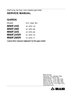
1.2 DIMENSIONS
1.2.1 MURELLE SYSTEM HE 12-20-25-30-35

5
1.2.2 MURELLE HE 25-30-35
170
135
385
=
=
92
70
70 70
70
=
=
R
M
G
E
U
15
760
65
700
125
ø 60/100
190
450
350
60
42,5
123
S3
Fig. 1/a
TABLE 2 - Minimum clearances
For ventilation For servicing
ABOVE THE APPLIANCE CASING 200 mm 300 mm
AT THE R.H.S. 15 m m 15 m m
AT THE L.H.S. 15 m m 15 m m
BELOW THE APPLIANCE CASING 200 mm 200 mm
IN FRONT OF THE APPLIANCE 350 mm 500 mm
TABLE 1 - Connections
R C.H. return 22 mm Compression
M C.H. flow 22 mm Compression
G Gas connection 15 mm Compression
E D.H.W. inlet 15 mm Compression
U D.H.W. outlet 15 mm Compression
S3 Condensation outlet ø 20

6
Models MURELLE
HE 25 HE 30 HE 35 System HE 12 System HE 20 System HE 25 System HE 30 System HE 35
Heat output
Nominal (80-60°C) kW 23.9 28.9 34.1 11.7 19.0 23.9 28.9 34.1
Nominal (50-30°C) kW 26.2 31.6 37.2 12.8 20.9 26.2 31.6 37.2
Reduced
G20 (80-60°C) kW 4.7 5.9 7.9 2.8 4.2 4.7 5.9 7.9
Reduced
G20 (50-30°C) kW 5.4 6.6 8.8 3.2 4.8 5.4 6.6 8.8
Reduced
G31 (80-60°C) kW 7.5 7.6 8.7 7.5 7.5 7.5 7.6 8.7
Reduced
G31 (50-30°C) kW 8.5 8.5 9.6 8.5 8.5 8.5 8.5 9.6
Heat input
Nominal kW 24.5 29.5 34.8 12.0 19.5 24.5 29.5 34.8
Reduced
G20/G31 kW 5.0/8.0 6.2/8.0 8.2/9.0 3.0/8.0 4.5/8.0 5.0/8.0 6.2/8.0 8.2/9.0
Max/min useful yield (80-60°C) % 94/97.5 95/98 96/98 94/97.5 94/97.5 94/97.5 95/98 96/98
Max/min useful yield (50-30°C) % 107/107 107/107 107/107 107/107 107/107 107/107 107/107 107/107
Useful yield at 30% of the load (50-30°C) % 107 107 107 107 107 107 107 107
Termal efficiency (CEE 92/42 directive)
★★★★ ★★★★ ★★★★ ★★★★ ★★★★ ★★★★ ★★★★ ★★★★
Losses after shutdown to 50°C (EN 483)
W/h 85 90 95 80 85 85 90 95
Supply voltage
V-Hz 230-50 230-50 230-50 230-50 230-50 230-50 230-50 230-50
Adsorbed power consumption
W 125 130 140 110 120 125 130 140
Electrical protection grade
IP X4D X4D X4D X4D X4D X4D X4D X4D
C.H. setting range
°C 20/80 20/80 20/80 20/80 20/80 20/80 20/80 20/80
Water content boiler
l 4.9 5.5 6.0 4.4 5.0 5.0 5.6 6.1
Maximum water head
bar 3 3 3 3 3 3 3 3
Maximum temperature
°C 85 85 85 85 85 85 85 85
Capacity of the heating expansion vessel l 8 10 10 8 8 8 10 10
Pressure of the heating expansion vessel bar 1 1 1 1 1 1 1 1
D.H.W. setting range
°C 30/60 30/60 30/60 -- -- -- -- --
D.H.W. flow rate (EN 625)
l/min 11.1 13.6 16.1 -- -- -- -- --
Continuous D.H.W. flow rate ∆t 30°C
l/min 11.4 13.8 16.3 -- -- -- -- --
Continuous D.H.W. flow rate ∆t 35°C
l/min 9.8 11.8 14.0 -- -- -- -- --
Minimum D.H.W. flow rate
l/min 2 2 2 -- -- -- -- --
D.H.W. pressure min/max
bar 0.2/7.0 0.2/7.0 0.2/7.0 -- -- -- -- --
D.H.W. pressure min. nom. power
bar 0.5 0.65 0.8 -- -- -- -- --
Exhaust fumes temperature at max flow rate (80-60°C)
°C 70 70 70 70 70 70 70 70
Exhaust fumes temperature at min. flow rate (80-60°C)
°C 65 65 65 65 65 65 65 65
Exhaust fumes temperature at max flow rate (50-30°C)
°C 40 40 40 40 40 40 40 40
Exhaust fumes temperature at min. flow rate (50-30°C)
°C 35 35 35 35 35 35 35 35
Smokes flow min/max
kg/h 9/42 11/50 14/60 5/21 8/33 9/42 11/50 14/60
CO
2 at max/min flow rate G20 % 9.0/9.0 9.0/9.0 9.0/9.0 9.0/9.0 9.0/9.0 9.0/9.0 9.0/9.0 9.0/9.0
CO
2 at max/min flow rate G31 % 10.0/10.0 10.0/10.0 10.0/10.0 10.0/10.0 10.0/10.0 10.0/10.0 10.0/10.0 10.0/10.0
CE certification
n° 1312BS5039
Category
II2H3P
Type B23P-53P/C13-33-43-53-83
NOx emission class
5 (< 30 mg/kWh)
Weight when empty
kg 43 57 69 31 42 42 56 68
Main burner nozzle
Quantity nozzles
n°11111111
G20 nozzle diameter
ø 5.0/3.7 7.0/5.0 8.5/5.2 4.0/3.1 5.0/3.7 5.0/3.7 7.0/5.0 8.5/5.2
Consumption at maximum/minimum flow rate
Maximum G20
m
3
/h 2.59 3.12 3.68 1.27 2.06 2.59 3.12 3.68
Minimum G20 m
3
/h 0.53 0.66 0.87 0.32 0.48 0.53 0.66 0.87
Maximum G31
kg/h 1.90 2.29 2.70 0.93 1.51 1.90 2.29 2.70
Minimum G31 kg/h 0.62 0.62 0.70 0.62 0.62 0.62 0.62 0.70
Gas supply pressure
G20/G31 mbar 20/37 20/37 20/37 20/37 20/37 20/37 20/37 20/37
1.3 TECHNICAL FEATURES

7
G
M
R
E
U
S3
21
19
1
3
18
4
5
9
8
12
13
6
7
17
25
15
16
24
20
23
22
14
10
1.4 FUNCTIONAL DIAGRAM
1
3
10
9
8
12
13
15
7
17
19
16
25
24
23
4
18
G
M
R
S3
MURELLE HE 25-30-35
MURELLE SYSTEM HE 12-20-25-30-35
KEY
1 Fan
3 Primary exchanger
4 Gas valve
5 D.H.W. heat exchanger
6 Diverter valve
7 Water flow meter
8 Aqua Guard Filter System
9 Safety thermostat 100°C
10 C.H. sensor (SM)
12 Pump with air release vent
13 Automatic bypass
14 D.H.W. (SS) sensor
15 Pressure transducer
16 Drain vent
17 3 BAR safety valve
18 Expansion vessel
19 Condensate trap
20 D.H.W. filter
21 ------
22 Hot water inlet isolation valve
23 Gas Isolation valve
24 CH flow isolation valve
25 CH return isolation valve
CONNECTIONS
R C.H. return
M C.H. flow
G Gas connection
E D.H.W. inlet
U D.H.W. outlet
S3 Condensation outlet
Fig. 2

8
11
10
9
8
7
6
4
3
2
1
19
18
17
16
15
14
13
12
5
Fig. 3
KEY
1 Control panel
2 Water flow meter
3 Aqua Guard Filter System
4 Condensate trap
5 Air pressure test point
6 Ignition transformer
7 Safety thermostat
8 C.H. sensor (SM)
9 Ignition electrode
10 Primary exchanger
11 Exhaust fumes sensor
12 Flue manifold
13 Expansion vessel
14 Ionisation electrode
15 F an
16 Gas valve
17 Automatic vent
18 Pump
19 Valve cover
21 Manual air vent (see 4.7.1)
1.5 MAIN COMPONENTS
19
20
18
17
16
15
14
13
12
11
10
9
8
7
6
5
3
4
2
1
MURELLE HE 25-30-35
MURELLE SYSTEM HE 12-20-25-30-35
KEY
1 Control panel
2 Water flow meter
3 Aqua Guard Filter System
4 Condensate trap
5 Air pressure test point
6 Ignition transformer
7 Safety thermostat
8 C.H. sensor (SM)
9 Ignition electrode
10 Primary exchanger
11 Exhaust fumes sensor
12 Flue manifold
13 Expansion vessel
14 Ionisation electrode
15 F an
16 Gas valve
17 Automatic vent
18 Pump
19 Valve cover
20 Pressure transducer
21 Manual air vent (see 4.7.1)
21
APRE
OPEN

9
The boiler must be installed in a fixed loca-
tion and only by specialized and qualified per-
son in compliance with all instructions con-
tained in this manual. The installation of this
boiler must be in accordance with the rele-
vant requirements of the current Gas
Safety (installation and use), the local build-
ing regulations, and and I.E.E. wiring regula-
tions. Detailled recommendations for air
supply are given in BS5440:2. The following
notes are for general guidance: it is not nec-
essary to have a purpose provided air vent
in the room or compartment in which the
appliance is installed.
2.1 ANTI-FREEZE FUNCTION
The boilers are equipped with anti-freeze
function which activates the pump and the
burner when the temperature of the water
contained inside the appliance drops to
below 6°C. The anti-freeze function ca only
operate if:
- the boiler is correctly connected to the
gas and electricity supply circuits;
- the boiler is constantly fed;
- the boiler ignition is not blocked;
- the essential components of the boiler
are all in working order
In these conditions the boiler is protected
against frost down to an environmental
temperature of -5°C.
ATTENTION: In the case of installation in a
place where the temperature drops below
0°C, the connection pipes must be pro-
tected.
2.2 FIXING THE WALL
MOUNTING BRACKET
– Mark the position of the two wall mount-
ing bracket fixing holes and the flue/air
duct hole on the appropriate wall(s).
– Drill a top two fixing holes using a 10 mm
masonry drill and fit the plastic plugs
provided.
– Accurately measure the wall thickness,
and note this dimension for later use.
– Secure the wall mounting bracket in
position using the screws provided.
Ensure that it is the correct way up, as
indicated in fig. 4.
2.3 CONNECTING UP SYSTEM
Before connecting the boiler it is recom-
mended that the system be flushed in
accordance to BS 7593, to eliminate any
foreign bodies that may be detrimental to
the operating efficiency of the appliance.
When connecting up the boiler the clearances
in fig 1 and 1/a should be respected. The boil-
er is supplied with a valve pack part number
5184 817.
A safety valve set at 3 bar is fitted to the
appliance, the discharge pipe provided
should be extended to terminate safely away
from the appliance and where a discharge
would not cause damage to persons or prop-
erty but would be detected. The pipe should
be a minimum of 15 mm Ø and should be
able to withstand boiling water, any should
avoid sharp corners or upward pipe runs
where water may be retained.
Gas Connection
The gas connection must be made using
seamless steel or copper pipe, galvanized and
with threaded joints provided with gaskets,
excluding three-piece connections, except for
initial and end connections. Where the piping
has to pass through walls, a suitable insulating
sleeve must be provided. When sizing gas pip-
ing, from the meter to the boiler, take into
account both the volume flow rates (con-
sumption) in m
3
/h and the relative density of
the gas in question.
The sections of the piping making up the sys-
tem must be such as to guarantee a supply of
gas sufficient to cover the maximum demand,
limiting pressure loss between the gas meter
and any apparatus being used to not greater
than 1.0 mbar for family II gases (natural gas).
An adhesive data badge is sited inside the
front panel; it contains all the technical data
identifying the boiler and the type of gas for
which the boiler is arranged.
2.3.1 Connection of condensation
water trap (fig. 5)
To ensure safe disposal of the condensate
produced by the flue gases, reference should
be made to BS6798:2000. The boiler incor-
porates a condensate trap which has a seal of
75mm, therefore no additional trap is
required. The condensate should ideally be dis-
charged internally into an internal waste
pipe(washing machine/sink waste) or a soil
pipe to avoid the risk of freezing. External pipe
runs should be avoided, but if it is necessary,
the pipework should be at least 32mm and
protected from the risc of freezing with a
waterproof insulation and the length kept to a
minimum and not exceeding 3 m. termination
should be into an external gully or purpose
made soakaway.
NOTE: All pipework must have a continuous
fall from the boiler and must be resistant to
corrosion by condensate, copper
or steel is
NOT suitable. It should be noted that the
connection of a condensate pipe to a drain
may be subject to local building control
requirements.
2 INSTALLATION
1
2
3
4
KEY
1 Wall mounting bracket
2 Plastic wall plug (2 Off)
3 Woodscrew (2 Off)
4 Washer (2 Off)
Fig. 4
Fig. 5

10
2.3.2 Requirements for sealed water
systems MURELLE HE
The heating system design should be based
on the following information:
a) The available pump head is given in fig. 16.
b) The burner starts when the C.H. flow
reaches 400÷450 l/h. This safety condi-
tion is ensured by the flow switch.
c) The appliance is equipped with an internal
by-pass that operates with system heads
(H) greater than 3 m. The maximum flow
through the by-pass is about 300 l/h. If
thermostatic radiator valves are to be
installed, at least one radiator should be
without a thermostatic valve (usually the
bathroom radiator).
d) A sealed system must only be filled by a
competent person using one of the
approved methods shown in fig. 5/a. The
system design should incorporate the
connections appropriate to one of these
methods.
2.3.3 Requirements for sealed water
systems MURELLE SYSTEM HE
The heating system design should be based
on the following information:
a) The available pump head is given in fig. 16.
b) The appliance is equipped with an internal
by-pass that operates with system heads
(H) greater than 3 m. The maximum flow
through the by-pass is about 300 l/h. If
thermostatic radiator valves are to be
installed, at least one radiator should be
without a thermostatic valve (usually the
bathroom radiator).
2.4 CHARACTERISTICS OF FEEDWATER
– All recirculatory systems will be subject to
corrosion unless an appropriate water
treatment is applied. This means that the
efficiency of the system will deteriorate as
corrosion sludge accumulates within the
system, risking damage to pump and
valves, boiler noise and circulation prob-
lems.
– For optimum performance after installa-
tion this boiler and its associated central
heating system must be flushed in accor-
dance with the guidelines given in BS
7593 “Treatment of water in domestic
hot water central heating systems”.
– This must involve the use of a proprietary
cleanser, such as Sentinel X300 or X400,
or Fernox Superfloc. Full instructions are
supplied with the products, but for imme-
diate information please contact GE Betz
(0151 420 9563) or Fernox (01799 550
811) directly.
– For long term protection against corro-
sion and scale, after flushing it is recom-
mended that an inhibitor such as Sentinel
X100, or Fernox MB-1 or Copal is dosed
in accordance with the guidelines given in
BS 7593.
Failure to flush and add inhibitor to the
system may invalidate the appliance
warranty.
– It is important to check the inhibitor con-
centration after installation, system modi-
fication and at every service in accor-
dance with the manufacturer’s instruc-
tions. (Test kits are available from inhibitor
stockists).
– At every service the Aquaguard Filter
(4.5.2) should be checked and cleaned.
2.5
INSTALLATION OF COAXIAL DUCT
(ø 60/100 - ø 80/125)
The axial suction and discharge pipes are sup-
plied in a special kit (that can be purchased
separately) along with assembly instructions.
C33
6
5
3
2
C43
3
4
2
x
y
x + y = L (m)
H (m)
C13
1
2
1
L (m)
2
Fig. 6
LIST OF ø 60/100 ACCESSORIES
1
Coaxial duct kit L. 790 code 8096250
2a Extension L. 1000 code 8096150
2b Extension L. 500 code 8096151
3 Vertical extension L. 140 with coupling code 8086950
5 Tile for joint code 8091300
6 Terminal for roof exit L. 1285 code 8091205
Model Length of pipe Length of pipe
ø 60/100 ø 80/125
HV H V
Min Max Min Max
SYSTEM HE 12 6 m 1.3 m 8 m 12 m 1.2 m 15 m
SYSTEM HE 20 6 m 1.3 m 8 m 12 m 1.2 m 15 m
SYSTEM HE 25 - HE 25 6 m 1.3 m 8 m 12 m 1.2 m 15 m
SYSTEM HE 30 - HE 30 5 m 1.3 m 7 m 10 m 1.2 m 13 m
SYSTEM HE 35 - HE 35 4 m 1.3 m 6 m 8 m 1.2 m 11 m
LIST OF ø 80/125 ACCESSORIES
1 Coaxial duct kit L. 785 code 8096253
2a Extension L. 1000 code 8096171
2b Extension L. 500 code 8096170
3 Adapter for ø 80/125 code 8093150
5 Tile for joint code 8091300
6 Terminal for roof exit L. 1285 code 8091205
H (Horizontal) m
V (Vertical) m
IMPORTANT:
- The insertion of each additional 90° bend with a diameter of 60/100 (code 8095850)
reduces the available section by 1.5 meters.
- The insertion of each additional 90° bend with a diameter of 80/125 (code 8095870)
reduces the available section by 2 meters.
- Each additional 45° curve installed a diameter of 60/100 (code 8095550) reduces the
available length by 1.0 metres.
- Each additional 45° curve installed a diameter of 80/125 (code 8095970) reduces the
available length by 1.0 metres.
HORIZONTAL FLUES MUST BE LEVEL
NOTE: Before connecting accessories, it is always advisable to lubricate the internal part of
the gaskets with silicon products. Avoid using oils and greases.
ALTERNATIVE METHODS OF
FILLING A SEALED SYSTEM
Fig. 5/a

11
The diagrams of fig. 6 illustrate
some exam-
ples of different types of discharge modali-
ties allowed and the maximum lengths that
can be reached.
2.6 INSTALLATION OF SEPARATE
DUCTS (ø 80)
The kit with dedicated pipes enables to
separate the exhaust fumes pipes from the
air suction pipes (Fig. 7):
- The kit with dedicated ø 80 pipes, code
8089912, includes a SUCTION DIAPH-
RAGM THAT IS NOT used for these
models. To be able to use the air tap, cut
its base with a tool (A) and assemble it
(B).
The maximum overall length, resulting
from the sum of all the suction and
discharge pipes, is determined by the
load losses of the single connected acces-
sories and should not exceed 10 mm H2O
(version HE 12) - 13 mm H2O (version HE
20) - 15 mm H2O (version HE 25-30-35)
(ATTENTION: the total length of each pipe
should not exceed 50 m, even if the total
loss is belo
w the maximum applicable
loss.)
See Table 3 for information on the load los-
ses of single accessories and the example
Fig. 7
KEY
CA Inlet
CS Outlet
Example of allowable installation “HE 25” calculation in that the sum of the head losses of
the single fittings is less than 15.0 mm H
2
O:
Inlet Outlet
9
m horizontal pipe
ø 80 x 0.15 1.35 –
9
m horizontal pipe
ø 80 x 0.15 – 1.35
n° 2
90° elbows
ø 80 x 0.20 0.40 –
n° 2
90° elbows
ø 80 x 0.25 – 0.50
n° 1 terminal ø 80 0.10 0.25
Total head loss
1.85 + 2.10 = 3.95
mm H
2
O
TABLE 3 - ACCESSORIES ø 80
Accessories ø 80 Total head loss (
mm H
2
O)
HE 12 HE 20 HE 25 HE 30 HE 35
Inlet Outlet Inlet Outlet Inlet Outlet Inlet Outlet Inlet Outlet
Coaxial duct kit – – – – – – – – – –
90° elbow MF 0.05 0.10 0.15 0.20 0.20 0.25 0.25 0.30 0.30 0.40
45° elbow MF 0.05 0.05 0.10 0.10 0.15 0.15 0.20 0.20 0.25 0.25
Extension L. 1000 (horizontal) 0.05 0.05 0.10 0.10 0.15 0.15 0.20 0.20 0.25 0.25
Extension L. 1000 (vertical) 0.05 0.05 0.10 0.10 0.15 0.15 0.20 0.20 0,25 0.25
Wall terminal 0.05 0.15 0.05 0.20 0.10 0.25 0.10 0.35 0.15 0.50
Wall coaxial exhaust
*
Roof outlet terminal * 0.25 0.05 0.50 0.05 0.80 0.10 1.10 0.15 1.50 0.20
* The loss of the accessorie in aspiration concludes the collector code 8091400/01
OPERAZIONE DA ESEGUIRE
SOLO NEL MONTAGGIO DEL
KIT Ø 80 COD. 8089912
A
B
4
1
3
2
6
4
5
C
Fig. 8
KEY
1 ø 125 Gasket
2 Fumes exhausts flange with tap
3 Fastening screw
4 ø 108 Gasket
148
112
ø 80
ASSEMBLY OF THE KIT ø 80 code 8089912
277,5
67,5
169
134
236
CS
CA
CA

12
of Fig. 8 for information on how to calculate
load losses.
2.6.1 Separate ducts kit
The diagrams of Figure 9 show a few examples
of the permitted exhausts configurations.
2.7 POSITIONING THE
OUTLET TERMINALS
The outlet terminals for forced-draught
appliances may be located in the external
perimeter walls of the building.
To provide some indications of possible solu-
tions, Table 4 gives the minimum distances
to be observed, with reference to the type
of building shown in fig. 10.
2.8 ELECTRICAL CONNECTION
The boiler is supplied with an electric cable.
Should this require replacement, it must be
purchased exclusively from SIME.
The electric power supply to the boiler must
be 230V - 50Hz single-phase through a
fused main switch, with at least 3 mm spa-
cing between contacts. Respect the L and N
polarities and the earth connection.
NOTE: SIME declines all responsibility for
– If the terminal discharges into a pathway or passageway check
that combustion products will not cause nuisance and that the
terminal will not obstruct the passageway.
– Where the lowest part of the terminal is fitted less than 2 m
(78 in) above ground, above a balcony or above a flat roof to
which people have access, the terminal MUST be protected by
a purpose designed guard. Terminal guards are available from
Quinnell, Barrett, and Quinnell, Old Kent Road, London. State
model C2, (G.C. Part No 382946).
– Where the terminal is fitted within 850 mm (34 in) of a plastic
or painted gutter, or 450 mm (18 in) of painted eaves, an alu-
minium shield at least 1,500 mm (59 in) long must be fitted to
the underside of the painted surface.
– The air inlet/outlet flue duct MUST NOT be closer than 25 mm
(1 in) to combustible material.
– In certain weather conditions the terminal may emit a plume of
steam. This is normal but positions where this would cause a
nuisance should be avoided.
Terminal position Minimum spacing
A Directly below an openable window, air vent
or any other ventilation opening 300 mm 12 in
B Below guttering, drain pipes or soil pipes 75 mm 3 in
C/D Below eaves, balconies or carport roof 200 mm 8 in
E From vertical drain pipes or soil pipes 75 mm 3 in
F From internal or external corners 300 mm 12 in
G Above adjacent ground, roof or balcony level 300 mm 12 in
H From a boundary or surface facing the boiler 600 mm 24 in
I From a terminal facing the terminal 1,200 mm 48 in
J From an opening in the carport
(eg door, window into dwelling) 1,200 mm 48 in
K Vertically from a terminal on the same wall 1,500 mm 60 in
L Horizontally from a terminal on the same wall 300 mm 12 in
M Horizontally from a vertical terminal to a wall 300 mm 12 in
N Horizontally from an openable window or other opening 300 mm 12 in
P Above an openable window or other opening 300 mm 12 in
Q From an adjacent vertical terminal 600 mm 24 in
TABLE 4
9
C
C33
11
10
3
1
1
3
3
7
3
12
12
12
Fig. 10
Fig. 9
C13
3
2
3
1
14
12
13
12
NOTE
Before connecting accessories, it is always advisable
to lubricate the internal part of the gaskets with sili-
con products. Avoid using oils and greases.
LIST OF ø 80 ACCESSORIES
1 Coaxial duct kit code 8089912
3 a Extension L. 1000 code 8077351 (6 pz.)
3 b Extension L. 500 code 8077350 (6 pz.)
7 a Additional 45° MF curve code 8077451(6 pz.)
7 b Additional 90° MF curve code 8077450 (6 pz.)
9 Manifold, code 8091400
10 Tile for joint code 8091300
11 Terminal for roof exit L. 1381 code 8091204
12 --------
13 Union suction/exhaust code 8091401
14 Coaxial exhaust ø 80/125 L. 885 code 8091210

13
2.8.5 Use with different
electronic systems
Some examples are given below of boiler
systems combined with different electronic
systems. Where necessary, the parame-
ters to be set in the boiler are given. The
electrical connections to the boiler refer to
the wording on the diagrams (figg. 11-
11/a).
The zone valve control starts at every
demand for heating of the zone 1 (it is from
part of the TA1 or the CR).
Description of the letters indicating the
components shown on the system dia-
grams:
M C.H. flow
R C.H. return
CR Remote control CR 73
SE External temperature sensor
TA 1-2-3-4 Zone room thermostat
CT 1-2 Zone room thermostat internal
time clock
VZ 1-2 Zone valve
RL 1-2-3-4 Zone relay
Sl Hydraulic separator
P 1-2-3-4 Zone pump
IP Floor system
EXP Expansion card (code 8092233)
VM Three-way mixer valve
R
M
SE
TA
CR
TA1
CR
SE
injury or damage to persons, animals or
property, resulting from the failure to pro-
vide for proper earthing of the appliance.
2.8.1 Room thermostat
connection
The heat demand can be by a "clean con-
tact" (conforming to EN607301), room
stat or programmer connected to the "TA"
connection (Fig. 11-11/a), CN6 terminals
7 & 8 after removing the link
Or
A 230v switched demand to terminal 14
CN7 and removal of the "TA" link on termi-
nals 7 & 8 on CN6.
Note - a permanent power supply must
be maintained.
2.8.2 Climatic regulator CR 53
connection (optional)
The boiler is designed for connectio to a cli-
matic regulator, supplied on request (code
8092227), for the management of a hea-
ting circuit. The electronic card will conti-
nue to manage information visualisation,
the setting of the sanitary set and the hea-
ting of the second circuit, and the boiler
parameters by means of the keys on the
control panel. For installation and use of
the climatic regulator, follow the instruc-
tions included in the packaging.
NOTE: Reset parameter 10 to 2 (PAR 10
= 2).
2.8.3 Remote control CR 73
connection (optional)
The boiler is designed for connection to a
remote control unit, supplied on request
(code 8092226).
The remote control unit CR 73 allows for
complete remote control of the boiler,
except release of the boiler. The boiler
display will show the following message:
For installation and use of the remote con-
trol, follow the instructions in the package.
NOTE: Ensure PAR 10 set to 1 (PAR 10 =
1).
2.8.4 External sensor connection
The boiler is designed for connection to an
external temperature sensor, supplied on
request (code 8094101) in conjunction
with remote control (code 8092226),
which can automatically regulate the tem-
perature value of the boiler output accor-
ding to the external temperature.
For installation, follow the instruction in the
package.
It is possible to make corrections to the
values read by the drill acting on the PAR
11.
1 BASIC SYSTEM
SYSTEM WITH A DIRECT ZONE AND ROOM THERMOSTAT, OR
WITH A CLIMATIC REGULATOR CR 53 (Code 8092227) OR WITH
REMOTE CONTROL CR 73 (Code 8092226) AND EXTERNAL SEN-
SOR (Code 8094101)
PARAMETERS SETTINGS
If using CR 53 set parameter
10 to 2 (PAR 10 = 2)

14
TA1
SE
R
M
SE
TA
VZ
TA1
VZ1
TA2
VZ2
R
M
SE
TA1
TA2
TA1
SE
TA
P2
RL
SI
RL1
RL2
P1
P
TA2
SE
R
M
SE
TA
VZ
TA1
VZ1
TA2
VZ2
CR
CR
2 BASIC SYSTEM
MULTI-ZONE SYSTEM WITH PUMP, ROOM THERMOSTAT AND EXTERNAL SENSOR (Code 8094101)
3 BASIC SYSTEM
MULTI-ZONE SYSTEM WITH PUMP, ROOM THERMOSTAT AND EXTERNAL SENSOR (Code 8094101)
4 BASIC SYSTEM
MULTI-ZONE SYSTEM WITH VALVE, ROOM THERMOSTAT, REMOTE CONTROL CR 73 (Code 8092226)
AND EXTERNAL SENSOR (Code 8094101)
PARAMETERS SETTINGS
To use the remote control
(CR) as remote control panel
for the boiler rather than as
room reference, set:
PAR 7 = 0

15
TA2
SE
R
M
SE
VZ
VZ1
TA2
VZ2
CR
CR
VZ1
TA1
PARAMETER SETTING
To use the remote control (CR) as room reference for a zone, set: PAR 7 = 1
Set the opening time of the zone valve VZ: PAR 33 = “OPENING TIME”
SI
R
M
SE
TA1
TA2
TA2
SE
TA
P2
RL
RL1
RL2
P1
P
CR
CR
PARAMETER SETTING
To use the remote control (CR) as room reference for a zone, set: PAR 7 = 1
5 BASIC SYSTEM
MULTI-ZONE SYSTEM WITH VALVE, ROOM THERMOSTAT, REMOTE CONTROL CR 73 (Code 8092226)
AND EXTERNAL SENSOR (Code 8094101)
6 BASIC SYSTEM
MULTI-ZONE SYSTEM WITH PUMP, ROOM THERMOSTAT, REMOTE CONTROL CR 73 (Code 8092226)
AND EXTERNAL SENSOR (Code 8094101)

16
R
M
SE
CT2
TA1
SE
CT1
SI
RL2
P2
P1
TA2
RL1
ZONA
GIORNO
(70°C)
ZONA
NOTTE
(50°C)
8 SYSTEM WITH DOUBLE TEMPERATURE OUTPUT
MULTI-ZONE SYSTEM WITH PUMP, ROOM THERMOSTAT INTERNAL TIME CLOCK AND EXTERNAL
SENSOR (Code 8094101)
R
M
SE
CT2
TA1
SE
CT1
TA2
VZ1
VZ2
ZONA
GIORNO
(70°C)
ZONA
NOTTE
(50°C)
DURING NIGHT TIME THE BOILER USES A LOWER OUTPUT TEMPERATURE IF DIFFERENT TIMES HAVE BEEN SET FOR DAY AND NIGHT
AREAS:
- with external sensor, set the climatic curve of the day zone 1 with PAR 25 and the night zone at PAR 26.
- without external sensor, gain access to setting the day zone 1 by pressing the key and change the value with the keys and
. Gain access to setting the night zone by pressing the key twice and changing the value with the keys and
.
7 SYSTEM WITH DOUBLE TEMPERATURE OUTPUT
MULTI-ZONE SYSTEM WITH VALVE, ROOM THERMOSTAT INTERNAL TIME CLOCK AND EXTERNAL
SENSOR (Code 8094101)
DAY
ZONE
(70°C)
NIGHT
ZONE
(50°C)
DAY
ZONE
(70°C)
NIGHT
ZONE
(50°C)

17
R
M
SE
TA2
TA1
SE
TA1
SI
RL2
P2
P1
TA2
CR
CR
EXP
VM
EXP
IP
R
M
SE
TA3
TA1
SE
SI
RL3
P3
P2
TA2
IP
EXP
VM
EXP
IP
P4
TA4
RL4
TA1
TA2
9 SYSTEM WITH MIXER VALVE
SYSTEM WITH ONE DIRECT ZONE AND ONE MIXED ZONE
10 SYSTEM WITH MIXER VALVE
SYSTEM WITH TWO DIRECT ZONES AND TWO MIXED ZONES
PARAMETERS SETTINGS
To use the remote control
(CR) as remote control panel
for the boiler rather than as
room reference, set:
PAR 7 = 0

18
2.9 BOILER ELECTRICAL “MURELLE SYSTEM HE 12-20-25-30-35”
Fig. 11
KEY
F1-2 Fuse (4 AT)
TRA Ignition transformer
PI Pump
VFan
EA Ignition electrode
ER Detection electrode
EV1-2 Gas valve coil
TS Safety thermostat
SF Exhaust fumes probe
TFU Thermal fuse
SM Heating sensor
FL Water flow switch
TPA Pressure transducer
TA1 Zone 1 environment thermostat
TA2 Zone 2 environment thermostat
CR Remote control CR 73 (optional)
SE External sensor (optional)
OP Internal time clock (optional)
EXP Expansion card
PR/AR Recirculation pump control
or remote alarm
VZ Zone valve
AUX Auxiliary connection
NOTE: Connect TA1 to the clamps 7-8
after having removed the bridge.
CONNECTOR SPARE PART CODES:
CN1 code 6316212
CN2 code 6316214
CN3 code 6316210
CN4 code 6316203
CN6 code 6316202
CN7 code 6316204
CN10 cod. 6316227
CN11 cod. 6316226
CN12 code 6299991
CN13 code 6316212
CN14 code 6316213
230 Vac
230 Vac
230 Vac
230 Vac

19
2.10 BOILER ELECTRICAL “MURELLE HE 25-30-35”
Fig. 11/a
KEY
F1-2 Fuse (4 AT)
TRA Ignition transformer
PI Pump
VFan
EA Ignition electrode
ER Detection electrode
EV1-2 Gas valve coil
TS Safety thermostat
SF Exhaust fumes probes
TFU Thermal fuse
VP Diverter valve microswitch
SM Heating sensor
FL Water flow switch
SS D.H.W. sensor
TPA Pressure transducer
TA1 Zone 1 environment thermostat
TA2 Zone 2 environment thermostat
ST Solar heat sensor
CR Remote control CR 73 (optional)
SE External sensor (optional)
OP Internal time clock (optional)
EXP Expansion card
AR Remote alarm
VZ Zone valve
AUX Auxiliary connection
NOTE: Connect TA1 to the clamps 7-8
after having removed the bridge.
CONNECTOR SPARE PART CODES:
CN1 code 6316212
CN2 code 6316211
CN3 code 6316210
CN4 code 6316203
CN5 code 6316200
CN6 code 6316202
CN7 code 6316204
CN10 cod. 6316227
CN11 cod. 6316226
CN12 code 6299991
CN13 code 6316212
CN14 code 6316213
230 Vac
230 Vac
230 Vac
230 Vac

20
3 CHARACTERISTICS
3.1 CONTROL PANEL
5
3
1
2
4
DESCRIPTION OF DISPLAY ICONS
SUMMER MODE ICON
WINTER MODE ICON
D.H.W. MODE ICON
HEATING MODE ICON
1 = First circuit heating system
2 = Second circuit heating system (optional)
GRADED POWER SCALE
The segments of the bar light up in proportion to boiler
power
output .
2 - DESCRIPTION OF CONTROLS
ON/STANDBY
ON = The boiler is on
STANDBY = The boiler is off, but the protection func-
tions are active.
SUMMER MODE KEY
When this key is pressed, the boiler operates only
when D.H.W. is requested.
WINTER MODE KEY
When this key is pressed, the boiler provides heating
and D.H.W.
D.H.W TEMP KEY
When this key is pressed, the temperature of the
D.H.W. is shown on the display.
HEATING TEMP KEY
The first time the key is pressed, the temperature of
heating circuit 1 is shown.
The second time the key is pressed, the temperature
of heating circuit 2 is shown.
RE-SET KEY
Press to reset a resettable error.
INCREASE AND DECREASE KEY
By pressing this key the set value increases or decrea-
ses.
BOILER FUNCTIONING AND LOCKOUT ICON
RE-SET REQUIRED
CHIMNEY SWEEP ICON
SECONDARY DIGITS
The boiler displays the value of the pressure of the
system (correct value is between 1 and 1.5 bar)
3 - KEYS RESERVED FOR THE INSTALLER
(access to INST and OEM parameters)
4 - LUMINOUS BAR
Blue = Operating normally
Red = Operating error
5 - PROGRAMMING CLOCK (optional)
Mechanical clock (code 8092228) the digital clock
(code 8092229).
Analogic RF time programmer (code 8092231)
the digital RF time programmer (code 8092232).
MAIN DIGITS
The boiler displays the values set, the state of
anomaly and the external temperature
Fig. 12
PC CONNECTION
To be used only with the SIME programming kit and only
by authorised personnel. Do not connect other electro-
nic devices (cameras, telephones, mp3 players, etc.)
Use a tool to remove the cap and reinsert after use.
ATTENTION: Communication port
sensitive to electrostatic charges.
Before use, it is advisable to touch an earthed metallic
surface to discharge static electricity.
INFORMATION KEY
This key can be pressed several times to view the para-
meters.
CHIMNEY SWEEP KEY
This key can be pressed several times to view the para-
meters.
DECREASE KEY
This key changes the default settings.
INCREASE KEY
This key changes the default settings.
/