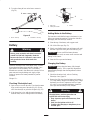
Toro Z153 Z Master, With 52" SFS Side Discharge Mower User manual
- Category
- Lawnmowers
- Type
- User manual

Operator’s Manual
Domestic English (EN)
Form No. 3326–673
Z153
Z–Master
with 52 SFS Side Discharge Mower
Model No. 74198—210000001 and Up

2
All Rights Reserved
Printed in the USA
2000 by The Toro Company
8111 Lyndale Avenue South
Bloomington, MN 55420-1196
The engine exhaust from this product contains
chemicals known to the State of California to
cause cancer, birth defects, or other reproductive
harm.
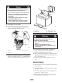
Warning
Because in some areas there are local, state, or federal
regulations requiring that a spark arrester be used on the
engine of this mower, a spark arrester is incorporated with
the muffler assembly.
Important This engine is equipped with a spark
arrester muffler. It is a violation of California Public
Resource Code Section 4442 to use or operate this engine
without a spark arrester muffler on any forest–covered,
brush–covered or grass–covered land. Other states or
federal areas may have similar laws.
This spark ignition system complies with Canadian
ICES-002.
Ce système d’allumage par étincelle de véhicule est
conforme à la norme NMB-002 du Canada.
The enclosed Engine Owner’s Manual is supplied for
information regarding The U.S. Environmental
Protection Agency (EPA) and the California Emission
Control Regulation of emission systems, maintenance
and warranty.
Keep this engine Owner’s Manual with your unit.
Should this engine Owner’s Manual become damaged
or illegible, replace immediately. Replacements may be
ordered through the engine manufacturer.
Contents
Page
Introduction 3. . . . . . . . . . . . . . . . . . . . . . . . . . . . . . . .
Safety 3. . . . . . . . . . . . . . . . . . . . . . . . . . . . . . . . . . . . .
Safe Operating Practices 3. . . . . . . . . . . . . . . . . . .
Toro Mower Safety 5. . . . . . . . . . . . . . . . . . . . . . .
Slope Chart 7. . . . . . . . . . . . . . . . . . . . . . . . . . . . . .
Safety and Instruction Decals 9. . . . . . . . . . . . . . .
Gasoline and Oil 12. . . . . . . . . . . . . . . . . . . . . . . . . . . .
Recommended Gasoline 12. . . . . . . . . . . . . . . . . . .
Using Stabilizer/Conditioner 12. . . . . . . . . . . . . . . .
Filling the Fuel Tank 12. . . . . . . . . . . . . . . . . . . . . .
Check Engine Oil Level 12. . . . . . . . . . . . . . . . . . . .
Assembly 13. . . . . . . . . . . . . . . . . . . . . . . . . . . . . . . . . .
Loose Parts 13. . . . . . . . . . . . . . . . . . . . . . . . . . . . . .
Install Drive Wheels 13. . . . . . . . . . . . . . . . . . . . . .
Tire Pressure 13. . . . . . . . . . . . . . . . . . . . . . . . . . . . .
Install Seat Retaining Rod 13. . . . . . . . . . . . . . . . . .
Page
Install Motion Control Levers 14. . . . . . . . . . . . . . .
Activate the Battery 14. . . . . . . . . . . . . . . . . . . . . . .
Install Battery 15. . . . . . . . . . . . . . . . . . . . . . . . . . . .
Hydraulic System 16. . . . . . . . . . . . . . . . . . . . . . . . .
Greasing the Bearings 16. . . . . . . . . . . . . . . . . . . . .
Check the Leveling of Mower Deck 17. . . . . . . . . .
Check Side Discharge Chute 17. . . . . . . . . . . . . . . .
Check Engine Oil Level 17. . . . . . . . . . . . . . . . . . . .
Operation 17. . . . . . . . . . . . . . . . . . . . . . . . . . . . . . . . . .
Think Safety First 17. . . . . . . . . . . . . . . . . . . . . . . .
Controls 17. . . . . . . . . . . . . . . . . . . . . . . . . . . . . . . .
Parking Brake 18. . . . . . . . . . . . . . . . . . . . . . . . . . . .
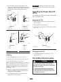
Starting and Stopping the Engine 18. . . . . . . . . . . .
Operating the Power Take Off (PTO) 19. . . . . . . . .
The Safety Interlock System 19. . . . . . . . . . . . . . . .
Testing the Safety Interlock System 20. . . . . . . . . .
Driving Forward or Backward 20. . . . . . . . . . . . . . .
Stopping the Machine 21. . . . . . . . . . . . . . . . . . . . .
Instruments 21. . . . . . . . . . . . . . . . . . . . . . . . . . . . . .
Fuel Tanks 21. . . . . . . . . . . . . . . . . . . . . . . . . . . . . .
Adjusting Height-of-Cut 21. . . . . . . . . . . . . . . . . . .
Adjusting Anti-Scalp Rollers 22. . . . . . . . . . . . . . . .
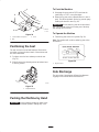
Positioning the Seat 23. . . . . . . . . . . . . . . . . . . . . . .
Pushing the Machine by Hand 23. . . . . . . . . . . . . . .
Side Discharge 23. . . . . . . . . . . . . . . . . . . . . . . . . . .
Transporting Machines 24. . . . . . . . . . . . . . . . . . . .
Loading Machines 24. . . . . . . . . . . . . . . . . . . . . . . .
Tips for Mowing Grass 25. . . . . . . . . . . . . . . . . . . .
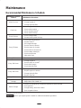
Maintenance 26. . . . . . . . . . . . . . . . . . . . . . . . . . . . . . . .
Recommended Maintenance Schedule 26. . . . . . . .
Cutting Blades 27. . . . . . . . . . . . . . . . . . . . . . . . . . .
Cleaning the Cooling System 29. . . . . . . . . . . . . . .
Air Cleaner 29. . . . . . . . . . . . . . . . . . . . . . . . . . . . . .
Engine Oil 30. . . . . . . . . . . . . . . . . . . . . . . . . . . . . .
Spark Plug 32. . . . . . . . . . . . . . . . . . . . . . . . . . . . . .
Fuel Filter 32. . . . . . . . . . . . . . . . . . . . . . . . . . . . . . .
Fuel Tank 33. . . . . . . . . . . . . . . . . . . . . . . . . . . . . . .
Servicing the Spark Arrester 33. . . . . . . . . . . . . . . .
Greasing and Lubrication 33. . . . . . . . . . . . . . . . . . .
Greasing the Bearings 34. . . . . . . . . . . . . . . . . . . . .
Hydraulic System 34. . . . . . . . . . . . . . . . . . . . . . . . .
Tire Pressure 36. . . . . . . . . . . . . . . . . . . . . . . . . . . . .
Castor Pivot Bearing Adjustment 36. . . . . . . . . . . .
Wheel Hub Slotted Nut 37. . . . . . . . . . . . . . . . . . . .
Mower Leveling 37. . . . . . . . . . . . . . . . . . . . . . . . . .
Adjusting Push Arms 38. . . . . . . . . . . . . . . . . . . . . .
Throttle Lever Adjustment 38. . . . . . . . . . . . . . . . .
Clean Under Deck 39. . . . . . . . . . . . . . . . . . . . . . . .
Belt Inspection 39. . . . . . . . . . . . . . . . . . . . . . . . . . .

3
Page
Replacing the Deck Belt 39. . . . . . . . . . . . . . . . . . .
Replacing the Pump Drive Belt 40. . . . . . . . . . . . . .
Adjusting Motion Controls 40. . . . . . . . . . . . . . . . .
Adjusting Parking Brake 42. . . . . . . . . . . . . . . . . . .
Fuse 42. . . . . . . . . . . . . . . . . . . . . . . . . . . . . . . . . . .
Battery 43. . . . . . . . . . . . . . . . . . . . . . . . . . . . . . . . .
Waste Disposal 44. . . . . . . . . . . . . . . . . . . . . . . . . . .
Mercury Tilt Switch 44. . . . . . . . . . . . . . . . . . . . . . .
Mercury Tilt Switch Disposal 44. . . . . . . . . . . . . . .
Replacing the Grass Deflector 44. . . . . . . . . . . . . . .
Wiring Diagram 46. . . . . . . . . . . . . . . . . . . . . . . . . .
Cleaning and Storage 47. . . . . . . . . . . . . . . . . . . . . .
Troubleshooting 48. . . . . . . . . . . . . . . . . . . . . . . . . . . . .
The Toro Total Coverage Guarantee 52. . . . . . . . . . . . .
Introduction
Thank you for purchasing a Toro product.
All of us at Toro want you to be completely satisfied with
your new product, so feel free to contact your local
Authorized Service Dealer for help with service, genuine
replacement parts, or other information you may require.
Whenever you contact your Authorized Service Dealer or
the factory, always know the model and serial numbers of
your product. These numbers will help the Service Dealer
or Service Representative provide exact information about
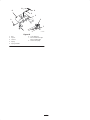
your specific product. You will find the model and serial
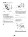
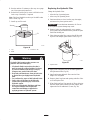
number plate at the location shown in Figure 1.
1
m-3648
Figure 1
1. Model and serial number plate
For your convenience, write the product model and serial
numbers in the space below.
Model No:
Serial No.
Read this manual carefully to learn how to operate and
maintain your product correctly. Reading this manual will
help you and others avoid personal injury and damage to
the product. Although we design, produce and market
safe, state-of-the-art products, you are responsible for
using the product properly and safely. You are also
responsible for training persons, who you allow to use the
product, about safe operation.
The warning system in this manual identifies potential
hazards and has special safety messages that help you and
others avoid personal injury, even death. Danger,
Warning, and Caution are signal words used to identify
the level of hazard. However, regardless of the hazard, be
extremely careful.
Danger signals an extreme hazard that will cause serious
injury or death if the recommended precautions are not
followed.
Warning signals a hazard that may cause serious injury or
death if the recommended precautions are not followed.
Caution signals a hazard that may cause minor or
moderate injury if the recommended precautions are not
followed.
Two other words are also used to highlight information.
Important calls attention to special mechanical
information, and Note emphasizes general information
worthy of special attention.
Determine the left and right side of the machine from the
normal operating position.
Safety
This machine meets or exceeds the B71.4 1999
specifications of the American National Standards
Institute, in effect at time of production.
Note: The addition of certain attachments that do not
meet American National Standards Institute certification
will cause noncompliance of this machine.
Improper use or maintenance by the operator or owner
can result in injury. To reduce the potential for injury,
comply with these safety instructions and always pay
attention to the safety alert symbol, which means
CAUTION, WARNING, or DANGER—“personal
safety instruction.” Failure to comply with the
instruction may result in personal injury or death.
Safe Operating Practices
The following instructions are from ANSI standard
B71.4—1999.

4
Training
• Read the Operator’s Manual and other training
material. If the operator(s) or mechanic(s) can not read
English it is the owner’s responsibility to explain this
material to them.
• Become familiar with the safe operation of the
equipment, operator controls, and safety signs.
• All operators and mechanics should be trained. The
owner is responsible for training the users.
• Never let children or untrained people operate or
service the equipment. Local regulations may restrict
the age of the operator.
• The owner/user can prevent and is responsible for
accidents or injuries occurring to himself or herself,
other people or property.
Preparation
• Evaluate the terrain to determine what accessories and
attachments are needed to properly and safely perform
the job. Only use accessories and attachments
approved by the manufacturer.
• Wear appropriate clothing including hard hat, safety
glasses and ear protection. Long hair, loose clothing or
jewelry may get tangled in moving parts.
• Inspect the area where the equipment is to be used and
remove all objects such as rocks, toys and wire which
can be thrown by the machine.
• Use extra care when handling gasoline and other fuels.
They are flammable and vapors are explosive.
• Use only an approved container
• Never remove gas cap or add fuel with engine
running. Allow engine to cool before refueling.
Do not smoke.
• Never refuel or drain the machine indoors.
• Check that operator’s presence controls, safety
switches and shields are attached and functioning
properly. Do not operate unless they are functioning
properly.
Operation
• Never run an engine in an enclosed area.
• Only operate in good light, keeping away from holes
and hidden hazards.
• Be sure all drives are in neutral and parking brake is
engaged before starting engine. Only start engine from
the operator’s position. Use seat belts if provided.
• Slow down and use extra care on hillsides. Be sure to
travel in the recommended direction on hillsides. Turf
conditions can affect the machine’s stability. Use
caution while operating near drop–offs.
• Slow down and use caution when making turns and
when changing directions on slopes.
• Never raise deck with the blades running.
• Never operate with the PTO shield, or other guards not
securely in place. Be sure all interlocks are attached,
adjusted properly, and functioning property.
• Never operate with the discharge deflector raised,
removed or altered, unless using a grass catcher.
• Do not change the engine governor setting or
overspeed the engine.
• Stop on level ground, lower implements, disengage
drives, engage parking brake (if provided), shut off
engine before leaving the operator’s position for any
reason including emptying the catchers or unclogging
the chute.
• Stop equipment and inspect blades after striking
objects or if an abnormal vibration occurs. Make
necessary repairs before resuming operations.
• Keep hands and feet away from the cutting units.
• Look behind and down before backing up to be sure of
a clear path.
• Never carry passengers and keep pets and bystanders
away.
• Slow down and use caution when making turns and
crossing roads and sidewalks. Stop blades if not
mowing.
• Be aware of the mower discharge direction and do not
point it at anyone.
• Do not operate the mower under the influence of
alcohol or drugs
• Use care when loading or unloading the machine into a
trailer or truck
• Use care when approaching blind corners, shrubs,
trees, or other objects that may obscure vision.
Maintenance and storage
• Disengage drives, lower implement, set parking brake,
stop engine and remove key or disconnect spark plug
wire. Wait for all movement to stop before adjusting,
cleaning or repairing.
• Clean grass and debris from cutting units, drives,
mufflers, and engine to help prevent fires. Clean up oil
or fuel spillage.

5
• Let engine cool before storing and do not store near
flame.
• Shut off fuel while storing or transporting. Do not store
fuel near flames or drain indoors.
• Park machine on level ground. Never allow untrained
personnel to service machine.
• Use jack stands to support components when required.
• Carefully release pressure from components with
stored energy.
• Disconnect battery or remove spark plug wire before
making any repairs. Disconnect the negative terminal
first and the positive last. Reconnect positive first and
negative last.
• Use care when checking blades. Wrap the blade(s) or
wear gloves, and use caution when servicing them.
Only replace blades. Never straighten or weld them.
• Keep hands and feet away from moving parts. If
possible, do not make adjustments with the engine
running.
• Charge batteries in an open well ventilated area, away
from spark and flames. Unplug charger before
connecting or disconnecting from battery. Wear
protective clothing and use insulated tools.
• Keep all parts in good working condition and all
hardware tightened. Replace all worn or damaged
decals.
Toro Mower Safety
The following list contains safety information
specific to Toro products or other safety information
that you must know that is not included in the ANSI
standards.
This product is capable of amputating hands and feet and
throwing objects. Always follow all safety instructions to
avoid serious injury or death.
This product is designed for cutting and recycling grass or,
when equipped with a grass bagger, for catching cut grass.
Any use for purposes other than these could prove
dangerous to user and bystanders.
General Operation
• Allow only responsible adults who are familiar with
the instructions to operate the machine.
• Be sure the area is clear of other people before
mowing. Stop the machine if anyone enters the area.
• Do not mow in reverse unless absolutely necessary.
Always look down and behind before and while
backing.
• Be aware of the mower discharge direction and do not
point it at anyone. Do not operate the mower without
either the entire grass catcher or the guard in place.
• Slow down before turning. Sharp turns on any terrain
may cause loss of control.
• Turn off blades when not mowing.
• Keep hands, feet, hair and loose clothing away from
attachment discharge area, underside of mower and
any moving parts while engine is running.
• Stop the engine before removing the grass catcher or
unclogging the chute.
• Mow only in daylight or good artificial light.
• Watch for traffic when operating near or crossing
roadways.
• Do not touch equipment or attachment parts which
may be hot from operation. Allow to cool before
attempting to maintain, adjust or service.
• Before operating a machine with ROPS (roll over
protection) be certain the seat belts are attached to
prevent the seat from pivoting forward.
• Use only Toro-approved attachments. Warranty may
be voided if used with unapproved attachments.
Slope Operation
Slopes and ramps are a major factor related to
loss-of-control and tip-over accidents, which can result in
severe injury or death. All slopes and ramps require extra
caution. If you cannot back up the slope or if you feel
uneasy on it, do not mow it.
DO
• If a steep slope must be ascended, back up the hill, and
drive forward down the hill, keeping the machine in
gear.
• Remove obstacles such as rocks, tree limbs, etc. from
the mowing area. Watch for holes, ruts or bumps, as
uneven terrain could overturn the machine. Tall grass
can hide obstacles.
• Use slow speed so that you will not have to stop while
on the slope.
• Follow the manufacturer’s recommendations for wheel
weights or counterweights to improve stability.
• Use extra care with grass catchers or other
attachments. These can change the stability of the
machine.
• Keep all movement on slopes slow and gradual. Do
not make sudden changes in speed or direction.
• Avoid starting or stopping on a slope. If tires lose
traction, disengage the blades and proceed slowly
straight down the slope.

6
• When operating machine on slopes, banks or near drop
offs, always have ROPS (roll over protection)
installed.
• When operating a machine with ROPS (roll over
protection) always use seat belt.
• Be certain that the seat belt can be released quickly if
the machine is driven or rolls into ponds or water.
• Check carefully for overhead clearances (i.e. branches,
doorways, electrical wires) before driving under any
objects and do not contact them.
DO NOT
• Do not mow slopes exceeding 15 degrees.
• Avoid turning on slopes. If you must turn, turn slowly
and gradually downhill, if possible.
• Do not mow near drop-offs, ditches, or embankments.
The machine could suddenly turn over if a wheel goes
over the edge of a cliff or ditch, or if an edge caves in.
• Do not mow on wet grass. Reduced traction could
cause sliding.
• Do not try to stabilize the machine by putting your
foot on the ground.
• Do not use a grass catcher on steep slopes. Heavy
grass bags could cause loss of control or overturn the
machine.
Service
• Never store the machine or fuel container inside where
there is an open flame, such as near a water heater or
furnace.
• Keep nuts and bolts tight, especially the blade
attachment bolts. Keep equipment in good condition.
• Never tamper with safety devices. Check safety
systems for proper operation before each use.
• Use only genuine replacement parts to ensure that
original standards are maintained.
• Check brake operation frequently. Adjust and service
as required.
• Battery acid is poisonous and can cause burns. Avoid
contact with skin, eyes and clothing. Protect your face,
eyes and clothing when working with a battery.
• Battery gases can explode. Keep cigarettes, sparks and
flames away from battery.
• Hydraulic fluid escaping under pressure can penetrate
the skin and cause injury. Use cardboard or paper to
find hydraulic leaks. Never use your hands.

7
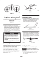
Slope Chart

8

9
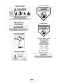
Safety and Instruction Decals
Safety decals and instructions are easily visible to the operator and are located near any
area of potential danger. Replace any decal that is damaged or lost.
Lower Left of Console
(Part No. 98-4387)
On Right Side of Height-of-Cut
Plate
(Part No. 1–653140)
On Left Side of Height-of-Cut
Plate
(Part No. 1–653147)
Below Center Of Console
(Part No. 103–0262)
Top of Console Under Seat
(Part No. 103–0315)
On Control Panel
(Part No. 103–0167)

10
On Top Left Side of Frame
(Part No. 1–633818)
Under Footrest
(Part No. 99-3924)
On Tilt Switch
(Part No. 1–643401)
On Top of Hydraulic
Reservoir
(Part No. 1–523552)
On Frame Near Muffler
(Part No. 65-2690)

11
On Right Side of Mower
(Part No. 661340)
On Left Side of Mower
(Part No. 438480)
(2) On Belt Covers
(Part No. 675360)
On Left Front of Mower
(Part No. 937818)
On Top of Mower in Center
(Part No. 983798)
Under Belt Cover (3)
Under Footrest (1)
(Part No. 98-5954)
On Top Center of Mower
(Part No. 993943)
99–3943
On Deflector
(Part No. 549220)

12
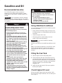
Gasoline and Oil
Recommended Gasoline
Use UNLEADED Regular Gasoline suitable for
automotive use (85 pump octane minimum). Leaded
regular gasoline may be used if unleaded regular is not
available.
Important Never use methanol, gasoline containing
methanol, or gasohol containing more than 10% ethanol
because the fuel system could be damaged. Do not mix oil
with gasoline.
Danger
In certain conditions, gasoline is extremely
flammable and highly explosive. A fire or
explosion from gasoline can burn you and others
and can damage property.
• Fill the fuel tank outdoors, in an open area,
when the engine is cold. Wipe up any gasoline
that spills.
• Do not fill the fuel tank completely full. Add
gasoline to the fuel tank until the level is 1/4 to
1/2 (6 mm to 13 mm) below the bottom of the
filler neck. This empty space in the tank allows
gasoline to expand.
• Never smoke when handling gasoline, and stay
away from an open flame or where gasoline
fumes may be ignited by a spark.
• Store gasoline in an approved container and
keep it out of the reach of children. Never buy
more than a 30-day supply of gasoline.
• Always place gasoline containers on the ground
away from your vehicle before filling.
• Do not fill gasoline containers inside a vehicle
or on a truck or trailer bed because interior
carpets or plastic truck bed liners may insulate
the container and slow the loss of any static
charge.
• When practical, remove gas–powered
equipment from the truck or trailer and refuel
the equipment with its wheels on the ground.
• If this is not possible, then refuel such
equipment on a truck or trailer from a portable
container, rather than from a gasoline
dispenser nozzle.
• If a gasoline dispenser nozzle must be used,
keep the nozzle in contact with the rim of the
fuel tank or container opening at all times until
fueling is complete.
Gasoline is harmful or fatal if swallowed.
Long–term exposure to vapors can cause serious
injury and illness.
• Avoid prolonged breathing of vapors.
• Keep face away from nozzle and gas tank or
conditioner opening.
• Keep gas away from eyes and skin.
Warning
Using Stabilizer/Conditioner
Use a fuel stabilizer/conditioner in the machine to provide
the following benefits:
• Keeps gasoline fresh during storage of 90 days or less.
For longer storage it is recommended that the fuel tank
be drained.
• Cleans the engine while it runs
• Eliminates gum-like varnish buildup in the fuel
system, which causes hard starting
Important Do not use fuel additives containing
methanol or ethanol.
Add the correct amount of gas stabilizer/conditioner to the
gas.
Note: A fuel stabilizer/conditioner is most effective when
mixed with fresh gasoline. To minimize the chance of
varnish deposits in the fuel system, use fuel stabilizer at
all times.
Filling the Fuel Tank
1. Shut the engine off and set the parking brake.
2. Clean around each fuel tank cap and remove the cap.
Add unleaded regular gasoline to both fuel tanks, until
the level is 1/4 to 1/2 inch (6 mm to 13 mm) below the
bottom of the filler neck. This space in the tank allows
gasoline to expand. Do not fill the fuel tanks
completely full.
3. Install fuel tank caps securely. Wipe up any gasoline
that may have spilled.
Check Engine Oil Level
Before you start the engine and use the machine, check
the oil level in the engine crankcase; refer to Checking Oil
Level, page 30.

13
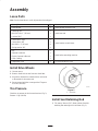
Assembly
Loose Parts
Note: Use the chart below to verify all parts have been shipped.
Description Qty. Use
Rear Wheels 2 Install wheels to traction unit
Retaining rod
Bolt 5/16-18 x 1″ (26 mm)
Locknut 5/16″
1
1
1
Install seat rod
Control lever–right
Control lever–left
Bolt 3/8-1 x 1″ (26 mm)
Spring washer 3/8″
1
1
4
4
Install motion control levers
Key
Operator’s Manual
Engine Operator’s Manual
Parts Catalog
2
1
1
1
Read before operating machine
Registration card 1 Fill out and return to Toro
Install Drive Wheels
1. Uncrate mower.
2. Remove wheel bolts or nuts from rear wheel hubs.
3. Align holes. Mount drive wheels with the valve stem
to the outside of the traction unit.
4. Secure using wheel bolts or nuts provided. Torque to
95 ft-lbs (128 NM).
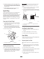
Tire Pressure
Check the air pressure in the front and rear tires (Fig. 2).
Pressure: 13 psi (90 kPa)
1
m–1872
Figure 2
1. Valve stem
Install Seat Retaining Rod
1. Tilt seat up. Remove 5/16″ (8mm) locknut from bolt
attaching seat retaining rod to seat frame (Fig. 3).

14
2. Remove retaining rod from seat and insert the “L”
shaped end of the rod into the hole directly above the
left–side hydraulic pump (Fig. 3).
3. Place the seat retaining rod to the outside of the
mounting tab of the seat frame and secure with
5/16-18 x 1″ (26 mm) bolt and 5/16″ (8mm) locknut
(Fig. 3).
4. Tighten until snug, then loosen so the rod pivots freely.
3
1
m–3750
2
Figure 3
1. L end of retaining rod
2. Locknut 5/16″
3. Bolt 5/16-18 x 1″ (26 mm)
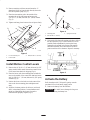
Install Motion Control Levers
1. Remove the (4) 3/8-16 x 1″ (26 mm) bolts and (4) 3/8″
spring washers which attach the motion control levers
to the control arm shafts for shipping (Fig. 4).
2. Place the levers (with the mounting plate towards the
rear) on the outside of the control arm shaft and secure
with (4) 3/8-16 x 1″ (26 mm) bolts and (4) 3/8″ spring
washers (Fig. 4).
3. Position the lever so the bolts are in the center of the
slots on the lever mounting plate and tighten until
snug.
4. Align the front\rear position of the levers, with each
other, in the neutral position. Loosen hardware and
adjust by sliding/tilting the lever(s) forward or
backward until properly aligned (Fig. 4).
m–3751
1
2
3
Figure 4
1. Mounting plate
2. Bolt 3/8-18 x 1″ (26 mm)
3. Spring washer 3/8″
5. If the ends of the levers hit against each other, while in
the drive position (Fig 5) (levers rotated in as far as
possible) make adjustments by moving the levers
outwards to the neutral lock position and carefully
bend them outward. Move them back to the drive
position and check for clearance. Repeat if necessary.
Figure 5
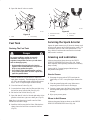
Activate the Battery
Bulk electrolyte with 1.260 specific gravity must be
purchased from a local battery supply outlet.
1. Remove the battery from the machine.
Important Be careful not to damage the long vent
tube when removing the battery box.

15
Danger
Battery electrolyte contains sulfuric acid which is
a deadly poison and causes severe burns.
• Do not drink electrolyte and avoid contact with
skin, eyes or clothing. Wear safety glasses to
shield your eyes and robber gloves to protect
your hands.
• Fill the battery where clean water is always
available for flushing the skin.
• Follow all instructions and comply with all
safety messages on the electrolyte container.
2. Place battery on a level surface.
3. Remove filler caps from the battery. Slowly pour
electrolyte into each cell until the electrolyte level is
up to the lower part of the tube (Fig. 6).
1
2
3
m–1262
Figure 6
1. Filler caps
2. Electrolyte
3. Lower part of the tube
4. Leave the covers off and connect a 3 to 4 amp battery
charger to the battery posts (Fig. 7). Charge the battery
at a rate of 4 amperes or less for 4 hours (12 volts).
4
1
2
3
m–1254
Figure 7
1. Positive post
2. Negative post
3. Charger red (+) wire
4. Charger black (–) wire
Charging battery produces gasses that can
explode and cause serious injury.
• Keep cigarettes, sparks and flames away from
battery.
• Make sure the ignition switch is off.
• Ventilate when charging or using battery in an
enclosed space.
Warning
5. When the battery is fully charged, disconnect the
charger from the electrical outlet then from the
negative and positive battery posts (Fig. 7).
6. Slowly pour electrolyte into each cell until the level is
once again up to the “UPPER” line on the battery case
(Fig. 6) and install covers.
7. Wash off any spilled acid with water. Dry off the
battery.
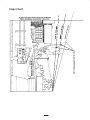
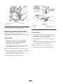
Install Battery
1. Position battery in tray with terminal posts toward the
engine (Fig. 8).
2. First, install the positive (red) battery cable to positive
(+) battery terminal.
3. Then install negative battery cable and ground wire to
the negative (–) battery terminal.
4. Secure cables with (2) 1/4 x 3/4″ (19 mm) bolts 1/4″
washers and 1/4″ locknuts (Fig. 8).

16
5. Slide the red terminal boot onto the positive (red)
battery post.
6. Secure battery with J-bolts, hold down clamp and (2)
1/4″ washers and (2) 1/4″ wing nuts (Fig. 8).
7. Position drain tube away from belts and other parts to
prevent corrosion.
1
m–3752
9 5
2
6
7
10
4
3
8
11
7
12
Figure 8
1. Battery
2. Terminal boot
3. Positive battery cable
4. Negative battery cable
5. Ground wire
6. Bolt 1/4-20 x 3/4″ (19 mm)
7. Washer 1/4″
8. Locknut 1/4″
9. Battery clamp
10. J-bolts
11. Wing nut 1/4″
12. Drain tube
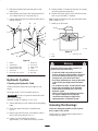
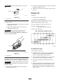
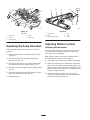
Hydraulic System
Checking the Hydraulic Fluid
Check the hydraulic fluid level before engine is first
started.
Fluid Type: Mobil 1 15W-50 synthetic motor oil.
Important Use only oil specified. Other fluids could
cause system damage.
Hydraulic System Oil Capacity: 2.1 qt. (2.0 l)
1. Position machine on a level surface and set the parking
brake.
2. Clean area around filler neck of hydraulic tank
(Fig. 9).
3. Remove cap from filler neck. Look inside to check if
there is fluid in the reservoir (Fig. 9).
4. If there is no fluid, add fluid to reservoir
approximately a 1/4″ (6mm) below the top of baffle.
5. Run the machine 15 minutes to allow any air to purge
out of the system and warm fluid.
6. Recheck level while fluid is warm. Add fluid to raise
level to top of the baffle, if required.
Note: Fluid level should be to the top of the baffle when
fluid is warm (Fig. 9).
7. Install cap on filler neck.
2
1
3
M-4280
Figure 9
1. Cap
2. Baffle
3. Fluid level—full
Hydraulic fluid escaping under pressure can
penetrate skin and cause injury.
• If hydraulic fluid is injected into the skin it
must be surgically removed within a few hours
by a doctor familiar with this type of injury.
Gangrene may result if this is not done.
• Keep body and hands away from pin hole leaks
or nozzles that eject high pressure hydraulic
fluid.
• Use cardboard or paper to find hydraulic leaks.
• Safely relieve all pressure in the hydraulic
system before performing any work on the
hydraulic system.
• Make sure all hydraulic fluid hoses and lines
are in good condition and all hydraulic
connections and fittings are tight before
applying pressure to hydraulic system.
Warning
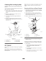
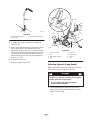
Greasing the Bearings
Make sure cutting unit spindles are full of grease
before engine is first started.
Grease with No. 2 general purpose lithium base or
molybdenum base grease.

17
1. Grease the fittings on the three spindle bearings.
Grease until it comes out lower seals (Fig. 10).
1
M-4159
Figure 10
1. Spindles
Check the Leveling of Mower
Deck
Check the level of the deck before machine is first put
into use.
Refer to Mower Leveling and Compression Spring
Adjustment in the Maintenance section on page 37.
Check Side Discharge Chute
Remove plastic tie holding side discharge chute up and
lower into place.
Check Engine Oil Level
Before you start the engine and use the machine, check
the oil level in the engine crankcase; refer to Checking Oil
Level, page 30.
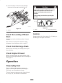
Operation
Think Safety First
Please carefully read all the safety instructions on
pages 3–9. Knowing this information could help you,
your family, pets or bystanders avoid injury.
The use of protective equipment, such as but not limited
to, for eyes, ears, feet and head is recommended.
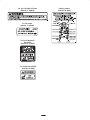
This machine produces sound levels in excess of
85dBA at the operator’s ear and can cause
hearing loss through extended periods of
exposure.
Wear hearing protection when operating this
machine.
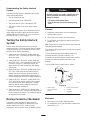
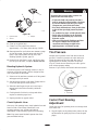
Caution
1
2
Figure 11
1. Caution 2. Wear hearing protection
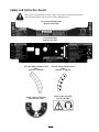
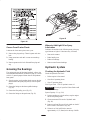
Controls
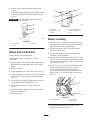
Become familiar with all the controls (Fig. 12) before you
start the engine and operate the machine.

18
7
m–4200
10
2
5
8
49
2
3
8
6
1
Figure 12
1. Ignition switch
2. Motion control lever
3. Parking brake lever
4. Throttle
5. Choke
6. Power take off (PTO)
7. Height-of-Cut lever
8. Fuel cap
9. Hourmeter
10. Fuel shut-off valve
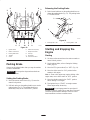
Parking Brake
Always set the parking brake when you stop the machine
or leave it unattended.
Important Do not park on slopes unless wheels are
chocked or blocked.
Setting the Parking Brake
1. Move the motion control levers (Fig. 12) out to the
neutral lock position.
2. Pull back and up on the parking brake lever to set the
parking brake (Fig. 13). The parking brake lever
should stay firmly in the “ENGAGED” position.
Releasing the Parking Brake
1. Push forward and down on the parking brake lever to
release the parking brake (Fig. 13). The parking brake
is “DISENGAGED”.
1
2
m–4121
Figure 13
1. Parking brake—ON 2. Parking brake—OFF
Starting and Stopping the
Engine
Starting
1. Sit down on the seat and move the motion controls to
neutral locked position.
2. Set the parking brake; refer to Setting the Parking
Brake, page 18.
3. Move the PTO (power take off) to “OFF” (Fig. 14).
4. Move the choke control to “ON” position before
starting a cold engine.
Note: A warm or hot engine may require choking. After
engine starts, move choke control to “OFF” position.
5. Move the throttle control to the “FAST” position
before starting a cold engine.
6. Turn ignition key to “START” to energize starter.
When engine starts, release key.
Important Do not engage starter for more than 10
seconds at a time. If engine fails to start allow 30 second
cool-down period between attempts. Failure to follow
these instructions can burn out starter motor.

19
7. After the engine starts, move the choke to “OFF”
(Fig. 15). If the engine stalls or hesitates, move the
choke back to “ON” for a few seconds. Then move the
throttle lever to desired setting. Repeat this as
required.
Figure 14
1. PTO—On
2. PTO—Off
Figure 15
1. Choke—On
2. Choke—Off
1
m–2719
2
1
m–4201
2
Figure 16
1. Fast
2. Slow
Figure 17
1. Off
2. Run
3. Start
2
1
m–2720
1
2
3
m–4268
Stopping
1. Move the throttle lever to “SLOW” (Fig. 16).
2. Move the PTO (power take off) to “OFF” (Fig. 14).
3. Turn the ignition key to “OFF” (Fig. 17).
Note: If the engine has been working hard or is hot, let it
idle for a minute before turning the ignition key “OFF.”
This helps cool the engine before it is stopped. In an
emergency, the engine may be stopped by turning the
ignition key to “OFF.”
4. Pull wire off spark plug(s) to prevent possibility of
someone accidentally starting the machine before
transporting or storing machine.
5. Close fuel shut off valve, on front panel before
transporting or storing machine.
Important Make sure fuel shut off valve is closed
before transporting or storing machine, as fuel leakage
may occur.
Operating the Power Take Off
(PTO)
The power take off (PTO) switch engages and disengages
power to the electric clutch.
Engaging the PTO
1. Release pressure on the traction control levers and
place in neutral.
2. Place throttle to the fast position.
3. Pull out on the power take off (PTO) switch to engage
(Fig. 18).
1
2
m–4201
Figure 18
1. PTO—Off 2. PTO—On
Disengaging the PTO
1. To disengage push the PTO switch to the “OFF”
position (Fig. 18).
The Safety Interlock System
If safety interlock switches are disconnected or
damaged the machine could operate unexpectedly
causing personal injury.
• Do not tamper with the interlock switches.
• Check the operation of the interlock switches
daily and replace any damaged switches before
operating the machine.
Caution

20
Understanding the Safety Interlock
System
The safety interlock system is designed to prevent the
engine from starting unless:
• You are sitting on the seat
• The parking brake is on “ENGAGED”
• The power take off (PTO) is disengaged “OFF”
• The motion control levers are in neutral locked
position
The safety interlock system also is designed to stop the
engine when the traction controls are moved with the
parking brake on “ENGAGED” or if you rise from the
seat when the PTO is “ON” engaged.
Testing the Safety Interlock
System
Test the safety interlock system before you use the
machine each time. If the safety system does not operate
as described below, have an Authorized Service Dealer
repair the safety system immediately.
1. Sitting on the seat, “ENGAGE” parking brake and
move PTO “ON”. Try starting the engine; the engine
should not crank.
2. Sitting on the seat, “ENGAGE” parking brake and
move PTO “OFF”. Move either motion control lever
(forward or reverse). Try starting the engine; the
engine should not crank. Repeat with other motion
control lever.
3. Sitting on the seat, “ENGAGE” parking brake, move
PTO “OFF” and lock the motion control levers in
neutral. Now start the engine. While the engine is
running, release the parking brake, engage the PTO
and rise slightly from the seat; the engine should stop.
4. Sitting on the seat, “ENGAGE” parking brake, PTO
“OFF” and lock the motion control levers in neutral.
Now start the engine. While the engine is running,
center the motion controls and move (forward or
reverse); the engine should stop.
5. Sitting on the seat, “DISENGAGE” parking brake,
move PTO switch “OFF” and move the motion control
levers to neutral lock position. Try starting the engine;
the engine should not crank.
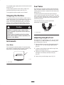
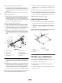
Driving Forward or Backward
The throttle control regulates the engine speed as
measured in rpm (revolutions per minute). Place the
throttle control in the “FAST” position for best
performance. Always operate in the full throttle position.
Machine can spin very rapidly. Operator may lose
control of machine and cause personal injury or
damage to machine.
• Use caution when making turns.
• Slow the machine down before making sharp
turns.
Caution
Forward
1. Release the parking brake; refer to Releasing the
Parking Brake, page 18.
2. Move levers to the center, un-locked position.
3. To go forward, slowly push the motion control levers
forward (Fig. 19).
Note: Engine will kill if traction control levers are moved
with parking brake engaged.
To go straight, apply equal pressure to both motion control
levers (Fig. 19).
To turn, release pressure on the motion control lever
toward the direction you want to turn (Fig. 19).
The farther you move the traction control levers in either
direction, the faster the machine will move in that
direction.
To stop pull the motion control levers to neutral.
4
m–2715
3
1
2
Figure 19
1. Motion control
lever—neutral lock
position
2. Center unlock position
3. Forward
4. Backward
Backward
1. Move levers to the center, unlocked position.
2. To go backward, slowly pull the motion control levers
rearward (Fig. 19).
Page is loading ...
Page is loading ...
Page is loading ...
Page is loading ...
Page is loading ...
Page is loading ...
Page is loading ...
Page is loading ...
Page is loading ...
Page is loading ...
Page is loading ...
Page is loading ...
Page is loading ...
Page is loading ...
Page is loading ...
Page is loading ...
Page is loading ...
Page is loading ...
Page is loading ...
Page is loading ...
Page is loading ...
Page is loading ...
Page is loading ...
Page is loading ...
Page is loading ...
Page is loading ...
Page is loading ...
Page is loading ...
Page is loading ...
Page is loading ...
Page is loading ...
Page is loading ...
-
 1
1
-
 2
2
-
 3
3
-
 4
4
-
 5
5
-
 6
6
-
 7
7
-
 8
8
-
 9
9
-
 10
10
-
 11
11
-
 12
12
-
 13
13
-
 14
14
-
 15
15
-
 16
16
-
 17
17
-
 18
18
-
 19
19
-
 20
20
-
 21
21
-
 22
22
-
 23
23
-
 24
24
-
 25
25
-
 26
26
-
 27
27
-
 28
28
-
 29
29
-
 30
30
-
 31
31
-
 32
32
-
 33
33
-
 34
34
-
 35
35
-
 36
36
-
 37
37
-
 38
38
-
 39
39
-
 40
40
-
 41
41
-
 42
42
-
 43
43
-
 44
44
-
 45
45
-
 46
46
-
 47
47
-
 48
48
-
 49
49
-
 50
50
-
 51
51
-
 52
52


Toro Z153 Z Master, With 52" SFS Side Discharge Mower User manual
- Category
- Lawnmowers
- Type
- User manual
Ask a question and I''ll find the answer in the document
Finding information in a document is now easier with AI
Related papers
-
Toro Z149 Z Master, With 52" SFS Side Discharge Mower User manual
-
Toro Z153 Z Master, With 52" SFS Side Discharge Mower User manual
-
Toro Z150 Z Master, With 52" SFS Side Discharge Mower User manual
-
-
-
-
-
-
-
Toro Z287L Z Master, With 62" SFS Side Discharge Mower User manual
Other documents
-
Husqvarna 968999204 / iZ4218KAA User manual
-
-
-
Stiga VILLA 102M Instructions For Use Manual
-
National All Day Battery Ride-On 7700 User manual
-
 Airflo AFW900 User manual
-
-
 SupaSwift 20`` Cylinder Mower 420ACM User manual
-
 SupaSwift 17`` Cylinder Mower 417ACM User manual
-
Lawn-Boy Silver Series 10360 User manual


