Page is loading ...

LaZerWeld Plate Heat Exchangers
THIS MANUAL CONTAINS RIGGING, ASSEMBLY, START-UP,
AND MAINTENANCE INSTRUCTIONS. READ THOROUGHLY
BEFORE BEGINNING INSTALLATION. FAILURE TO FOLLOW THESE
INSTRUCTIONS COULD RESULT IN DAMAGE OR IMPROPER
OPERATION OF THE UNIT.
Form 190.200-IOM (MAR 2018)
INSTALLATION - OPERATION - MAINTENANCE
File: SERVICE MANUAL - Section 190
Replaces: 190.200-IOM (MAY 2017)
Dist: 3, 3a, 3b, 3c
Please check www.johnsoncontrols.com/frick for the latest version of this publication.

190.200-IOM (MAR 2018)
Page 2
LAZERWELD HEAT EXCHANGER
INSTALLATION - OPERATION - MAINTENANCE
Indicates an imminently hazardous situation which, if not avoided, will result in death or serious
injury.
Indicates a potentially hazardous situation or practice which, if not avoided, will result in death or
serious injury.
SAFETY PRECAUTION DEFINITIONS
Indicates a potentially hazardous situation or practice which, if not avoided, will result in damage
to equipment and/or minor injury.
Indicates an operating procedure, practice, etc., or portion thereof which is essential to highlight.
DANGER
WARNING
CAUTION
NOTICE
Read this manual carefully before unpacking the equipment. Always observe the Safety Notes designated by the Warning
symbol listed throughout this manual.
Contents
GENERAL INFORMATION
Preface ...............................................................................3
How to contact Johnson Controls ...................................3
Warranty Information .........................................................3
New Semi-Welded Plate Heat Exchangers ......................3
Operating Principle ........................................................... 4
Standard design ............................................................. 4
Frame ............................................................................. 4
LaZerWeld – welded plate pairs ..................................... 4
In-line Filters ...................................................................5
General Safety Precautions ................................................5
Receiving of equipment......................................................5
Receiving check...............................................................5
Drawing Documentation ..................................................6
Assembly Details .............................................................6
General Arrangement Details ..........................................6
PHE Plate Arrangement Details .......................................6
Nameplate .......................................................................6
Handling .............................................................................7
Lifting ..............................................................................7
INSTALLATION
Foundation ......................................................................8
Space requirements ........................................................8
Connections ....................................................................8
Storage ..............................................................................8
Short Term Storage (less than 6 months) ........................8
Long Term Storage (more than 6 months) .......................8
OPERATION
Start-up and operation ......................................................9
Start-up ...........................................................................9
Operation ........................................................................9
Operational DOs And DON’Ts ..........................................9
Corrosion resistance ........................................................ 9
Shutting down .................................................................9
MAINTENANCE
Disassembly ....................................................................10
Cleaning ........................................................................10
Manual Cleaning ............................................................10
Cleaning-In-Place .......................................................... 11
Example of CIP Cleaning: .............................................. 11
Determination Of Correct CIP System ...........................11
Commissioning & Troubleshooting Do’s And Don’ts ......12
Reassembly ......................................................................12
LZW Return-To-Duty Testing Requiremnet Notice .......12
Maintenance & Inspection .............................................14
Maintenance Of In-line Filter ........................................15
Clean The In-line Filter In This Sequence: ..................... 15
Spare Parts – Identication And Ordering
Identication Of Spare Parts ..................................... 15
Storage of LZW Plate Heat Exchanger Gaskets .............15
Troubleshooting ...............................................................16
FACTORY ASSISTED FIELD SERVICE FORM
LZW Site Service Preparation Checklist: ..........................17
Field Testing of the Plate Heat Exchanger ........................18
NOTICE
The LZW Semi-Welded plate heat exchanger is an ASME pressure containing device.
The repair and refurbishment of pressure vessels is covered by the National Board of Pressure Vessel Inspectors
National Board Inspection Code (NBIC). Most Authorities Having Jurisdiction (AHJ) do not consider direct replacement
of plates and gaskets in a plate heat exchanger a “repair” and do not require inspection or application of the “R” stamp.
However, the AHJ where the unit is to be operated should be consulted for their interpretation of NBIC requirements.
There are also occasions where the customer or their insurance company demands the application of the “R” stamp,
even when the AHJ does not.

190.200-IOM (MAR 2018)
Page 3
LAZERWELD HEAT EXCHANGER
INSTALLATION - OPERATION - MAINTENANCE
Important!
In addition to this instruction manual, the following key
documents are included with your LaZerWeld™ plate heat
exchanger. In case of conict between this instruction
manual and the order and product documents, the order and
product specic documents take precedence.
• LaZerWeld PHE Plate Arrangement Drawing
• LaZerWeld Assembly Drawing which may be integrated
with the plate arrangement drawing
• Other Order-specic documentation
• Supplementary Instruction manuals dealing with specic
topics
Further details can be found in Section: “Receiving equipment”.
How to contact Johnson Controls:
Your nearest ofce is listed on our website: www.johnson-
controls/frick. There, you can also nd information regarding
our Service and Spare Parts offerings.
Thank you for choosing Frick equipment!
General Information
PREFACE
This manual has been prepared to acquaint the owner and
serviceman with the INSTALLATION, OPERATION and MAIN-
TENANCE procedures as recommended by Frick® Industrial
Refrigeration for the LaZerWeld Plate Heat Exchanger.
Proper performance and continued satisfaction with these
units is dependent upon:
CORRECT INSTALLATION
PROPER OPERATION
REGULAR, SYSTEMATIC MAINTENANCE
To ensure correct installation and application, the LZW unit
should be connected to a properly designed and installed
system.
NOTICE
Illustrations of LaZerWeld heat exchangers and
equipment presented in this manual serve as example
illustrations only in support of the instructions. Your
actual equipment may look different.
WARRANTY INFORMATION
New Semi-Welded Plate Heat Exchangers
WARRANTY and LIABILITY: LaZerWeld semi-welded plate
heat exchangers are warranted to be free from defects in
material and workmanship for a period of 12 months from
start of operation or 18 months from date of shipment unless
subject to an extended Warranty Protection Program offered
on the originally purchase date and specically stated in the
original order documents.
Any Warranty Protection is only valid when the LaZerWeld
plate heat exchanger is installed, operated, and maintained
according to the Frick® Industrial Refrigeration service
manual, Form 190.200-IOM. Any deviation from the
operating or service and maintenance instructions provided
in the service manual, at any location, by any individual or
company will void the protection coverage in full.
Buyer’s remedy for Warranty Protection Coverage pertaining
to Frick LaZerWeld heat exchangers shall be limited to the
repair or replacement, based on the opinion and option of
Frick Industrial Refrigeration and SPX Flow, of any product(s)
or part(s) which by examination are disclosed to be defective.
Warranty Protection Coverage does not include: (1) Any
labor; (2) Extraneous materials, such as test gases, etc; (3)
Other charges incurred associated with the removal, repair
or replacement of the defective part(s).
Warranty Protection Coverage shall be void if the equipment
has been subjected to: (1) negligence, abnormal conditions;
(2) abuse, alterations; (3) misuse, damaged due to other
failure(s) within the system; (4) chemicals attack, corrosion,
erosion; (5) excessive or cyclical pressures, vibrations; (6)
accidents, physical damage (in transit or after installation); (7)
misapplication or operation contrary to the manufacturer’s
recommendations
Any claims for defects must be made, promptly, in writing
using Frick form (190.200-FRM), completely specifying the
nature of such defects. Failure to do so shall constitute a
waiver of the claim. Labor associated with claim related
repairs must be performed by an authorized SPX Flow
service technician using OEM parts.
The Buyer must have written authorization, including a
Return Goods Authorization Number (RGA #), for the return
of any defective product(s) or part(s). This RGA # must be
clearly marked on the returned product(s) or part(s). Frick
and/or SPX Flow are not responsible for lost returns. The
freight charges associated with warranty parts and return
goods, both to and from the factory, are the responsibility
of the Buyer.
If the defective part(s) is not returned to Frick Industrial
Refrigeration or SPX Flow as dened on the RGA document
within 30 days from date of shipment of the replacement
part, the customer will be invoiced for the replacement part.
In the event that Frick Industrial Refrigeration fails to make
delivery or repudiate, Buyer’s sole and exclusive remedy shall
be repayment of that part of the purchase price therefore
paid by Buyer. In no event shall Frick Industrial Refrigeration
or SPX Flow be liable for damages in an amount exceeding
the amount of the purchase price paid for the product or part
concerning which a claim for damages arises. (Any right of
Buyer to consequential or incidental damages is excluded.
Any action for breach of warranty or otherwise for breach
of any agreement arising from our acceptance of an order
placed by Buyer, whether or not based on our quotation,
must be commenced within 12 months or applicable Frick
Warranty period after cause of action arises.) Any action
shall thereafter be barred.
*The full text of this warranty is available in document 020.160-W.

190.200-IOM (MAR 2018)
Page 4
LAZERWELD HEAT EXCHANGER
INSTALLATION - OPERATION - MAINTENANCE
OPERATING PRINCIPLE
Standard design
The plate heat exchanger consists of a number of thin
corrugated metal plates.
The plate corrugations form ow channels for the heat
exchanging uids and provide strength to the compressed
plate pack.
The plates contain ports for uid inlets, outlets and
interconnect passages as required.
Gaskets are attached to the plates, forming a seal between
the heat exchanging uids and the surroundings.
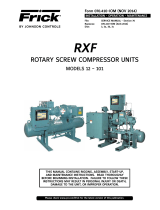
In the example shown here in Figure 1, the cold uid (blue)
enters at the bottom and the hot uid (red) at the top.
Figure 1 - Fluid Movement
Frame
The plates are clamped together to a predetermined
dimension by the tie bars between two thick metal slabs:
a stationary slab (head) and a moveable slab (follower).
Connections for the uid inlets and outlets can be made on
either slab. The plates are hung on the top bar and guided by
the bottom bar. An end column supports the top and bottom
bar ends. See Figure 2.
Figure 2 - Plate Clamping Design
Figure 3 - Welded Plate Pair System
LaZerWeld – welded plate pairs
LaZerWeld plate pair is a right- and left-hand plate laser
welded together to form a pair. This welded plate pair
system is particularly suitable for use with refrigerants such

190.200-IOM (MAR 2018)
Page 5
LAZERWELD HEAT EXCHANGER
INSTALLATION - OPERATION - MAINTENANCE
as ammonia and Freon or with other aggressive liquids that
could otherwise attack the gaskets in a conventional heat
exchanger plate. See Figure 3.
When the welded pairs are installed in a frame, each pair is
sealed by elastomeric seals.
NOTICE
A LaZerWeld plate pair cannot be separated for
inspection and cleaning. It is, therefore, important to
prevent fouling and clogging of the welded passage.
If fouling in the welded passage cannot be prevented, then
cleaning must be done by circulating a cleaning solution. It is
recommended that you contact a supplier of cleaning agents
for advice.
WARNING
The two sides of LaZerWeld PHE may have different
pressure and uid compatibility and therefore care must
be exercised in connecting the uids correctly.
WARNING
LaZerWeld PHE is not suitable for hygienic duties where
organic fouling is expected, for example, dairy products.
Figure 4 - LaZerWeld In-Line Filter
In-line Filters
For industrial applications involving bers or particles
which might foul the heat exchanger plates or block the
heat exchanger passages, a LaZerWeld in-line lter is
recommended. See Figure 4.
The LaZerWeld in-line lter is inserted in the uid inlet port
of the heat exchanger through an opening in the follower
and closed with a full-faced gasket blind cover. The in-line
lter mesh size is 2.5 mm (0.1 inch) for most models. A mesh
size of 2.0mm is required for LZW 650 and 1800 models, and
is recommended for LZW 115 and 360 models.
Where an in-line lter is purchased for an existing LaZerWeld
PHE, please check whether the follower is prepared for the
installation of an in-line lter. A replacement follower or
machining may become necessary.
LaZerWeld Plate Heat Exchangers are designed and
manufactured with due consideration and care for generally
accepted safety standards. As with any mechanical device,
the proper and safe performance of the equipment depends
on safe handling, operation, and maintenance.
GENERAL SAFETY PRECAUTIONS
WARNING
The following general safety precautions must be
followed in order to avoid personal injury or equipment
damage:
1. Always observe any applicable local and national safety
codes.
2. Always use appropriate protective gear, such as safety
gloves and safety shoes when touching and handling the
equipment.
3. Follow proper lifting procedures while handling the
equipment.
4. Never expose the equipment to heat, aggressive
chemicals or mechanical impact that can damage the
equipment.
5. Only qualied persons should handle and operate the
equipment.
RECEIVING OF EQUIPMENT
Receiving check
LaZerWeld Plate Heat Exchangers may be shipped fully
assembled and skid mounted. The PHE is normally mounted
on pallets and wrapped in protective plastic. Other wrappings
could be in open box or seaworthy packaging.
Prior to unpacking, check the packing for any defects and
the equipment for possible damage that might have occurred
during transportation. Any damage as a result of shipping
must be reported immediately. See Figure 5.

190.200-IOM (MAR 2018)
Page 6
LAZERWELD HEAT EXCHANGER
INSTALLATION - OPERATION - MAINTENANCE
Figure 5 - Check Before Unpacking
Figure 6 - Check the Equipment
Check the equipment according to the documentation
provided with the shipment. Any deviations must be reported
immediately. See Figure 6.
Drawing Documentation
The ofcial drawing that is included with the equipment:
including the following detailed elements:
• Assembly information (Figure 7)
• General arrangement details
• PHE Plate Arrangement information including parts listing
Figure 7 - Assembly Drawing
Assembly Details
The drawing provides information concerning overall
dimensions, bolt-down positions and a connection diagram
showing where external piping will be connected.
General Arrangement Details
This general arrangement detail provides the same
information, as the assembly detail plus additional customer
specied information. See Figure 8.
Figure 8 - General Arrangement Details
PHE Plate Arrangement Details
The plate heat exchanger is designed to perform a duty (or
duties) by arranging the number and type of plates required
in a specic sequence. This arrangement is represented
schematically by the plate diagram shown on the arrangement
drawing (Figure 9).
The drawing summarizes the plates and gaskets in the plate
heat exchanger design.
The summary includes plate types, angles, thickness and
material, along with gasket type, material and attachment
method (glued or clip in) and part no.
The assembly detail summarizes compressed plate pack
dimension, total weight and hold-up volume.
Figure 9 - Plate Arrangement Details
Nameplate
Identication of the equipment is printed on the nameplate
(mounted on the head or follower). When contacting Johnson

190.200-IOM (MAR 2018)
Page 7
LAZERWELD HEAT EXCHANGER
INSTALLATION - OPERATION - MAINTENANCE
Controls-Frick for service or spare parts, always refer to the
serial number on the nameplate (Figure 10).
Figure 10 - Nameplate
HANDLING
Lifting
If the plate heat exchanger is packed and transported lying
at on the head, great care must be taken during raising it, to
avoid sliding and impact of bending forces to the equipment
base or feet.
LaZerWeld Plate Heat Exchangers are provided with lifting
lugs or holes (Figure 12) for safe lifting and transportation
of the unpacked equipment. See Figure 11 - using followers!
When lifting an assembled heat exchanger frame, ensure
that the lifting point is above the centre of gravity of the
equipment.
WARNING
The lifting equipment must be in good condition and
should always be used in full compliance with the
specications and limitations given for the equipment.
Always maintain the minimum angle between the lifting
wires in order not to exceed the allowable wire tension.
The angle should not exceed 120° at any time. If the
ceiling height does not allow for safe lifting angle, dollies
or creepers can be used for moving the equipment.
WARNING
Always observe proper procedures for lifting and/
or moving equipment and qualied personnel for the
lifting and moving. Personnel must follow safe rigging
practices.
Indiscriminate use of fork lift trucks may damage the PHE in
critical areas.
See WARNING
concerning lifting
from follower!
Figure 11 - Lifting With Followers
WARNING
Lifting from the follower shown above is not acceptable
for some models and plate damage may result. Check
for warning signs on the follower supplied. Use
alternative lifting eyes, for example as shown below,
in those cases.
Figure 12 - Lifting Using Lifting Eyes

190.200-IOM (MAR 2018)
Page 8
LAZERWELD HEAT EXCHANGER
INSTALLATION
Installation
Foundation
The LaZerWeld Plate Heat Exchanger should be placed on
a solid foundation oor. If the unit is provided with feet,
the dimensions and placement of these are stated on the
assembly drawing.
Space requirements
Ensure that there is sufcient space around the plate heat
exchanger to separate the plate pack and to remove or insert
plates. The amount of free space required is stated on the
assembly drawing. See Figure 13.
Figure 13 - Space Allowance for Servicing
WARNING
Ensure sufcient space around the plate heat exchanger.
Connections
If the plate heat exchanger has liquid connections on the
follower, it is important that the compressed dimension is
checked against the drawing before the pipes are connected.
For easy disassembly and reassembly of the plate heat
exchanger, a pipe elbow should be used at all follower
connections.
The plate heat exchanger connections on the follower and
connector grids have little strength against pipe work or
nozzle loads. Such loads can arise for example from thermal
expansion. Proper care must be taken to avoid transfer of
such pipe forces and moments to the PHE.
STORAGE
Short Term Storage (less than 6 months)
The plate heat exchanger must be stored in a cool and
dry environment away from sunlight. It must be protected
from water and debris with a waterproof cover, while also
allowing for air circulation.
WARNING
Ozone-producing equipment, salt air and other corrosive
atmospheres must be avoided at all times.
Long Term Storage (more than 6 months)
The heat exchanger must be stored in a cool and dry
environment away from sunlight. It must be protected by
a waterproof cover against water and debris, however still
allowing for air circulation.
All connections must be closed to prevent water or debris to
enter the heat exchanger. Factory installed plugs or covers
may be used.

190.200-IOM (MAR 2018)
Page 9
LAZERWELD HEAT EXCHANGER
OPERATION
Operation
START-UP AND OPERATION
Start-up
WARNING
Start-up of the plate heat exchanger must be undertaken
slowly and smoothly to avoid any pressure shocks/
water hammering which might damage the equipment
or cause leakage.
Do not allow pressure changes of more than 10 bar (150
psi) per minute. Temperature changes may be harder
to control but ideally should be limited to less than 10
deg C (20 deg F) per minute. Cyclic hydraulic or thermal
conditions can cause serious damage to the PHE.
If the plate heat exchanger is provided with shutoff
valves at the inlets, these should be closed prior to
start-up and then opened slowly after pump start-up
Operation
The LaZerWeld plate heat exchangers are designed
according to predened temperatures, allowable pressure
drops, design pressures and uid compositions.
WARNING
Exceeding the design temperatures and pressures can
be harmful to the equipment and personnel, and must
be avoided.
Deviations from the designated uid composition may
cause corrosion of the plates and damage on the gaskets,
even if the deviations occur over relatively short time
periods.
Operational DOs And DON’Ts
1. Never charge liquid refrigerant into an evacuated heat
exchanger. This can cause the gaskets to chill to a point
where their elastic sealing properties are lost.
Generally, Paraprene (Chloroprene) gaskets remain exible
above -27°C / -13°F. Nitrile gaskets are exible above
-15°C / +5°F including Parator (Hydrogenated Nitrile). Low
Temperature Nitrile is exible above -45°C / -49°F. EPDM
gaskets are exible above -35°C / -31°F.
NOTICE
It is important to nd a way of charging the PHE with
gas rather than liquid.
2. Never freeze the gaskets on pump down.
3. Do not allow the process medium to freeze. Freezing
causes expansion and can lead to process side leaks and
gasket damage.
4. Do not allow any liquid refrigerant to remain in the heat
exchanger when the process channels will be cleaned-in-
place. Pump down to a procedure similar to the one attached.
There must be a fool proof method to ensure that CIP cannot
be activated while the PHE is charged with refrigerant.
Corrosion resistance
Before entering into operation you should assure that the
media do not exceed the corrosion resistance level of
the materials chosen for your Plate Heat Exchanger. Even
unprocessed water may contain such high level of corrosive
content (e.g. chloride content) that it may attack the plate
surface. A high temperature may accelerate the corrosion
process. Visit www.johnsonsontrols.com for more info.
Shutting down
The heat exchanger must be shut down slowly and allowed
to cool naturally to ambient temperature. Inlet valves, if
used, should be closed before closing the outlet valves.
If steam is used as a heating medium, it must be shut off rst.
In chilling duties, the cooling liquid must be shut down rst
to avoid freezing of the product.
WARNING
Sudden changes in the operating pressures and
temperatures should be avoided. Shock cooling of the
heat exchanger may cause leakages, due to sudden
contraction of the sealing gaskets.
All liquids should be drained from the heat exchanger after
shut down to prevent precipitation of products or scale build-
up. In the case of corrosive media, it may also be necessary
to ush with clean, noncorrosive water.

190.200-IOM (MAR 2018)
Page 10
LAZERWELD HEAT EXCHANGER
MAINTENANCE
Maintenance
WARNING
Never open the LaZerWeld plate heat exchanger until
the unit has cooled below 40°C (105°F).
Never open an LaZerWeld heat exchanger, which is
under pressure from any source.
Never open an LaZerWeld plate heat exchanger with
piping connected to the follower or connector grids.
DISASSEMBLY
Close the shutoff valves and drain the heat exchanger as
much as possible.
Disconnect any pipes connected to the follower.
Loosening and tightening of tie bars in the LaZerWeld
Medium and Small range plate heat exchangers can normally
be accomplished with ratchet wrenches/ spanners. Larger
units require hydraulic equipment or pneumatic/ electric
torque converters.
Measure and record the compressed dimension of the plate
pack before loosening the tie bars.
WARNING
As for any bolted vessel, bolts must not be slackened or
tightened indiscriminately, but approaching a cylinder
head sequence, balancing the opening on the right and
left throughout the process.
In the process below, dimension X is the initial compressed
dimension of the plate pack.
Loosen all tie bars in 3 mm increments to “X + 5%”, and
then remove only the 2 top and the 2 bottom tie bars in the
positions shown in the picture.
Loosen rest off the tie bars in increments of up to 6 mm to
“X + 10%”.
Top
Right
Side
Left
Side
14
2
3
Top
Bottom
Right
Side
Left
Side
14
2
6
3
5
Figure 14 - Large Units Figure 15 - Small Units
Order For Removing Tie Bars
For large or tall units ( where the distance between tie bars
labelled 1 and 3, exceeds 1200 mm, 4 ft), remove all tie bars
except 1 to 6. Loosen tie bars 1 to 6, moving in that order,
in increments of max. 25 mm until all tie bars become loose.
See Figure 14.
For smaller units, (distance between bars 1 and 3 is less than
1200 mm, 4 ft) remove all tie bars except 1 to 4. Loosen tie
bars 1 to 4, moving in that order, in increments of max. 25
mm until all tie bars become loose. See Figure 15.
When using hydraulic tightening units, ensure that each tie
bar is loosened equally during opening.
When the plate pack is fully released and the tie bars
removed, the heat exchanger can be opened by pushing the
follower back against the end support.
WARNING
For large units, block the follower into position, for
example by tying it to the end support, to provide extra
safety against accidental rolling of the follower during
maintenance.
Separate the plate pack carefully to avoid damaging the
gaskets or the plates.
CAUTION
Always wear protective gloves when handling plates.
Remove the plates by lifting them backwards and then
sideways off the top bar and then sliding out of the frame.
See Figure 16.
Figure 16 - Removal of Plates
Cleaning
The plate heat exchanger can be cleaned without opening
(i.e. cleaning-in-place) and manual cleaning.
Manual Cleaning
Manual cleaning is normally accomplished by washing down the
plates with a soft nonmetal brush, water and a cleaning agent.
See Figure 17.

190.200-IOM (MAR 2018)
Page 11
LAZERWELD HEAT EXCHANGER
MAINTENANCE
Figure 17 - Manual Cleaning Process
CAUTION
Cleaning agents must not be aggressive or corrosive
to the plates or the gaskets. If in doubt, contact the
cleaning agent supplier.
Cleaning agents should always be used according to safety
regulations and as specied by the supplier.
It is recommended to lay the plate on a at surface during
brush cleaning to avoid the risk of bending the plate.
If the heat exchanger is heavily fouled, care must be taken
to remove all debris from the gasket sealing surfaces when
the heat exchanger is reassembled. Any debris will most
likely lead to sealing failures. Do not forget that for glue free
gaskets, gasket sealing surfaces to be checked are at the top
as well as bottom surface of the gasket.
In many cases, fouling may be far too tenacious. LZW service
centers around the world may be approached for thorough
cleaning and inspection of the plate pack and regasketing.
Cleaning-In-Place
Cleaning in place (CIP) is accomplished by circulating a
suitable cleaning solution through the plate heat exchanger
instead of opening it.
CIP works best in the reverse direction of normal ow. Good
results are also possible with same direction ow and at
higher velocities than the product ow velocity.
The cleaning solution must be circulated at sufcient velocity
to ush out the product. Higher viscosity products generally
require higher velocity ushing to properly clean.
The cleaning solution must be able to dissolve the fouling on
the plates and great care must be taken to select a proper
cleaning solution that does not damage plates or gaskets.
Example of CIP Cleaning:
1. Drain product residues, cooling and heating media.
2. Rinse with cold or lukewarm water.
3. Circulate warm cleaning uid solution.
4. Rinse with warm water or warm water with softener added.
5. Rinse with cold or lukewarm water.
In simple cases cleaning can also be effected without circula-
tion but by pouring a cleaning uid solution into the system.
After some time of standing, ush the solution with clean water.
If the heat exchanger is to be out of service for a long time,
it is advisable to empty it, separate the plates, and clean
the unit. After cleaning, lightly re-clamp the plate pack and
cover it to protect from dirt and UV light. Please refer to
section 7.0 on Storage.
Determination Of Correct CIP System
The heat exchanger must be opened for inspection at regular
intervals. This is necessary especially during the initial start
up period, until experience has been gained on the effective-
ness of the cleaning regime. With these inspections, it will
gradually be possible to determine circulation times, tem-
peratures, and chemical concentrations with great certainty.
Insufcient cleaning is most often due to:
• Insufcient circulation rate.
• Insufcient cleaning time or temperature.
• Insufcient Concentration of the cleaning agent.
• Excessive periods of operation.
WARNING
Do not use chlorine-containing agents such as
hydrochloric acid (HCI).
Example of an acceptable solution for dairy applications and
AISI 316 plates and NBR gaskets:
• Oils and fats are removed with a water-emulsifying oil
solvent, e.g. BP-System Cleaner.
Organics and greasy coatings are removed with
Sodium hydroxide (NaOH) -max. concentration 2.0%
- max. temperature 85°C (185°F). 2.0% concentration
corresponds to 5.0 litre 30% NaOH per 100 litre water.
• Mineral scale deposits are removed with Nitric acid
(HN03)-max. concentration 0.5% - max. temperature
65°C (150°F). 0.5 % concentration corresponds to 0.58
litre 62% HN03 per 100 litres water.
CAUTION
Excess Nitric acid can seriously damage NBR and other
types of rubber gaskets.
• Nonorganic deposits can be removed by special
LaZerWeld Clean.
• Several alternatives to Nitric acid can be used, e.g.:
Phosphoric acid up to 5% and 85°C.
Recommended Limits for Process Side CIP or Sanitizing*
Chemical Concentration
MAX
Temperature
MAX ∆
Duration
MAX
Caustic Soda ∆1.00% 60°C 2 hrs
Nitric Acid 0.50% 60°C 2 hrs
Phosphoric Acid 5.00% 60°C 2 hrs
Sulphamic Acid
† 0.25% 60°C 1 hr
Hydrogen
Peroxide 1.00% 40°C 1 hr
* Never activate warm or hot CIP unless the refrigerant is
removed.
∆ Do not exceed 60°C ever with caustic soda in the presence
of Paraprene (neoprene) gaskets.
† Note that sulphamic acid solution must be freshly prepared
to avoid a change to sulphuric acid. If in doubt, check
compatibility of gasket material with cleaning chemical.
(Check with cleaning chemical supplier rst.)

190.200-IOM (MAR 2018)
Page 12
LAZERWELD HEAT EXCHANGER
MAINTENANCE
Commissioning & Troubleshooting Do’s And Don’ts
1. Always follow the instruction manual.
2. Check that tie bars are tight. Snug up to approximately
100 lb-ft. This equates to applying approximately a 70
pounds load at the end of an 18" arm wrench.
3. Do not open a heat exchanger for any reason unless the
following issues have been carefully evaluated. (It is only
intended to open these units at planned regasketing).
3.1 Elastomer gaskets may change their mechanical
properties when exposed to refrigerants, lubricants and
operating temperatures. Once a plate heat exchanger
is opened those gaskets may not t properly and seal a
second time. It is prudent to have a fresh set of gaskets
on hand before commencing service work.
3.2 Ensure that dust and debris cannot fall onto gasket
surfaces during opening and closing. Keep gaskets and
grooves clean.
3.3 Before opening the heat exchanger, document the
compressed plate measurement as indicated in Fig. 21
of this manual. If troubleshooting a leak, identify and
document the location of the perceived leak location.
Felt tip markers and pictures are excellent methods of
documentation.
3.4 The use of a sulfur stick is recommended for detecting an
ammonia leak. The burning sulfur will create a plume in
the presence of the leaking ammonia.
3.5 Special attention should be paid at the plate pack
extremities when checking for leaks. In other words,
• Seals between the rst plate pair after the head
• Between the rst plate pair and the second pair
• Between the last plate pair and the follower
• Between the last plate pair and the penultimate pair
• Both sides of the divider plate and neighboring pairs
3.6 With any follower connection leak, look for pipe forces
and moments which might cause follower deection
and leaks. Follower resistance to loads and moments is
limited.
3.7 When reassembling the plate heat exchanger, make sure
that the frame components are free of paint wherever
there is a refrigerant seal. i.e. around the ports in the
head, divider plates and follower. Some refrigerants,
particularly ammonia, degrade paint and can cause leaks.
3.8 If the follower plate has any port connection on it, special
care must be exercised to ensure that the frame port
rings align well with the plate port sealing surface. Use
a suitable technique to check alignment, e.g. engineer’s
blue.
3.9 It is necessary once an LZW heat exchanger has been
opened for service that it is then pressure and vacuum
tested prior to returning it to refrigeration duty. Please
follow the published factory recommendations for eld
testing.
4. Do not use superglue to attach the gaskets to the plates
for any reason. Avoid glue as far as practicable where
refrigerant seals are maintained, i.e. plate and frame port
rings. Some glues have chlorine compounds which can cause
plate cracking.
REASSEMBLY
Wipe the top bar clean with a soft cloth.
Apply suitable grease on the hanging surface where plates
will slide.
When replacing old plates, ensure that the new plates are
reinstalled in the correct sequence and orientation as stated
on the PHE Plate arrangement drawing.
CAUTION
Do not permanently bend or scratch the plates or
damage the gaskets during the installation. Some
plates must be carefully bent to install them.
Push the plates towards the head checking carefully that
they are correctly mounted.
When the plate pack has been correctly assembled, in most
models, plate edges will create a honeycomb (Figure 18). So,
check the edge of the plate pack for unusual patterns before
tightening the PHE.
Figure 18 - Correct Assembly Will Create a Honeycomb
Check the tie bars. Brush clean and grease over the working
lengths.
Once the plate pack has been carefully pushed towards the
xed head and then the follower is pushed against the plate
pack, then tie bar have to be placed in their positions
In the process shown in Figure 21, dimension X is the nal
intended compressed dimension of the plate pack.
NOTICE
It is important that any LZW plate heat exchanger that
has been opened for service be properly tested for
integrity before it is returned to duty. The Frick Service
Bulletin - 190.200-SB Heat Exchanger Field Service -
outlines the necessary steps to assure that the serviced
unit is ready to return to service.
LZW Return-To-Duty Testing Requiremnet Notice

190.200-IOM (MAR 2018)
Page 13
LAZERWELD HEAT EXCHANGER
MAINTENANCE
Top
Right
Side
Left
Side
14
2
3
Top
Bottom
Right
Side
Left
Side
14
2
6
3
5
Figure 19 - Smaller Units Figure 20 - Large Units
Order To Tighten Tie Bars
For Small To Mid-sized Units
(Distance between bars 1 and 3 < 1200 mm)
Compress plate pack in small increments, moving diagonally
from one tie bar to the next. Reach nal dimension X + 10%
by tightening bars 1 to 4 in the order given, in increments of
25 mm or less. Then add all left side and right side bars and
tighten all bars to dimension X+5% in increment of 6 mm or
less. Then add the 2 top and 2 bottom bars and compress in
3 mm increments to X. See Figure 19.
For Large Units
(Distance between bars 1 and 3 >1200 mm)
Compress plate pack in small increments, always moving
diagonally from one tie bar to the next. Reach nal dimension
X + 10% by tightening bars 1 to 6 in the order given, in
increments of 25 mm or less. Then add all left side and right
side bars. Tighten all bars to dimension X+5% in increment
of 6 mm or less. Then add the 2 top and 2 bottom bars and
compress in 3 mm increments to X. See Figure 20.
Figure 21 - Check X Dimension When Tightened
By using hydraulic compression tools 2, 4 or 6 bolts can
be compressed at the same time. The order of bolts and
increments must be the same as above.
It’s important that head and follower are kept parallel during
the compression work.
In this regard, compression must be measured at the top,
middle, and bottom sides. Measurements are to be taken
close to the tie bars. See Figure 21.
WARNING
Always tighten to full plate to plate contact, demonstrated
by sufcient force and within the dimensions permitted.
On the nameplate or the assembly drawing, you will
nd the minimum and maximum compressed dimension
of the plate pack.
In multisection machines, differences in pressures through
the sections can set up a concertina effect where higher
pressure sections open up by a few hundredths of millimetres
per plate and lower pressure sections close down (Figure 22).
Opening up of higher pressure sections can cause leakage of
that section. The robustness of the PHE is also linked with
the percentage division of plate counts in various sections.
Figure 22 - Pressure Differences
CAUTION
To ensure leak free operation in such applications, it
is even more important that the plates contact well
with each other. Well contacting plates are far more
resistant to the concertina effect. Always tighten to full
plate contact.
The concertina effect at minimum compressed dimension is
always very small and therefore the plate pack is more rigid
and robust against leakage.
Irrespective of new or old plates or a mix of new and old
plates, the plates must always be compressed to full contact.
Due to tolerances the full plate contact is attained between
maximum and minimum compressed pitch. Full plate contact
is indicated by rapidly raising compression force. See Figure
23 as an example.

190.200-IOM (MAR 2018)
Page 14
LAZERWELD HEAT EXCHANGER
MAINTENANCE
Gasket
Compressed
Gasket Compression
Max to Min Compression
Clamping Force
0% Plate Contact 100%
25%
0%
Plate Pack Dimension
Figure 23 - Rapidly Rising Compression Force When Tight-
ening Plates
CAUTION
- Insufcient clamping force can cause leaking.
- For best rigidity of plate pack, tighten used plates to
the same dimension again.
- Never overtighten without written consent from
LaZerWeld as this can damage the ow plates.
Check the heat exchanger sealing before pipes on the
follower are connected.
After any service that requires the LZW heat exchanger to be
opened, follow the LZW Return to Service Bulletin (190.200-SB)
for pressure and vacuum testing.
Maintenance & Inspection
1. Routine Leak Check
In addition to normal inspection of a refrigeration plant,
conduct a leak check on the refrigerant side of the PHE using
nitrogen gas. The nitrogen gas should be laced with a trace
of the refrigerant for leak detection. The test is conducted at
10% above the operating pressure.
Evaporators Condensers
36 months from supply 12 months from supply
Then every 18 months Then every 12 months
*Evaporator: Leak check method: allow refrigerant in the
PHE to rise to ambient temperature during a shutdown and
check externally for leaks.
*Condenser and Desuperheater: Leak check method:
Remove refrigerant from the PHE. Isolate the PHE and use
nitrogen gas plus a minute trace of refrigerant gas or detector
gas. Test at a pressure no higher than 15% below the relief
pressure. Check for leaks externally. Do not conduct this test
with pure refrigerant.
2. Every 12 months, measure the compressed plate length
as indicated in gure 21 and record it for future comparison.
Also, check that each tie rod bolt has at least 100 ft lbs
torque to assure that all tie rods are participating in the
clamping force. Bolt torque to be checked only when both
sides of the heat exchanger are at or near 0 psig.
3. Regasketing
Unless the gaskets are inspected carefully by a Service
Engineer, regasketing must be carried out as follows:
IMPORTANT: Please read all footnotes following this table!
Max. (Actual) Operating
Temperature
Refrigerant Medium
Regasket After
These Years (1)
°C / °F YEARS
30°C / 86°F (2)
6.5 - Paraprene
6.5 - EPDM, NBR
6.5 - Low temp NBR
40°C / 104°F (2)
6 - Paraprene
6 - EPDM, NBR
5 - Low Temp NBR
50°C / 122°F (2)
5.5 - Paraprene
6 - EPDM
6 - HNBR
60°C / 140°F (2)
5 - Paraprene
5.5 - EPDM
5.5 - HNBR
70°C / 158°F (2)
4.5 - Paraprene
5 - EPDM
5 - HNBR
80°C / 176°F (2)
3 - Paraprene
4.5 - EPDM
4.5 - HNBR
90°C / 194°F (2)
2 - Paraprene
4 - EPDM
4 - HNBR
100°C / 212°F (2) 3.5 - EPDM
3.5 - HNBR
110°C / 230°F (2) 3 - EPDM
3 - HNBR
115°C / 239°F (2) (3) 2.5 - EPDM
2.5 - HNBR
125°C / 257°F (2) (3) (4) 2.5 - HNBR
TABLE FOOTNOTES
1. With elastomers stated. Count years from installation
of PHE, new plate pack or new gaskets, but no later
than one (1) year from delivery of PHE.
2. Extend by one (1) year at a time after each sound
leak check, beyond the schedule. Do not exceed
recommended re-gasket time by more than 3 years.
3. Do not exceed recommended re-gasket time by more
than 2.5 years.
4. For LZW 650 and LZW 800 units only.
General Notes:
a.
Elastomer must be suitable for application and media
including the lubricant. Some lubricants can be
aggressive to elastomers and will shorten the expected
life considerably.
b.
Spare gaskets: See the following gasket storage section.
c. Spare gasketed plates, not compressed in frame:
See the following gasket storage section.

190.200-IOM (MAR 2018)
Page 15
LAZERWELD HEAT EXCHANGER
MAINTENANCE
Gasket replacement
For ordering of spare parts and for re-gasketing, refer to
“Spare Parts” section on page 15.
In a small number of cases, gaskets may be attached with
glue. For the correct and important processes for removing
the glued gasket correctly and tting of new gaskets
correctly, consult LaZerWeld service.
Maintenance Of In-line Filter
The in-line lter where supplied needs to be cleaned at
regular intervals. The frequency depends on the content and
size of debris in the uid being ltered. An increase in the
pressure drop over the heat exchanger indicates the need for
cleaning (Figure 24).
Figure 24 - Clean the In-line Filter
Clean The In-line Filter In This Sequence:
1. Stop uid circulation pump.
2. Close valve on the lter side.
3. Drain the lter side.
4. Remove the full-faced gasketed blind ange on the
follower.
5. Carefully pull out the in-line lter through the follower.
6. Clean the lter with water and brush. Soap which is not
damaging to the lter material (AISI 316) may be used.
7. Before reinserting the in-line lter, it is recommended
that you ush any lose debris from the port where the
lter is installed.
8. Carefully reinsert the lter into the uid inlet port through
the follower.
9. Check that the full–faced gasket is in place on the blind
ange.
10. Place the blind ange on the follower.
11. Open the valve on the lter side and release air.
12. You may now start your circulation pump.
Spare Parts – Identication And Ordering
Identication Of Spare Parts
Each spare part of the LaZerWeld heat exchanger is allocated
a unique Item Number.
For gaskets and heat exchanger plates see Item Numbers on
PHE Plate arrangement drawing.
On some heat exchanger plates, the last four digits of the
item number are also stamped near one end of the plate.
On some gaskets, the part number may be moulded on the
gasket. Plate punch code and plate inversion – left and right
are shown in the picture here.
Plate handing is checked by which lower port will allow
ow into the channel. For the right hand plate, the right
hand lower port allows ow to enter or leave the channel.
Etc. See Figure 25.
Figure 25 - Plate Handing
Storage of LZW Plate Heat Exchanger Gaskets
Per ISO 2230, section 6.2, except for practical reasons, a
storage temperature up to 45°C/110°F is permitted.
•
Min. storage temperature: The minimum storage tempera-
ture is not limited, however, gaskets and gasketed plates
should not be handled at temperatures below 14°F [-10°C].
• To the extent practical, store the gaskets in a dark area in
an unstressed condition.
• Store the gaskets away from sunlight and ozone producing
equipment such as welding areas or electric motors.
•
Do not stack bundles of gaskets on top of each other. De-
stack bundles after receipt of gaskets, which may have
been shipped in a stacked condition to save shipping space.
Gasket stock rotation:
• The gasket inventory should be rotated based on
rst in/rst out sequence. This will help minimize the
deterioration by aging of rubber gaskets.
Elastomeric Gasket Storage Life
Gasket Polymer
ISO 2230 Storage By Customers
(1)
Nitrile, HNBR, Chloroprene
Group B 3 years
EPDM Group C 5 years
1. In permitted years from delivery, before use.
IMPORTANT: Storage years assume advice followed.

190.200-IOM (MAR 2018)
Page 16
LAZERWELD HEAT EXCHANGER
MAINTENANCE
TROUBLESHOOTING
Problem Possible Causes Suggested Solutions
1. Reduced heat
transfer
a. The inlet temperatures or ow
rates do not correspond to the
original design.
Correct temperatures or ow rates to design conditions.
b. Plate surfaces have become
fouled on either the product or
service side.
Open the heat exchanger and clean the plates or clean the plates (without
opening) by circulating a suitable cleaning agent or reverse ush to
dislodge debris.
c. Freeze-up. Correct temperatures or ow rates to design conditions.
2. Increased pressure
drop or reduced
ow rate
a. Plate surfaces have become
fouled on either the product or
service side.
See paragraph 1(b) above.
b. Debris is blocking the ow
channels.
Open the heat exchanger and clean the plates (see Section 6.0). Screens
or lters must be installed to prevent debris from entering the unit.
Reverse ush to dislodge debris.
3. Visible leakage a. Operating pressure exceeds the
rating of the heat exchanger.
Reduce the operating pressure to the rating of the heat exchanger. If the
unit continues to leak after the pressure is reduced, the plates or gaskets
might be damaged or gaskets aged and may require replacement.
b. The heat exchanger is not
tightened adequately for the
operating conditions.
Tighten the heat exchanger further in increments of .001 inch (0.025
mm) per plate, checking for leakage each time. Do not tighten below the
minimum dimensions given in the general arrangement drawing. If leaks
continue, see paragraph below.
c. Sealing surfaces of plates or
gaskets maybe damaged or dirty.
Open the heat exchanger and inspect the plates and gaskets. There must
not be any cuts, cracks, debris or at spots on the gaskets. Glue free
gaskets must not have any debris under the gasket. The plates must be
clean and free of heavy scratches or dents on both sides. Replace any
defective parts.
d. Chemical attack on the
gaskets.
Identify the source of chemical attack and correct either by eliminating the
corrosive agent or changing the material of the gaskets.
4. Cross-
contamination
a. Cracks in one or more plates.
These may be caused by
fatigue resulting from pressure
uctuations during operation.
Open the heat exchanger and inspect the plates. Replace the defective
parts. Identify the source of pressure uctuations and correct.
Dye-penetrant or alternative in situ testing may be required to identify
cracks in the plates. If this is the case, refer to Factory Service.
b. Holes in the plates caused by
corrosion
Identify the source of corrosion and correct by either eliminating the
corrosive agent or changing the material of the plates.

190.200-IOM (MAR 2018)
Page 17
LAZERWELD HEAT EXCHANGER
INSTALLATION - OPERATION - MAINTENANCE
FACTORY ASSISTED FIELD SERVICE
OF THE
LAZERWELD PLATE HEAT EXCHANGER
LZW SITE SERVICE PREPARATION CHECKLIST:
A system refrigeration technician must be available for the scheduled service
Notication of site specic safety requirements related to the heat exchanger work
Leak location identied using the Service Request Form prior to arrival on site
Identify the site decision maker who will be providing direction
Have a site mechanic available to assist the heat exchanger service technician
Shipped plates and gaskets located and available at point of use prior to arrival
Site to be evaluated for safety; lock out/tag out must be in place
The LZW system must be isolated and pumped down
Air supply of 45 cfm at 90 psi available at point of use to operate pneumatic tools
3,000 psi or greater power washer available if required to clean plates
Work area identied for power washing
Sufcient Nitrogen available to test plate pack (and connected system if not isolated)
Vacuum pump available to reach to 2,000 micron of vacuum
INTRODUCTION
Successful eld service of the LaZerWeld (LZW) plate heat exchanger requires both diligent site preparation as well as adherence
to thorough service and testing procedures.
Frick publication 190.200-FRM LaZerWeld Service Request
along with the following information are provided to help
facilitate both.
All requests for factory eld service assistance should be
communicated using Frick publication 190.200-FRM, available
online or from the Frick Service Department.
FORM
NOTICE
The following site preparation and LaZerWeld service and testing recommendations are also
available as a separate single event checklist, Frick publication 190.200-SB, available online or
from the Frick Service Department.

190.200-IOM (MAR 2018)
Page 18
LAZERWELD HEAT EXCHANGER
INSTALLATION - OPERATION - MAINTENANCE
Steps Description Responsible Notes Init.
1Conrm that the most current LZW drawing is in hand. Refrigeration Con-
tractor
2
Measure the plate pack dimensions, compare to the drawing and docu-
ment the measurements. Please note that the nameplate information is
not always updated when a heat exchanger design is changed.
APV Heat Exchang-
er Service
3Verify the number of plate pairs in place before opening and record for
reference. Mark any suspect plates.
APV Heat Exchang-
er Service
4Mark any place the heat exchanger is leaking with tape or marker. APV Heat Exchang-
er Service
5Evacuate refrigerant from system. Refrigeration Con-
tractor
6Verify that lock out tag out procedures are in place. Refrigeration Con-
tractor
7If pipes are connected to the follower, the pipes are to be disconnected
from the follower by refrigeration contractor. All
8
Check to insure that plate heat exchanger is isolated from the chiller
package as much as possible using the installed valves. This applies to
both sides of the heat exchanger.
APV Heat Exchang-
er Service
9Check any available gauges to be sure the plates are at zero pressure
for all sections of the package before opening the systems.
Refrigeration Con-
tractor
10 Remove gauge or tting on both sides of plate heat exchanger to be
sure the plates are at zero pressure before moving to the next steps.
APV Heat Exchang-
er Service
11
Using a cross pattern similar to the closing procedure, as described in
the instruction manual, slowly open heat exchanger by loosening all
the tie bars equally in 1/8” increments for the rst 10% of compressed
dimension. For the remaining opening, loosen all the tie bars sequentially
in 1/4” to 1/2” increments until loose enough to remove the tie bars. For
more details consult the instruction manual.
APV Heat Exchang-
er Service
12 After the tie bars are removed slide the follower to the end support. APV Heat Exchang-
er Service
13 Rinse each plate as required being careful to avoid as far as practical
getting water into the welded pairs.
APV Heat Exchang-
er Service
14
Without removing the gaskets from the plate pairs, inspect each gasket
checking for cuts, wear or debris, including what may be under the
gasket.
APV Heat Exchang-
er Service
15
Remove each gasket that was marked prior to disassembly and carefully
inspect the gaskets and plates for deformation on both sides of the plate.
Retain the gaskets for inspection if required.
APV Heat Exchang-
er Service
GENERAL FIELD SERVICE NOTES
Do not attempt to adjust the tie bars while under pressure or under a vacuum.
Plate heat exchanges are limited to a gradual pressure changes of 150 psi per minute and temperature changes of 20°F per minute.
Consult the LaZerWeld Plate Heat Exchanger service manual and general arrangement drawing for diagrams or clarication.
Condenser/oil cooler 2-section heat exchangers: Never independently pressurize the oil cooler section as it may
lead to gasket displacement and leakage. It is imperative that the refrigerant condenser and the oil cooler be si-
multaneously pressurized preferably using the same pressure source. Similarly the coolant side of the two sections
must only be simultaneously subjected to pressure.
General caution about glue in refrigerant seal areas: The sealing surface of the port rings and the plate grooves
accepting these port rings, which seal the refrigerants, must stay free of adhesive. The legs extending from the
port rings are not sealing the refrigerant and adhesive, (examples: double sided tape, APV cement or Pliobond 30)
should be limited to such non-working areas. If there is an unusual need where the gasket ring will not t the plate
without glue assist, contact supervision and factory engineering for discussion and advice.
DO NOT PUT GLUE IN THE AREA MARKED YELLOW.
Date Location Service Tech Phone
FIELD TESTING OF THE PLATE HEAT EXCHANGER

190.200-IOM (MAR 2018)
Page 19
LAZERWELD HEAT EXCHANGER
INSTALLATION - OPERATION - MAINTENANCE
Steps Description Responsible Notes Init.
16 Check the gasket sealing surfaces on the faceplate and follower for paint,
remove any questionable paint.
APV Heat Exchang-
er Service
17 Wipe down each plate as needed and install replacement gaskets as
required.
APV Heat Exchang-
er Service
18 Install each plate as per the drawing. APV Heat Exchang-
er Service
19 After all the plates are installed check plate installation with the draw-
ing again.
APV Heat Exchang-
er Service
20
Start tightening the heat exchanger. Consult the LaZerWeld Plate Heat
Exchanger service manual for diagrams or clarication. The current plate
arrangement drawing is also required.
APV Heat Exchang-
er Service
21
Check the plate alignment and the repeating honey comb pattern of
the plate edges along the sides of the heat exchanger for indications of
incorrect plate orientation. Consult the LaZerWeld Plate Heat Exchanger
service manual for diagrams or clarication.
APV Heat Exchang-
er Service
22
Tighten the plate pack to the maximum dimension indicated on the unit
drawing for rst test with new plates and gaskets. If using new gaskets
with existing plates, use this formula(max dimension + dimension of plate
pack before opening) /2. If installing only a few new gaskets, go back to
the measured dimension prior to starting this service.
APV Heat Exchang-
er Service
23 Conrm the chiller package relief valve ratings. Document these ratings
on the service report.
Refrigeration
Contractor
24 Conrm all pressure gauges or transducers located within the pressure
test zone are of a suitable range for the return to duty pressure test.
Refrigeration
Contractor
25 Conrm all pressure vessels are sufciently rated for the test pressure
to be applied.
Refrigeration
Contractor
26 Manually open all automatic / manual valves required to do the test. Refrigeration
Contractor
27 Install calibrated pressure gauges on both the high and low sides of
the heat exchanger.
Refrigeration
Contractor
28 Access to the package must be limited to only necessary personnel. Refrigeration
Contractor
29 Ensure personnel have all required PPE (safety glasses, etc.). Refrigeration
Contractor
30
Connect dry nitrogen to high pressure side of plates. Increase the pres-
sure to 100 psi. (See condenser/oil cooler warning on page 1.) If no
leaks are present, open a system valve a very small amount to increase
the pressure 1-2 psi. This will introduce a small amount of refrigerant
to the plate high pressure side.
Refrigeration
Contractor
31
Pressurize the high (refrigerant) side of the unit to 85% of the MAWP
or 85% of the relief valve set pressure, (whichever is less) in 25 psi
intervals. There should be at least 5 minutes between each interval.
Refrigeration
Contractor
32
For the rst unbalanced test, increase the pressure to 85% of the work-
ing plate rating or 85% of the rating of the relief valve in the tested zone,
which ever is less for 60 minutes minimum. A loss of 1% pressure or
more during the test constitutes a failure. Permit pressure to stabilize
for 3 minutes before starting timer.
Refrigeration
Contractor
33
With the trace refrigerant gas in the heat exchanger check for leaks
using a sulfur stick or other appropriate refrigerant gas detector to
identify any locations of gas escaping the heat exchanger.
Refrigeration
Contractor
34
If the unit holds pressure and no escaping gas is detected, then proceed
with the next step. If the unit does not hold pressure, inspect all items
in the pressurized zone. This includes valves, anges and vessels sub-
jected to the test pressure. Once identied, depressurize the package
and make all appropriate repairs and begin the testing process again.
Refrigeration
Contractor
35
Release pressure from the high side of the heat exchanger until it
reaches twice operating pressure or 85% of the MAWP of the low side
of the heat exchanger, whichever is lower. Make note of this pressure
and make sure it does not increase during the next step.
Refrigeration
Contractor
FIELD TESTING OF THE PLATE HEAT EXCHANGER

190.200-IOM (MAR 2018)
Page 20
LAZERWELD HEAT EXCHANGER
INSTALLATION - OPERATION - MAINTENANCE
JOHNSON CONTROLS
100 Cumberland Valley Avenue
Waynesboro, PA 17268-1206 USA
Phone: 717-762-2121 • FAX: 717-762-8624
www.johnsoncontrols.com/frick
Form 190.200-IOM (2018-03)
Supersedes: 190.200-IOM (2017-05)
Subject to change without notice
Published in USA • 03/18 • PDF
© 2018 Johnson Controls International PLC - ALL RIGHTS RESERVED
March 2018 Form Revisions
p.3 –
Added some preface information
–
Added warranty information section
p.17 –
Added Factory Field Service Form (190.200-SB)
Steps Description Responsible Notes Init.
36
The second test is a balanced pressure test. Introduce nitrogen pres-
sure in to the low side of the heat exchanger being careful to limit the
pressure increase to a rate of 150 psi per minute. The balanced test
pressure should be done at the pressure identied in step #35 above.
While pressurizing the low side, monitor the high side pressure to be
sure it does not increase as noted above. A rise in high side pressure
during this procedure can be caused by plate exing. Relieve any ex-
cess pressure on the high side to maintain the balanced test pressure
on both sides.
Refrigeration
Contractor
37
Monitor pressure on both sides for 15 minutes. Inspect unit and check
for leaks. If no leaks (no visible change on the pressure gauge) pro-
ceed to next step. Permit pressure to stabilize for 3 minutes before
starting timer.
Refrigeration
Contractor
38 Allow the test pressure to be released from high side only down to less
than 5 PSI in a gradual and safe manner.
APV Heat Ex-
changer Service
39
For the second unbalanced test, add additional nitrogen to the low side,
if needed, after bleeding the pressure from the high side following the
balanced pressure test. Monitor pressure for on low side for 30 minutes.
Inspect unit and check for leaks. If no leaks (no visible change on the
pressure gauge) proceed to next step.
APV Heat Ex-
changer Service
40 Release pressure from low side. APV Heat Ex-
changer Service
41
With the tie bar threads correctly lubricated, check the torque of each
tie bar. For LZW-115 through LZW-800 the minimum is 100 ft-lbs on
each tie bar. Example: Approximately 70 lb on a 1 ½’ wrench arm.
For LZW-900 and larger models the minimum torque is 150 ft-lbs on
each tie bar.
APV Heat Ex-
changer Service
42
Evacuate both sides of the heat exchanger. It is recommended to draw
down to the 2000 micron level and hold with the pump running for 30
min. to assure a dry internal space and the accuracy of the next step.
Refrigeration
Contractor
43 With the vacuum pump off, hold the 2000 micron vacuum for 60
minutes. A vacuum rise of 500 microns or more constitutes a failure.
Refrigeration
Contractor
44 If vacuum test is successful, then proceed with next step. Otherwise,
make appropriate repairs and repeat entire test procedure.
Refrigeration
Contractor
45 Following the vacuum test, again check torque on tie bars. A minimum
of 100 ft-lbs is required on all tie bars.
APV Heat Ex-
changer Service
RETURN TO DUTY OF THE PLATE HEAT EXCHANGER
46
Introduce ammonia vapor via the suction line being sure the liquid is
drained from the low pressure side. Liquid ammonia is not to be in-
troduced into the plate heat exchanger at this time. The temperature
change would be too dramatic and it can cause the gaskets to chill to
a point where their elastic sealing properties are lost.
Refrigeration
Contractor
47
Once the proper operating pressure has been reached, liquid refrig-
erant can be introduced into the plates. Remember that plate heat
exchanges are limited to a rate of pressure changes of 150 PSI or less
and a temperature change of 20F or less per minute.
Refrigeration
Contractor
FIELD TESTING OF THE PLATE HEAT EXCHANGER
/