Page is loading ...

C
ODE
:
3072
7126
EDI
TION
:
0
5
-
0
9
-
200
6
INSTRUCTIONS MANUAL
COUNTER
TOTALIZER
TACHOMETER
-
TOTALIZER
PART
2
/ 2
MODEL BETA-D
PROTOCOL MODBUS
-
RTU COMPA
TIBLE
C
ODE
:
3072
7126
EDI
TION
:
0
5
-
0
9
-
200
6
MODEL BETA-D
PROTOCOL MODBUS
-
RTU COMPATIBLE
INSTRUCTIONS MANUAL
COUNTER
TOTALIZER
TACHOMETER
-
TOTALIZER
PART 2
/ 2

60
60
APPENDIX
-
INDEX
The output options are supplied in a separate way with its own instructions manual
describing installation card, wiring and electrical characteristics and the general instructions
for programming.
When the Tachometer option is active, this one will be the PROCESS variable ( or in 3
channels case, the PROCES
S variable), this is to say, the measurement of the speed
Setpoints
for counter
for Tachometer
Analog output
Serial output RS232C / RS485
61
62
-
69
70
-
75
77
79
APPENDIX
-
INDEX
The output options are supplied in a separate way with its own instructions manual
desc
ribing installation card, wiring and electrical characteristics and the general instructions
for programming.
When the Tachometer option is active, this one will be the PROCESS variable ( or in 3
channels case, the PROCESS variable), this is to say, the
measurement of the speed
Setpoints
for counter
for Tachometer
Analog output
Serial output RS232C / RS485
61
62
-
69
70
-
75
77
79

61
9
61
Programming and setpoints setup depends on if they are referred to the variable pulse counter or tachometer .
When the tachometer function is activated, this last will be the variable Process( or in three channel case, the variable Process
-
A), this
is to say the momentary speed.
SECTION
Referred to the Counter
A.1.
Programming diagram
62
A.2.
Setpoint setup and activation
63
-
67
A.3.
Output behavior definitions
A.3.1. Configuration
67
-
68
A.3.2. Operation diagram
69
Referred to
the Tachometer
A.4.
Programming diagram
70
A.5.
Setpoint setup and activation
71
-
72
A.6.
Output behavior definitions
A.6.1. Configurations
73
-
74
A.6.2. Operation diagram
75
APPENDIX A. SETPOINTS
Index
Programming and setpoints setup depends on if they are referred to the variable pulse counter or tachometer .
When the tachometer function is activa
ted, this last will be the variable Process( or in three channel case, the variable Process
-
A), this is to say the momentary speed.
SECTION
Referred to the Counter
A.1.
Programming diagram
62
A.2.
Setpoint setup and activation
63
-
67
A.3.
Output beha
vior definitions
A.3.1. Configuration
67
-
68
A.3.2. Operation diagram
69
Referred to the Tachometer
A.4.
Programming diagram
70
A.5.
Setpoint setup and activation
71
-
72
A.6.
Output behavior definitions
A.6.1. Configurations
73
-74
A.6.2. Operation diagram
75
APPENDIX A. SETPOINTS
Index

62
62
A.1. Programming SETPOINT 1 referred to a counter (valid for the rest of setpoints)
S E t P t S3 0
S E t 13 1
o n - o F F3 1 o F F o n - o F F3 1 o n
H I - L o3 1 H I H I - L o3 1 L o
L E V E L3 1
9 9 9 9 9 9
A C t3 1 n o A C t3 1 n c
t - o u t3 1
P u L S E t - o u t3 1
L A t c H 1 t - o u t3 1
L A t c H 2
P u L S E3 1
9 9 9.9
PRO
M o d E3 1
I n d E P M o d E3 1
r E S E t M o d E3 1S t o P M o d E3 1
c L E A r M o d E3 1
t r A c K
t r A c K3 1A u t o t r A c K3 1 S E t
L E V E L3 1
9 9 9 9 9 9
PRO
9 9 9 9 9 99 9
L E V E L
c o M P3 1P r o c c o M P3 1b t C H c o M P3 1 t o t
9 9 9 9 9 99 9
L E V E L
PRO

63
63
A.2. Ways of working
SELECTION ON
-
OFF
COMPARISON
The setpoints can be referred to the PROCESS, BATCH or
TOTAL variables of any channel.
When are referred to any variable of C channel, the
compa
rison is done at the refreshing rate of this variable,
this is to say, every 10ms.
FUNCTIONS
At the setpoint activation, in addition to change the output
state, a specific action is done over the process that is
independently programmable for every setpo
int.
The action is only done on the activation edge of the
output, never when the alarm condition is already
established
FUNCTIONS
INDEP.
No action is done
RESET.
Puts to zero the variable referred by the setpoint
or, if it s the PROCESS value , to the preset value. (BATCH y
TOTAL have no preset, always are reset to zero).
1. In
PULSE
configuration the reset action is done in a cyclic
way, this is to s
ay , the relay is activated on setpoint value
reseting the counter and deactivating at the end of
programmed time. The operation is done again at every
reached of setpoint value as long as the activation time of
relay doesn t be longer than the time to pa
ss again through
the setpoint.
2. In LATCH1 or LATCH2
configuration the relay activation
time should be minimum putting the counter to zero and
deactivating the relay immediately, this should be taken into
account when using this configurations.
A.2. Ways of working
SELECTION ON
-
OFF
COMPARISON
The setpoints can be referred to the PROCESS, BATCH or
TOTAL variables of any channel.
When are referred to any variable of C channel, the
comparis
on is done at the refreshing rate of this variable,
this is to say, every 10ms.
FUNCTIONS
At the setpoint activation, in addition to change the output
state, a specific action is done over the process that is
independently programmable for every setpoint
.
The action is only done on the activation edge of the
output, never when the alarm condition is already
established
FUNCTIONS
INDEP.
No action is done
RESET.
Puts to zero the var
iable referred by the setpoint
or, if it s the PROCESS value , to the preset value. (BATCH y
TOTAL have no preset, always are reset to zero).
1. In
PULSE
configuration the reset action is done in a cyclic
way, this is to say , the relay is activated on
setpoint value
reseting the counter and deactivating at the end of
programmed time. The operation is done again at every
reached of setpoint value as long as the activation time of
relay doesn t be longer than the time to pass again through
the setpoint.
2. In LATCH1 or LATCH2
configuration the relay activation
time should be minimum putting the counter to zero and
deactivating the relay immediately, this should be taken into
account when using this configurations.

STOP.
Stops the counter. All coun
ter variables are hold ,
not only what is related to the setpoint.
1. In
PULSE
mode the counts stops only during the
activation time programmed, after that follows runing.
OUT SET
SET
RESET
PULSE
OFFSET
2. In LATCH1 y LATCH2
mode se para el contador
definitivamente y sólo reanuda l
a marcha cuando se realiza
un reset del contador. El contador arranca en el valor cero o
de offset.
SET
OFFSET
OUT SET
RESET
LATCH1-2
CLEAR.
Deactivates the previous relay if is active at the
moment of this action. The previous setpoint for number 1
is number 4.
If the previous setpoint is not active when occurs the action,
this will activate in a normal w
ay when reach the condition.
2.
In
PULSE
configuration the deactivated relay comes
back to be active, if it s correspon ding, once th e
programmed activation time for this relay has finished
OUT2
OUT1
SET2
SET1
RESET
PULSE
STOP.
Stops the counter. All counter variables are hold ,
not only what is related to the setpoint.
1. In
PULSE
mode the counts stops only during the
activation
time programmed, after that follows runing.
OUT SET
SET
RESET
PULSE
OFFSET
2. In LATCH1 y LATCH2
mode se para el contador
definitivamente y sólo reanuda la marcha cuando se realiza
un reset del contador. El contador arranca en el valor cero o
de offset.
SET
OFFSET
OUT SET
RESET
LATCH1-2
CLEAR.
Deactivates the previous relay if is active at the
moment of this action. The previous set
point for number 1
is number 4.
If the previous setpoint is not active when occurs the action,
this will activate in a normal way when reach the condition.
1.
In
PULSE
configuration the deactivated relay comes
back to be active, if it s correspon ding, once t
he
programmed activation time for this relay has finished
OUT2
OUT1
SET2
SET1
RESET
PULSE
64
64

2. En la configuración
LATCH1
el relé
desactivado vuelve a activarse, si corresponde,
cuando cesa la condición de activación del relé
que efectúa la acción.
OUT2
OUT1
LATCH1
SET2
SET1
RESET
3. En la configuración
LATCH2
el relé
desactivado queda
permanenteme
nte en este estado. Sólo podrá
volver a activarse, si corresponde, en un reset
que desenclave el relé que efectúa la acción.
OUT2
OUT1
LATCH2
SET2
SET1
RESET
TRACK AUTO
.
There is used to fit of automatic form the
quantity that, in a system of dosing, is programmed as limit
to give the order of cutting the flow of material. It is
necessary r
eset the display in every measurement (if the
setpoint is programmed in mode pulse) the reset will do of
automatic form). The accumulated whole is indicated in the
auxiliary display and, if is selected the function BATCH
RESET, the number of realized measu
rements will be
accumulated in the variable BATCH.
1.
To programme the setpoint in way
PULSE
allows to
realize this action of automatic form calculating the
approximate time that is late in the display to be established
since the setpoint is reached until
stops the process. This
time, or slightly large, will be programmed as time of
activation of the relay impulsional.
2.
Programming the setpoint in way
LATCH
the action is
realized manually by the operator providing a reset as soon
as the display has becom
e stable. In mode PULSE, it is
necessary to have the precaution of the setpoint
programmes in way LO in order that the relay is activated,
instead of be deactivating, after the time of programmed
impulse since the function is realized in the activation.
2. En la configuración
LATCH1
el relé
desactivado vuelve a activarse, si corresponde,
cuando cesa la condición de activa
ción del relé
que efectúa la acción.
OUT2
OUT1
LATCH1
SET2
SET1
RESET
3. En la configuración
LATCH2
el relé
desactivado queda
permanentemente en este estado. Sólo podrá
volver a activarse, si corresponde, en un reset
que desenclave el relé que efectúa la acción.
OUT2
OUT1
LATCH2
SET2
SET1
RESET
TRACK AUTO
.
There is used to fit of automatic form
the
quantity that, in a system of dosing, is programmed as limit
to give the order of cutting the flow of material. It is
necessary reset the display in every measurement (if the
setpoint is programmed in mode pulse) the reset will do of
automatic form).
The accumulated whole is indicated in the
auxiliary display and, if is selected the function BATCH
RESET, the number of realized measurements will be
accumulated in the variable BATCH.
1.
To programme the setpoint in way
PULSE
allows to
realize this action
of automatic form calculating the
approximate time that is late in the display to be established
since the setpoint is reached until stops the process. This
time, or slightly large, will be programmed as time of
activation of the relay impulsional.
2.
Pr
ogramming the setpoint in way
LATCH
the action is
realized manually by the operator providing a reset as soon
as the display has become stable. In mode PULSE, it is
necessary to have the precaution of the setpoint
programmes in way LO in order that the r
elay is activated,
instead of be deactivating, after the time of programmed
impulse since the function is realized in the activation.
65
65

TRACK SET.
It is used as pre
-
alarm of the setpoint that
precedes in number. The setpoint that precedes the number
1 is the number
4.
The value of setpoint that is programmed in this case is the
distance in points with regard to the value of setpoint
precedent.
The value of display in which the output will be activated is
the value of the previous setpoi
nt minus the programmed
value like track set. If it was negative, the output would be
activated in the value of the previous setpoint added with
the track set.
The parameters of functioning will be those of the main
setpoint.
We suppose that one machine t
hat wraps reels of thread,
have to cut and seal the reels every 100.0 meters of thread
and that before, in order that these operations can be
realized, is necessary to reduce the speed of the rollers, for
example when a 5.0 meters lack to complete the pro
cess.
This application might be realized programming the setpoint
1 of value 100.0 and the setpoint 2 with function TRACK
SET of value 5.0.
The output of the setpoint will take charge of the maneuver
of speed reduction of the machine (being activated when
the display coming to 95.0) and the output of the setpoint
will take charge of the maneuver of cuuting and sealing
when the d
isplay to come to 100.0.
SET1 = 100.0
(with function TRACK AUTO and way
PULSE, the reset would be automatic on having come to
100.0).
SETPOINT VALUE
The setpoint value are programmed on the whole range of
display, with polarity and with the decimal point o
n the
same position that the variable are referred.
When is referred to a PROCESS variable or
BATCH, its value is programmed with 6 digits on
main display.
OUT1
OUT2
SET1
SET2
RESET
PULSE / LATCH1-2
SET1-excess
SET2-excess
excess
SET1 = 100.0
(with function TRACK AUTO and way
PULSE, the reset would
be automatic on having come to
100.0).
TRACK SET.
It is use
d as pre
-
alarm of the setpoint that
precedes in number. The setpoint that precedes the number
1 is the number 4.
The value of setpoint that is programmed in this case is the
distance in points with regard to the value of setpoint
precedent.
The value of display in which the output will be activated is
the value of the previous setpoint minus the programmed
value like track set. If it was negative, the output would be
activated in the value of the previous setpoint added with
t
he track set.
The parameters of functioning will be those of the main
setpoint.
We suppose that one machine that wraps reels of thread,
have to cut and seal the reels every 100.0 meters of thread
and that before, in order that these operations can be
real
ized, is necessary to reduce the speed of the rollers, for
example when a 5.0 meters lack to complete the process.
This application might be realized programming the setpoint
1 of value 100.0 and the setpoint 2 with function TRACK
SET of value 5.0.
The output of the setpoint will take charge of the maneuver
of speed reduction of the machine (being activated when
the display comin
g to 95.0) and the output of the setpoint
will take charge of the maneuver of cuuting and sealing
when the display to come to 100.0.
SET1 = 100.0
(with function TRACK AUTO and way
PULSE, the reset would be automatic on having come to
100.0).
SETPOINT VALU
E
The setpoint value are programmed on the whole range of
display, with polarity and with the decimal point on the
same position that the variable are referred.
When is referred to a PROCESS variable or
BATCH, its value is programmed with 6 digits on
main
display.
OUT1
OUT2
SET1
SET2
RESET
PULSE / LATCH1-2
SET1-excess
SET2-excess
excess
SET1 = 100.0
(with function TRACK AUTO and way
PULSE, the reset would be automatic on having come to
100.0).
66
66

67
67
SETPOI NT S VALUE
The values of setpoint are programmed in the whole range
of display, with sign and with the decimal point in the
posi
tion of the variable to which they refer.
When is referred to the PROCESS or BATCH , its value is
programmed with 6 digits in the main display.
ACTIVATION
TIME
The activation of an alarm of setpoint takes place in the
m
oment in which the display reaches the programmed
value.
The state of alert disappears, according to programming, of
three different ways;
PULSE(deactivation after a programmed time),
LATCH1 (deactivation when stops the condition of alarm)
and
LATCH2 (deac
tivation when a reset is done)
When it is referring to a TOTAL variable, its value is
programmed with 8 digits in the secondary display. The first
digit can be a number of 0 to 9 or one negative sign.
PULSE
Activation when the display reaches the value of setpoint
already is in ascending (rising) or descending sense.
The relay is not activated when in the connection of the
device or after a special action (reset, load) the display
takes th
e value of the setpoint.
Deactivation after the time of programmed impulse.
( Programmable from 0.1 to 999.9 seconds).
A.3. Output configuration
A.3.1. Configurations Pulse, Latch, HI
-
LO, NO
-
NC
SETPOI NT S VALUE
The values of setpoint are programmed in the whole range
of display, with sign and with the decimal point in the
position of the variable to which they refer.
When is referred to the PROCESS or BATCH , its value is
programmed with 6 dig
its in the main display.
ACTIVATION
TIME
The activation of an alarm of setpoint takes place in the
moment in which the display reaches the programmed
value.
The state of alert disappears, according to programming, of
th
ree different ways;
PULSE(deactivation after a programmed time),
LATCH1 (deactivation when stops the condition of alarm)
and
LATCH2 (deactivation when a reset is done)
When it is referring to a TOTAL variable, its value is
programmed with 8 digits in the secondary display. The first
digit c
an be a number of 0 to 9 or one negative sign.
PULSE
Activation when the display reaches the value of setpoint
already is in ascending (rising) or descendin
g sense.
The relay is not activated when in the connection of the
device or after a special action (reset, load) the display
takes the value of the setpoint.
Deactivation after the time of programmed impulse.
( Programmable from 0.1 to 999.9 seconds).
A.3. Output configuration
A.3.1. Configurations Pulse, Latch, HI
-
LO, NO
-
NC

LATCH1
Activation
when the display is in a value that overcomes
the value of setpoint.
Deactivation
when the display goes on to a value below
the valu
e of setpoint.
LATCH2
Activation
when the display is in a value that overcomes
the value of setpoint.
Interlock
in the flank of activation of the relay, NOT when
the condition of alarm is established, in which case is
activate
d but it is not latched.
De
-
interlock.
Once activated and latched it will not be
deactivated when the condition of alarm stops but yes from
a reset of the variable to which it is referred providing that
the new value of display is not in condition of alarm
, in
which case will be deactivated neither the relay nor unlatch.
Deactivation
. The form of de-
interlocking a relay without
reset the counter is to use the logical function n º 24 (reset
relays latch), that de-
interlock all the relays and deactivates
thos
e who are not in condition of alarm.
MODE
HI
-
LO
In mode
HI
the output is activated when the display is
equal or greater than the value of setpoint and is
deactivated when it is less.
In mode
LO
the output is deactivated when the display is
equal or greater than the value of setpoint and is activated
when it is less.
MODE NO
-
NC
NOT
(normally open) it means that the output of setpoint
will be deactivated in normal condition and activated in of
alarms condition.
NC
(normally closed) means that the output of setpoint will
be activated in normal
condition and will be deactivated
when it reaches the condition of alarm.
LATCH1
Activation
when the display is in a value that overcomes
the value of setpoint.
Deactivation
when the display goes on to a value below
the value of setpoint.
LATCH2
Activation
when the display is in a value that overcomes
the value of setpoint.
Interlock
in the flank of activation
of the relay, NOT when
the condition of alarm is established, in which case is
activated but it is not latched.
De
-
interlock.
Once activated and latched it will not be
deactivated when the condition of alarm stops but yes from
a reset of the variable to wh
ich it is referred providing that
the new value of display is not in condition of alarm, in
which case will be deactivated neither the relay nor unlatch.
Deactivation
. The form of de-
interlocking a relay without
reset the counter is to use the logical func
tion n º 24 (reset
relays latch), that de-
interlock all the relays and deactivates
those who are not in condition of alarm.
MODE
HI
-
LO
In mode
HI
the output is activated when the display is
equal or greater than the value of setpoint and is
deactivated when it is less.
In mode
LO
the output is deactivated when the display is
equal or greater than the value
of setpoint and is activated
when it is less.
MODE NO
-
NC
NOT
(normally open) it means that the output of setpoint
will be deactivated in normal condition and activated in of
alarms condit
ion.
NC
(normally closed) means that the output of setpoint will
be activated in normal condition and will be deactivated
when it reaches the condition of alarm.
68
68

69
69
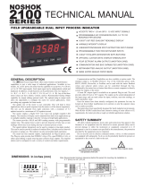
A.3.2. Summary diagram of ways of working
on
on
off
off
HI
-
LO=HI
ACT=NO
activate
deactivate
off
activate
deactivate
on
deactivate
activate
deactivate
activate
on
on
off
off
off
on
off
on
off
on
off
on
off
on
off
off
on
on
on
off
off
off
on
on
on
off
activate
deactivate
activate
deactivate
deactivate
activate
deactivate
activate
off
on
on
off
off
off
on
on
on
off
activate
activate
deacti
vate
deactivate
setpoint
display
activate
activate
PULSE
LATCH
-
1
LATCH
-
2
HI
-
LO=HI
ACT=NC
HI
-
LO=LO
ACT=NO
HI
-
LO=LO
ACT=NC
: Activation edge of alarm where are
done the setpoint functions (RESET, STOP, etc...) and where the relays make LATCH2
: Alarm zone
ON
: Relay and LED activated.
OFF
: Relay and LED deactivated.
A.3.2. Summary diagram of ways of working
on
on
off
off
HI
-
LO=HI
ACT=NO
activate
deactivate
off
activate
deactivate
on
deactivate
activate
deactivate
activate
on
on
off
off
off
on
off
on
off
on
off
on
off
on
off
off
on
on
on
off
off
off
on
on
on
off
activate
deactivate
activate
deactivate
deactivate
activate
deactivate
ac
tivate
off
on
on
off
off
off
on
on
on
off
activate
activate
deactivate
deactivate
setpoint
display
activate
activate
PULSE
LA
TCH
-
1
LATCH
-
2
HI
-
LO=HI
ACT=NC
HI
-
LO=LO
ACT=NO
HI
-
LO=LO
ACT=NC
: Activation edge of alarm where are done the setpoint functions (RESET, STOP, e
tc...) and where the relays make LATCH2
: Alarm zone
ON
: Relay and LED activated.
OFF
: Relay and LED deactivated.

70
70
A.4. Programming setpoint 1 referred to the tachometer (rest of setpoints the same)
S E t P t S3 0
S E t 13 1
o n - o F F3 1 o F F o n - o F F3 1 o n
H I - L o3 1 H I H I - L o3 1 L o
L E V E L3 1
9 9 9 9 9 9
A C t3 1 n o A C t3 1 n c
t - o u t3 1 d L y t - o u t3 1H y S 1 t - o u t3 1
H y S 2
d L y3 1
9 9 9.9
PRO
d L y3 1
9 9 9 9 9.9 d L y3 1
9 9 9 9 9.9
L A t c H3 1 n o L A t c H3 1 Y E S
M o d E3 1
I n d E P M o d E3 1
t r A c K
L E V E L3 1
9 9 9 9 9 9
c o M P3 1P r o c
M o d E3 1
S E n S E
PRO
PRO
A
.4. Programming setpoint 1 referred to the tachometer (rest of setpoints the same)
S E t P t S3 0
S E t 13 1
o n - o F F3 1 o F F o n - o F F3 1 o n
H I - L o3 1 H I H I - L o3 1 L o
L E V E L3 1
9 9 9 9 9 9
A C t3 1 n o A C t3 1 n c
t - o u t3 1 d L y t - o u t3 1H y S 1 t - o u t3 1
H y S 2
d L y3 1
9 9 9.9
PRO
d L y3 1
9 9 9 9 9.9 d L y3 1
9 9 9 9 9.9
L A t c H3 1 n o L A t c H3 1 Y E S
M o d E3 1
I n d E P M o d E3 1
t r A c K
L E V E L3 1
9 9 9 9 9 9
c o M P3 1P r o c
M o d E3 1
S E n S E
PRO
PRO

71
71
SELECTION ON
-
OFF
COMPARISON
If is wanted to refer one o more setpoints to the
instantaneous speed, the variable of comparison will have to
be PROCESS or,
in case of 3 channels PROCESS
-
A.
SPECIAL FUNCTIONS
The setpoint referred to speed can have three specific
functions on the process such as control of value limit
(INDEP), pre-
alarm or safety alarm (TRACK) and indication
of sense of rotation (SENSE).
INDEP.
In independent way, a value is pr
ogrammed of
display above or below which the alarm will be activated.
The value of setpoint corresponds to an instantaneous
speed and does not have sign.
TRACK.
It is used as pre-alarm or saf
ety alarm of the
setpoint that precedes in number. The setpoint that
precedes the number 1 is the number 4.
The value to programming is the distance in points with
regard to the value of setpoint precedent.
The value of display in which the output will be
activated is
the value of the previous setpoint fewer value programmed
like track.
If it was negative, the output would be activated in the
value of the previous setpoint more of track set.
The parameters of functioning are not programmed but
they take dir
ectly of those of the main setpoint.
A.5. Working ways
SELECTION ON
-
OFF
C
OMPARISON
If is wanted to refer one o more setpoints to the
instantaneous speed, the variable of comparison will have to
be PROCESS or, in case of 3 channels PROCESS
-
A.
SPECIAL FUNCTIONS
The setpoint referred to speed can ha
ve three specific
functions on the process such as control of value limit
(INDEP), pre-
alarm or safety alarm (TRACK) and indication
of sense of rotation (SENSE).
INDEP.
In independent way, a value is programmed of
display above or below which the alarm will be activated.
The value of setpoint
corresponds to an instantaneous
speed and does not have sign.
TRACK.
It is used as pre-
alarm or safety alarm of the
setpoint that precedes in number. The setpoint that
precedes the number 1
is the number 4.
The value to programming is the distance in points with
regard to the value of setpoint precedent.
The value of display in which the output will be activated is
the value of the previous setpoint fewer value programmed
like track.
If it wa
s negative, the output would be activated in the
value of the previous setpoint more of track set.
The parameters of functioning are not programmed but
they take directly of those of the main setpoint.
A.5. Working ways

SENSE.
In mode SENSE, the setpoint is not referred to the
speed but to the sense of rotation.
The condition of
alarm takes place when the sense is negative
. That
the output is activated or not will come determined b
y the
parameters HI
-
LO and NO
-
NC.
The sense of rotation determines the direction of count of
the totalizer associated with the channel A, for that only the
configurations in which the channel A can count and
discount can indicate variation of sense.
Thes
e they are: 1 channel, modes 'up-
do', 'dir', 'PH1', 'PH2'
and 'PH4'.
SETPOINT VALUE
The values of setpoint for tachometer are referred to the
variable PROCESS A an
d are programmed without sign and
with the same decimal point that has this variable.
Depending on the setpoint function previously selected, the
programming of this value will be done of the following
ways:
IndEP
: is programm
ed the value of display where the
alarm must be activated.
TrACk
: is programmed of the number of points of display
for below or over the previous setpoint in which there is
activated the alarm used as pre
-
alarm or safety alarm.
SenSE
: no value is programme
d.
SENSE.
In mode SENSE, the setpoint is not referred to the
speed but to the sense of rotation.
The condition of
alarm takes place when the sense is negative
. That
the output is activated or not will come determined by the
parameters HI
-
LO and NO
-
NC.
The sense of rotation determines the direction of count of
the totalizer associated with the channel A, for that only the
configurati
ons in which the channel A can count and
discount can indicate variation of sense.
These they are: 1 channel, modes 'up-
do', 'dir', 'PH1', 'PH2'
and 'PH4'.
SETPOINT
VALUE
The values of setpoint for tachometer are referred to the
variable PROCESS A and are programmed without sign and
with the same decimal point that has this variable.
Depending on the setpoint function previously selecte
d, the
programming of this value will be done of the following
ways:
IndEP
: is programmed the value of display where the
alarm must be activated.
TrACk
: is programmed of the number of points of display
for below or over the previous setpoint in which there
is
activated the alarm used as pre
-
alarm or safety alarm.
SenSE
: no value is programmed.
72
72

18
18
73
73
RANGE OF ACTIVATION
There
are three ways of activating the setpoint output:
DLY.
In way 'dly' delay, the output is activated with a
programmable delay when the condition of alarm having
taken place and maintained, is
deactivated with the same
delay on having eliminated the condition of alarm.
The time of delay is programmable of 0.1s to 999.9s
HYS1.
In way 'hys1' (hysteresis asymmetric) the output is
acti
vated in the value of setpoint and a programmable
number of points is deactivated below the setpoint.
The level of hysteteris is programmable in the whole range
of the display (0 to 999999) with the decimal point in the
position of the display.
HYS2.
In way 'hys2' (hysteresis symmetrical), the output is
activated a programma
ble number of points below the
setpoint and the same number of points is deactivated over
the setpoint.
The number of points is programmable of 0 to 999999 with
the decimal point in the position of the display. The value to
programming will be the half of
the total margin of
hysteresis, that is to say, supposing that the value of
setpoint was 1000 and the value programmed of hysteresis-
2 was 100, the range of display in that the alarm would be
activated between 900 and 1100.
A.6.1. Output mode definition (delay
-
hysteresis, latch, hi
-
lo, no
-
nc)
RANGE OF ACTIVATION
There are three ways of activating the setpoint output:
DLY.
In way 'dly' delay, the output is activated with a
programmable delay when the condition of a
larm having
taken place and maintained, is deactivated with the same
delay on having eliminated the condition of alarm.
The time of delay is programmable of 0.1s to 999.9s
HYS1.
In way 'hys1'
(hysteresis asymmetric) the output is
activated in the value of setpoint and a programmable
number of points is deactivated below the setpoint.
The level of hysteteris is programmable in the whole range
of the display (0 to 999999) with the decimal point
in the
position of the display.
HYS2.
In way 'hys2' (hysteresis symmet
rical), the output is
activated a programmable number of points below the
setpoint and the same number of points is deactivated over
the setpoint.
The number of points is programmable of 0 to 999999 with
the decimal point in the position of the display. Th
e value to
programming will be the half of the total margin of
hysteresis, that is to say, supposing that the value of
setpoint was 1000 and the value programmed of hysteresis-
2 was 100, the range of display in that the alarm would be
activated between 900
and 1100.
A.6.1. Output mode definition (delay
-
hysteresis, latch, hi
-
lo, no
-
nc)

LATCH
The function latc
h is applied when it is necessary to keep an
alarm activated still when the condition of activation has
disappeared. For example to know if, at the conclusion of a
cycle of measurement, the process has exceeded in some
moment a value limit.
no
doest latch the output
YES
Latch the output on the activation edge
When there is selected the option 'YES', the output of
setpoint is activated when the display reaches the
programmed value and it will not be deactivated any more
than i
n a disconnection of the device or by means of the
logical function 26 (in rear conector ).
The output is activated but it is not latched if on having
connected the instrument, the display has a value that is in
condition of alarm. The latch takes place o
nly in the edge of
activation of the output in a step along the setpoint.
MODE
HI
-
LO
In way
HI
the output is activated when the display is equal
or greater than the value of setpoint and is deactivated
when it is less.
In way LO
the output is deactivated when the display is
equa
l or greater than the value of setpoint and is activated
when it is less.
MODE NO
-
NC
NOT
(normally open) it means that the output of setpoint
will be deactivated in rest and activated in co
ndition of
alarm.
NC
(normally closed) means that the output of setpoint will
be activated in rest and will be deactivated when it reaches
the condition of alarm.
LATCH
The function latch is applied when it is nec
essary to keep an
alarm activated still when the condition of activation has
disappeared. For example to know if, at the conclusion of a
cycle of measurement, the process has exceeded in some
moment a value limit.
no
doest la
tch the output
YES
Latch the output on the activation edge
When there is selected the option 'YES', the output of
setpoint is activated when the display reaches the
programmed value and it will not be deactivated any more
than in a disconnection of the de
vice or by means of the
logical function 26 (in rear conector ).
The output is activated but it is not latched if on having
connected the instrument, the display has a value that is in
condition of alarm. The latch takes place only in the edge of
activati
on of the output in a step along the setpoint.
MODE
HI
-
LO
In way
HI
the output is activated when the display is equal
or greater than the value of setpoint and is deactivated
when it is less.
In way LO
the output is deactivated when the display is
equal or greater than the value
of setpoint and is activated
when it is less.
MODE NO
-
NC
NOT
(normally open) it means that the output of setpoint
will be deactivated in rest and activated in condition of
alarm.
NC
(norma
lly closed) means that the output of setpoint will
be activated in rest and will be deactivated when it reaches
the condition of alarm.
74
74

75
75
A.6.2. Summary diagr
am of ways of working
HI
-
LO=HI
ACT=NO
DELAY
HYSTERESIS
-
1
HYSTERESIS
-
2
HI
-
LO=HI
ACT=NC
HI
-
LO=LO
ACT=NO
HI
-
LO=LO
ACT=NC
t
t
activate
deactivate
off
activate
deactivate
on
deactivate
activate
deactivate
activate
off
on
off
on
off
on
off
on
off
on
off
off
on
on
on
off
off
off
on
on
on
off
activar
deactivate
activar
deactivate
deactivate
activate
deactivate
activate
off
on
off
on
off
off
off
on
on
on
activate
activate
deactivate
deactivate
setpoint
display
activate
activate
setpoint
hyst
setpoint+hyst
setpoint
hyst
deactivate
deactivate
off
off
on
on
off
off
on
on
off
on
t
t
t
t
t
t
: Activation edge of alarm where are done the setpoint functions (RESET, STOP, etc...) and where the relays make LATCH2
: Alarm zone
ON
: Relay and LED activated.
OFF
: Relay and LED deactivated.
A.6.2. Summary diagram of ways of
working
HI
-
LO=HI
ACT=NO
DELAY
HYSTERESIS
-
1
HYSTERESIS
-
2
HI
-
LO=HI
ACT=NC
HI
-
LO=LO
ACT=NO
HI
-
LO=LO
ACT=NC
t
t
activate
deactivate
off
activate
deactivate
on
deactivate
activate
deactivate
activate
off
on
o
ff
on
off
on
off
on
off
on
off
off
on
on
on
off
off
off
on
on
on
off
activar
deactivate
activar
deactivate
deactivate
activate
deactivate
activate
off
on
off
on
off
off
off
on
on
on
activate
activate
deactivate
deactivate
setpoint
display
activate
activate
setpoint
hyst
setpoint+hyst
setpoint
hyst
deactivate
deactivate
off
off
on
on
off
off
on
on
off
on
t
t
t
t
t
t
: Activation edge of alarm where are done the setpoint functions (RESET, STOP, etc...) and where the relays make LATCH2
: Alarm zone
ON
: Relay and LED activated.
OFF
: Relay and LED deactivated.

76
76
APPENDIX B. AN
ALOG OUTPUT
The analogical exit is updated every 10ms.
The range o
f the output signal is programmed for any range
of display, being able to be selected like display the
PROCESS (counter or tachometer), the TOTAL or the BATCH
of anyone of the channels (providing that above mentioned
variable is enabled).
A n A o u t4 0
t Y P E4 1 S C A L4 2
t Y P E4 1 U d c t Y P E4 1 I d c c o M P4 2P r o c
A n A - H I4 2
9 9 9 9 9 9
c o M P4 2 t o t
A n A - L o4 2
9 9 9 9 9 9
9 9 9 9 9 99 9
A n A - H I
9 9 9 9 9 99 9
A n A - L o
PRO
PRO PRO
c o M P4 2b t C H
Respect of the instructions of programming that are given in
the manual of the option, the menu has been eliminated
'FILTER' and the programming of the scale has been
modifie
d so that the output range to programming can refer
to any variable that the instrument has enabled.
If the variable is TOTAL, the range is programmed in the
secondary display.
APPENDIX B. ANALOG OUTPUT
The ana
logical exit is updated every 10ms.
The range of the output signal is programmed for any range
of display, being able to be selected like display the
PROCESS (counter or tachometer), the TOTAL or the BATCH
of anyone of the channels (providing that above m
entioned
variable is enabled).
A n A o u t4 0
t Y P E4 1 S C A L4 2
t Y P E4 1 U d c t Y P E4 1 I d c c o M P4 2P r o c
A n A - H I4 2
9 9 9 9 9 9
c o M P4 2 t o t
A n A - L o4 2
9 9 9 9 9 9
9 9 9 9 9 99 9
A n A - H I
9 9 9 9 9 99 9
A n A - L o
PRO
PRO PRO
c o M P4 2b t C H
Respect of the instructions of programming that are given in
the manual of the option, the menu has been eliminated
'FILTER' an
d the programming of the scale has been
modified so that the output range to programming can refer
to any variable that the instrument has enabled.
If the variable is TOTAL, the range is programmed in the
secondary display.

77
77
APPENDIX C. SERIAL OUTPUT RS232C or RS485
PROTOCOLS
It is three protocols of communication represented by the
indication 'Prot-1', 'Prot-2' and 'Prot-3' that correspond to
the protocols DITEL, ISO 1745 and MODBUS respectively.
AVAILABLE COMMANDS
The list of commands that is given in the manual of the
option RS232C ó RS485 must be replaced by the following
one:
Commands
in protocol
1
2
3
hold+reset1
h
0h
h
reset relés latch
n
0n
n
reset de offset
r
0r
r
set offset
t
0t
t
reset1
z
0z
z
Data request in protocol
1
2
va
llue of main display
D
0D
value of auxiliary display
T
0T
Data request and modification in
protocol
2
send setpoint # value
L#
modify setpoint # value
M#
Request and modification of information
in protocol
3
All the information contained in the memory of the
instrument can be read and, if they are in a zone of allowed
writing, modified in blocks of up to 250 bytes. The writing is
limited to the area of information of programming of the
instrument. The reading does not have limitation.
SENDING INFORMATION TO A PRINTER
Through the RS232C ó RS485 output also it is possible to
realize a selective transm
ission of information of the
instrument to a printer or a PC.
The logical functions of printing allow to realize
transmissions from the instrument.
The
format of transmission
consists in:
a character of beginning of message followed by the
direction of the device,
a line in blank,
one or several lines containing the information
according to logical programmed function
And, if it has been selected to print date and hour
two lines in bla
nk,
a line with date and hour
To finish
a line in blank
The functions of printing and how to programme them they
are in the manual present in the section ' 5.2. Logical
programmable functions in connector ', pages.
43 to 46.
APPENDIX C. SERIAL OUTPUT RS232C or RS485
PROTOCOLS
It is three protocols of communication represented by the
indication 'Prot-1', 'Prot-2' and 'Prot-3' that correspond to
the protocols DITEL, ISO 1745 and MODBUS respectively.
AVAILABLE COMMANDS
The list of commands that is given in the manual of the
option RS232C ó RS485 must be replaced by the following
one:
Commands
in protocol
1
2
3
hold+reset1
h
0h
h
reset relés latch
n
0n
n
reset de offset
r
0r
r
set offset
t
0t
t
reset1
z
0z
z
Data request in protocol
1
2
vallue of main display
D
0D
value of auxiliary display
T
0T
Data request and modification in
protocol
2
send setpoint # value
L#
modify setpoint #
value
M#
Request and modification of information
in protocol
3
All the information contained in the memory of the
instrument can be read and, if they are in a zone of allowed
writing, modified in blocks of up to 250 bytes. The writing is
limited to the area of information of programming of the
instrument. The reading does not have limitation.
SE
NDING INFORMATION TO A PRINTER
Through the RS232C ó RS485 output also it is possible to
realize a selective transmission of information of the
instrument to a printer or a PC.
The logical functions of printing allow to realize
transmissions from the instru
ment.
The
format of transmission
consists in:
a character of beginning of message followed by the
direction of the device,
a line in blank,
one or several lines containing the information
according to logical programmed function
And, if it has been selected to print date and hour
two lines in bla
nk,
a line with date and hour
To finish
a line in blank
The functions of printing and how to programme them they
are in the manual present in the section ' 5.2. Logical
programmable functions in connector ', pages.
43 to 46.

7
8
78
The instruments are warranted against defective materials and workmanship for a period of
three
years from date of delivery.
If a product appears to have a defect or fails during the normal use within the warranty
period, please contact the distributor from which you purchased the product.
This warranty does not apply to defects resulting from act
ion of the buyer such as
mishandling or improper interfacing.
The liability under this warranty shall extend only to the repair of the instrument. No
responsibility is assumed by the manufacturer for any damage which may result from its
use.
All the DITEL products benefit from an unlimited and unconditional warranty of THREE (3)
years from the date of their purchase. Now you can extend this peri
od of warranty up to
FIVE (5) years from the product commissioning, only by fulfilling a form.
Fill out the form
in
our website:
http://www.ditel.es/
warranty
The instruments are warranted against defective materials and workmanship for a period of
three years from date of delivery.
If a product appears to have a defect or fails during the normal use within the warranty
period, please contact the dist
ributor from which you purchased the product.
This warranty does not apply to defects resulting from action of the buyer such as
mishandling or improper interfacing.
The liability under this warranty shall extend only to the repair of the instrument. No
responsibility is assumed by the manufacturer for any damage which may result from its
use.
All the DITEL products benefit from an unlimited an
d unconditional warranty of THREE (3)
years from the date of their purchase. Now you can extend
this period of warranty up to
FIVE (5) years from the product commissioning, only by fulfilling a form.
Fill out the form
in
our website:
http://www.ditel.es/
w
arranty
/