Page is loading ...

© 2013 UTC Fire & Security. All rights reserved. 1 / 2 P/N 3101206 • REV 02 • REB 28JAN13
E-SDPCB Duct Smoke Detector PCB
Replacement Kit Installation Sheet
Description
The duct smoke detector PCB replacement kit is used to repair
E-PDD duct smoke detectors in the field. The kit contains a
printed circuit board and two sensing chamber gaskets.
Installation
WARNING: Before replacing the duct smoke detector’s printed
circuit board assembly, notify the proper authorities that the fire
alarm system is undergoing maintenance and take steps to
prevent the control panel from responding to a false alarm.
Caution: This product contains components that are sensitive
to static electricity. Use approved handling precautions to
prevent damage from electrostatic discharge.
To replace the detector printed circuit board:
1. Remove and retain the four screws securing the detector
cover, then remove the cover.
2. Identify the wire locations at the terminal blocks, then
disconnect wires.
3. Note the device address set on the rotary switches, then
set the same device address on the replacement printed
circuit board.
4. Note the position of the JP3 jumper, and then set the
same JP3 jumper setting on the replacement printed
circuit board.
5. Remove and retain the four screws securing the printed
circuit board to the detector housing, and then remove the
printed circuit board.
6. Replace the sensing chamber gasket on the detector
housing with a new gasket from the kit.
7. Secure the replacement printed circuit board to the
detector housing using the four screws previously
removed.
8. Connect the terminal block wiring at the locations marked
during removal.
9. Replace the sensing chamber gasket on the detector
cover with a new gasket from the kit.
10. Secure the detector cover to the detector housing using
the four screws previously removed.
11. Test the detector in accordance with “Testing”.
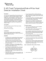
Figure 1: Replacement diagram
Detector housing
Sensing
chamber
gasket
Rotary
switch
HVAC duct
Detector cover
(rear view)
Sensing chamber gasket
PCB assembly
JP3 jumper
4 x 1/4 48-2
plastite screw
(4X)
Airflow
Testing
After replacing the duct smoke detector printed circuit board,
the unit must be tested to ensure it is operating correctly before
leaving the job site. For details, refer to Technical Bulletin
P/N 3101212.

2 / 2 P/N 3101206 • REV 02 • REB 28JAN13
/