Danfoss VLT 5000 (Legacy Product) Operating instructions

Type
Operating instructions

This manual is also suitable for

VLT
®
5000 INTERBUS
MG.10.O1.02  VLT is a registered Danfoss trademark
1
Contents
Chapter 1 Introduction .............................................................. 2
Chapter 2 Interbus introduction ................................................ 4
Chapter 3 Technical Data ......................................................... 5
Chapter 4 Ordering number ...................................................... 6
Chapter 5 Cable routing and Connectors ................................. 7
Chapter 6 Process Data ......................................................... 13
Chapter 7 Drivecom 21 Profile & Interbus objects ................... 15
Chapter 8 FC Profile ................................................................ 23
Chapter 9 VLT Parameters ...................................................... 26
Chapter 10 Timming ................................................................. 30
Chapter 11 Warning and Allarm messages ................................ 31
Chapter 12 Abreviations & definitions ........................................ 32
Chapter 13 VLT5000 Parameter list .......................................... 33
Copyrights, Limitation of Liability and Revision Rights.
This publication contains information proprietary to Danfoss A/S. By accepting and using this manual the user
agrees that the information contained herein will be used solely for operating equipment of Danfoss A/S or
equipment from other vendors provided that such equipment is intended for communication with Danfoss
equipment over a INTERBUS serial communication link. This publication is protected under the Copyright laws
of Denmark and most other countries.
Danfoss A/S does not warrant that a software program produced according to the guidelines provided in this
manual will function properly in every physical, hardware or software environment.
Although Danfoss A/S has tested and reviewed the documentation within this manual, Danfoss A/S makes no
warranty or representation, either express or implied, with respect to this documentation, including its quality,
performance, or fitness for a particular purpose.
In no event shall Danfoss A/S be liable for direct, indirect, special, incidental, or consequential damages arising
out of the use, or the inability to use information contained in this manual, even if advised of the possibility of
such damages. In particular, Danfoss A/S is not responsible for any costs including but not limited to those
incurred as a result of lost profits or revenue, loss or damage of equipment, loss of computer programs, loss of
data, the costs to substitute these, or any claims by third parties.
Danfoss A/S reserves the right to revise this publication at any time and to make changes in its contents
without prior notice or any obligation to notify previous users of such revisions or changes.
MG.10.O1.02  VLT is a registered Danfoss trademark
2
VLT
®
5000 INTERBUS
About this manual
This manual is intended to be used both as an
instructional and as a reference manual. It only
briefly touches on the basics of the INTERBUS
protocol whenever it is necessary for gaining an
understanding of the DRIVECOM implementation of
the DRIVECOM Profile 21
The manual is also intended to serve as a guideline
when you specify and optimize your communication
system.
If you are not completely familiar with INTERBUS,
PCP or the Profile for Variable Speed Drives, it may
be advisable to read some of the material provided
on these subjects.
Even if you are an experienced INTERBUS
programmer, we suggest that you read this manual
in its entirety before you start programming, since
important information can be found in all chapters.
Chapter 5 gives details on the INTERBUS Option
Card and how to establish the physical connection.
In chapter 6 you will find information about VLT
Process Data.
Chapter 7 and 8 describe the two different
statemachine, implemented in the INTERBUS option:
Drivecom 21 and FC Drive.
Chapter 9 has all the relevant VLT and INTERBUS
parameters listed.
Chapter 10 contains information on Timing on a
INTERBUS system and on the INTERBUS option
Chapter 11 describes display messages, warning and
alarm messages.
In chapter 12 you will find a glossary explaining
abbreviations, words and phrases you must know to
understand this manual. This chapter also contains
a complete parameter list with parameter
designations, default settings, setting ranges etc.
Chapter 13 lists the VLT5000 Parameters.
If you want to know more about the INTERBUS
protocol in general, please refer to the vast amount
of literature provided for this purpose.
Assumptions
This manual assumes that you are using a
DANFOSS INTERBUS Option Card in conjunction
with a DANFOSS VLT 5000 Series. It is also
assumed that you, as a master, are using a PLC or
PC that is equipped with a serial communication
card supporting all the INTERBUS communication
services required by your application, and that all
requirements stipulated in the INTERBUS standard
as well as those set up in the DRIVECOM Variable
Speed Drives Profile and its company-specific
implementation, as well as those pertaining to the
VLT Variable Speed Drive are strictly observed as
well as all limitations therein fully respected.
What you should already know
The DANFOSS INTERBUS Option Card is designed
to communicate with any master abiding by the
INTERBUS standard. It is therefore assumed that
you have full knowledge of the PC or PLC you
intend to use as a master in your system. Any
questions pertaining to hardware or software
produced by any other manufacturer is beyond the
scope of this manual and is of no concern to
DANFOSS.
If you have questions about how to set up master -
master communication or communication to a non-
Danfoss slave, the appropriate manuals should be
consulted.
Introduction
VLT
®
5000 INTERBUS
MG.10.O1.02  VLT is a registered Danfoss trademark
3
Available literature
The chart below gives an overview of the literature
available for the VLT 5000 Series.
Please note that variations may occur from one
country to the next.
X = version number
YY = language
01 = Danish
02 = English
03 = German
04 = French
05 = Spanish
06 = Italian
07 = Swedish
10 = Dutch
20 = Finnish
28 = Brazilian Portuguese
51,52 = Danish, English, German
Design
Guide
MG.50.CX.YY
Operating
Instructions
MG.50.AX.YY
Instructions
for VLT
5000 Series
VLT Software
Dialog
MG.50.EX.YY
PROFIBUS
Manual
MG.10.EX.YY
Quick
Setup
MG.50.FX.YY
LCP remote-
mounting kit
IP 20
MI.56.AX.51
Brake
instructions
MI.50.DX.YY
LC-filter
VLT 5001-5011
MI.56.DX.51
IP 20 terminal
cover
MI.56.CX.51
Syncron. and
positioning
MG.10.JX.02
MG.10.JX.03
Gateway
InterBus
MG.10.G1.51
Quick
Setup
MG.50.DX.YY
Quick
Setup
MG.50.GX.YY
Bookstyle IP 20
Compact IP 20
Compact IP 54
VLT 5000
Data sheet
MD.50.AX.YY
Loadsharing
instructions
MI.50.NX.YY
Var. literature
for VLT 5000
Series
Instructions
for VLT 5000
Series
Communication
for VLT 5000
Series
LonWorks
Manual
DeviceNet
Manual
RCD
Instructions
MI.66.AX.YY
Modbus Plus
Manual
LC-filter
VLT 5016-5250
MI.56.FX.51
LCP remote-
mounting kit
IP 54
MI.56.GX.52
VLT 5300-5500
Installation guide
MG.56.AX.YY
Interbus
Manual
MG.10.O1.02  VLT is a registered Danfoss trademark
4
VLT
®
5000 INTERBUS
Technical overview.
Interbus introduction
The INTERBUS system is divided into two different
system: remote and local. The remote system
enables the user to connect up to 256 stations on a
single system wiht a maximum of 400m Cable
between each station.
The locale bus system enables the user to establish
communication to Input/output devices throuhgt a
single twisted pair of Cables. This type of
comunication is typical used the simple devices E.g.
Digital I/O devices.
For Communication on the remote bus the
INTERBUS system provides two different types of
communication Process Data and PCP (Peripherals
Communication Protocol). The Process Data is
cyclic communication to devices with high priority.
This type of communication typically takes between
few milliseconds and up to 100 milliseconds,
depending on the size of the system. Example of
this type of communication is digital & analogue I/O
or control word & reference to frequency
converters.
PCP communication are used for communications
needs that does not require high speed and and
typically only are activated on request from the user
writen program. Typical time to read/write a single
value is 100 to 200 millisecond. Example of this type
of communication is configurating Data, read of
service parameter such as running hours, number
power up and KWh.
VLT
®
5000 INTERBUS
MG.10.O1.02  VLT is a registered Danfoss trademark
5
Technical Data
Technical Data
Topology Ring system - one dual
twisted pair
Physics RS-485
Protocol InterBus, total frame
message transfer
Method Master/Slave
Transmission Asynchronous, full duplex
Trans. Rate 500 Kbits/sec.
Error Check CRC-16
Hamming distance 4
Number of I/O Max. 4096 bits
No. of Nodes Max. 256
Scan Speed 1024 I and 1024 O in less
than 4 ms
Total Distance Max.12.8 km (Cu)
Segm. Length Max. 400 m(~1200 ft.)
between 2 nodes
Cable Belden #8103 or
equivalent
Cable lengths/number of nodes
The maximum length of the Cable is only
provided, if the bus cable has the following
properties :
- Impedance: 135 to 165 ohm at a measuring
frequency from 3 to 20 MHz
- Resistance: < 110 ohm/km
- Capacity: < 30 pF/m
- Damping: max. 9 dB over the
whole wire length
-Cross sect. max. 0.34mm
2,
corresponding to AWG 22
-Cable type: twisted in pairs,
3 x 2, wires
-Screening: Copper-braided screen
or braided screen and foil screen
It is recommended to use the same cable type in
the entire network to avoid impedance
mismatch.
MG.10.O1.02  VLT is a registered Danfoss trademark
6
VLT
®
5000 INTERBUS
Ordering number.
Ordering number.
The Interbus option for the VLT®5000, is available in 2
different versions, one option that serves the purpose
of enabling a VLT®5000 to communicate on a
INTERBUS remote bus as a slave, and one version
that enables the VLT®5000 that is equip with a
Syncronising and positioning option to communicate
on a INTERBUS remote bus as a slave. As upgrade
kit there is also a set of Eproms available.
Field installation:
INTERBUS Option for field installation, complete set
including Interbus Communication unit, Memory
option, EMC Bracket, installation instruction,
manuals. This kit is intended for field installation in
VLT5000 series, that enables a VLT5000 to
communicate on a INTERBUS remote bus.
Ordering number: 175Z3122
Synchronizing and positioning option:
INTERBUS Communication Option, as above, but
wihtout memory option. This option is intended as
and INTERBUS Option to the Synchronizing and
positioning option, that does not need a memory
option and as a spare part for damaged INTERBUS
Option.
Ordering number: 175Z2900
Upgrade Kit:
INTERBUS Memory set. This set contains a full
memory set (3 Pcs.) for the INTERBUS option and
the Memory board. This Option serves as an
upgrade to the latest version of the VLT5000
software and the INTERBUS Communication
option.This options will not upgrade of the
Synchronising and positioning option. Please refere to
the Synchronising and positioning option Manual for
detailed information on how to upgrade this option.
Ordering number: 175Z3123
Factory Installed:
The INTERBUS option can be ordered from Danfoss
Drives, factory installed in a VLT®5000. Please
consult your Danfoss representive for order number of
a given VLT5000 and INTERBUS combination.
VLT
®
5000 INTERBUS
MG.10.O1.02  VLT is a registered Danfoss trademark
7
Cable routing and connectors
recommended to keep the greatest possible
distance between the cables,or use fiber optic
Cables, especially where cables are running in
parallel over long distances.
If the INTERBUS cable has to cross a motor or
brake resistor cable they must cross each other
at an angle of 90° to ensure the minimum of
interfrence.
- Connection of the cable screen
The screen of the INTERBUS cable must
always be connected to ground at both ends,
that means the screen must be connected to
ground in all stations connected to the
INTERBUS network. It is of high importance
to have a low impedance ground connection
of the screen, also at high frequencies.This
can be obtained by connecting the surface of
the screen to ground, for example by means
of a cable clamp or a conductive cable gland.
The INTERBUS Option Card is connected to the
remote bus line via MK 100A or MK 101A for the
incomming INTERBUS cable. terminals 62, 63, 64,
65, and 66. to the bus line via MK 100B or MK 101B
for the outcomming INTERBUS, terminals 62, 63, 64,
65, 66 and RB.
EMC precautions
The following EMC precautions are recommended to
obtain interference free operation of the INTERBUS
network. Additional information on EMC can be found
in the VLT 5000 Series design guide (MG.50.CX.YY).
Please also consult the manual of the INTERBUS
master for further installation guidelines.
Relevant national and local regulations, for
example regarding protective earth connection,
must be observed.
- Cable routing
The INTERBUS communication cable must be
kept away from motor and brake resistor
cables to avoid coupling of high frequency
noise from one cable to the other. Normally a
distance of 200 mm is sufficient, but it is generally
MG.10.O1.02  VLT is a registered Danfoss trademark
8
VLT
®
5000 INTERBUS
LEDs
There are 10 LEDs on the INTERBUS option card.
The LEDs are organized in two sets each having 5
LEDs. One set is visible through the top air outlet if
installed in a VLT®5000 bookstyle, the second set is
visible if installed in a VLT5000 Compact version.
TR
TR
UL
UL
CC/CR
CC/CR
RD
RD
BA
BA
IBS in IBS Out
IBS in
IBS Out
MK 100A MK 100B
MK 101A MK 101B
Name Indicates Color On OFF
CC/CR: Cable Check. Green Incomming bus active Incomming bus swicthed off
BA Bus Active. Green Bus active Bus stopped
RD: Status of outgoing bus. Red Outgoing bus stopped Outgoing bus active
TR: Transmit/Receive. Green PCP Communication running NO PCP Communication running
UL: Power OK. Green Voltage within permissable range No Voltage
VLT 5000 Series is provided with different clamps and
brackets to enable a proper ground connec-aLso at
high frequency. low HF (high frequency) impedance.
This can be achived by connecting a large surface
area of the cabinet to Ground, for example by
mounting the VLT 5000 series on a conductive rear
plate.
Especially when having long distances between
the stations in a INTERBUS network it can be
necessary to use additional potential equalizing
cables, connecting the individual stations to the
same Ground potential.
Connectors
There are 4 connectors, arranged in groups of two.
MK100A and MK100B is to be used if installed in a
VLT®5000 Compact. MK101A and MK101B is used
if the INTERBUS Option is installed in a VLT®5000
Bookstyle. Only one group of connectors may be
used at a time.
Cable routing and connectors
VLT
®
5000 INTERBUS
MG.10.O1.02  VLT is a registered Danfoss trademark
9
Preperation of the Cable for the VLT5000 Connector.
Step 1:
Step 2:
Cable routing and connectors
Interbus Cable DB9 to VLT5000:
Interbus Cable VLT5000 to DB9:
30 mm.
Interbus Cable VLT5000 to VLT5000:
/DO
DO
/DI
DI
COM
RBST
RB
65
66
62
63
64
65
66
62
63
64
/DO
DO
/DI
DI
COM
/DO
DO
/DI
DI
COM
RBST
1
9
6
5
/DO
DO
/DI
DI
COM 3
6
1
7
2
RB
65
66
62
63
64
/DO
DO
/DI
DI
COM
65
66
62
63
64
/DO
DO
/DI
DI
COM
6
3
2
7
1
9
5
1
9
6
5
Green
Yellow
Pink
Gray
Brown
Green
Gray
Pink
Yellow
Brown
Brown
Gray
Pink
Yellow
Green
IBS Out
IBS Out
(Male)
IBS Out
IBS In
IBS In
IBS In
(Female)
MG.10.O1.02  VLT is a registered Danfoss trademark
10
VLT
®
5000 INTERBUS
Interbus Cable VLT©5000 Bookstyle:
Interbus Cable VLT©5000 Compact:
Note: Only ingoing connector set is showed.
Cable routing and connectors
IBS In IBS Out
VLT
®
5000 INTERBUS
MG.10.O1.02  VLT is a registered Danfoss trademark
11
Routing the bus Cable VLT©5060-VLT©5300 IP20 :
Note: Only ingoing cable set is showed.
Cable routing and connectors
MG.10.O1.02  VLT is a registered Danfoss trademark
12
VLT
®
5000 INTERBUS
Routing the bus Cable VLT©5060-VLT©5300 IP54
Note: Only ingoing cable set is showed.
Cable routing and connectors
VLT
®
5000 INTERBUS
MG.10.O1.02  VLT is a registered Danfoss trademark
13
Process Data.
The VLT®5000 INTERBUS option, offers a flexible
way for the user to customize the number of
Process Data. The process Data of the VLT®5000
is split in two main parts: The first two words that is
reserved for the Drive profile and the user
definable Process data (PCD1 to PCD7).
Process Data
The first two words are fixed on the VLT®5000
option, whereas the input and output PCD1 to
PCD7 can be selected by the user. The number of
PCDs active in a system is user selectable from 0
(zero) up to 7 words. The number of PCDs is
always selected in pairs (input and output).
For the first 2 fixed words of Data, in the PQ and PI
Data, the Danfoss VLT®5000 offers two different
types of profiles: Drivecom and Danfoss. The
Drivecom profile fullfills the requirement of Drivecom
21, speed setting 1. The Drivecom and Danfoss
profiles will be explained in detail in chapter 7 & 8.
PCD1 to PCD7 can be used in a flexible way to read
and write the VLT®5000 parameters, or high speed
transfer of data to the Syncronizing and positioning
Card (Sync/Pos Card).
Changing the number of PCDs can be done by
accesing the VLT®5000s Parameter 807. The
Parameter can be changed at any time, but the
changes wil first take place at the next powerup, or if
the Master sends out a Bus reset command.
Please note that changing the number of
PCDs also may change the mapping of the
Masters I/O Area (PC/PLC).
The VLT®5000 INTERBUS option features the
disabling of PQ Data. PQ can be made inactive,
this means that the VLT®5000 ingnores the content
of all PQ Data, but the VLT®5000 continues to
update the PI Data. This feature is used during
reconfiguration of a running VLT®5000 system and
ensures that no parameter is changed by mistake.
The drawing below shows the default setting of a
system with no PCD words. The system only
consist of control word and main reference for the
PQ Data, and status word and main actual value
for the PI Data. In this system the Control word is
mapped into the PLCs output memory QW000
and the reference is mapped to the output memory
QW002. The status word of the VLT®5000 is
mapped into the input word IW000 of the PLC and
the feedback (main actual value) is mapped to
IW002.
Fixed
Fixed
User definable
User definable
PI
PQ
STW
MAV
STW MAV
MRVCTW
CTW
MRV
QW 000
QW 002
IW 000
IW 002
PLC VLT®5000INTERBUS
CTW MRV PCD1 PCD2 PCD3 PCD4 PCD5 PCD
STW MAV PCD1 PCD2 PCD3 PCD4 PCD5 PCD
6
MG.10.O1.02  VLT is a registered Danfoss trademark
14
VLT
®
5000 INTERBUS
Process Data, PCD.
To enable the use of PCD data, of the VLT®5000
INTERBUS option, the amount of PCD Datawords
has to be configured in Parameter 807, where as the
contents of each single PCD word has to be
configured in Parameter 915 and 916. This can be
done in two different ways: setting parameter 915
and 916, or by using the the INTERBUS object
6000
H
and 6001
H
.
After setting parameter 807 to match the desired
amount of PCD Data, the VLT®5000 needs to be
configured, for assigning Parameters to each single
PCD words. The VLT®5000 stores this information
in Parameter 915 and 916. The INTERBUS objects
6000
H
and 6001
H
are images of the two Parameters.
Changing Parameter 915/916 has immidiatly effect
on the PCD data.
The drawing below shows the relation between the
INTERBUS object 6000
H
/6001
H
and VLT®5000
Parameter 915/916.
The INTERBUS Object 6000
H
and 6001
H
is an Array of
words that has following structure:
The sub Index number 1 contains the number of
process data bytes. For each byte of process data
2 sub indexes are used. Sub index 2 contains the
Object number, sub index 3 is the index of the object,
if the object is of type array. The next two indexes are
for the next byte of process data. If a Object is of type
Word it uses 4 Sub indexes, wheras the three last Sub
indexes are not used, and must be set to zero.
The 6000
H
6001
H
Objects can have from 9 up to 37
Sub indexes depending on how many PCD words
there has been assigned. The drawing below shows a
configuration with 2 PCD words assign for reading
parameter 520 (Current) and parameter 528 (digital
input). For writing parameter 204 (minimum reference)
and parameter 221 (Torque limit) is used.
The output data to the VLT®5000 can be disabled by
Interbus Object 6002
H
. By setting the Interbus object
6002
H
to 00
H
all imcomming process data wil not be
transimitted to the VLT5000. Setting Interbus object
6002
H
to FF
H
reactivates the updating of output data.
After a power up the option always sets objects 6002
H
to FF
H
.
Writing to Interbus Object 6001
H
automaticly sets object 6002
H
to 00
H
an
thereby disables the inputs. The user has
to write 0FF
H
to Object 6002
H
manually.
Process Data
Bytes of PQ/PI Data
Description
Object number
Object number
Sub Index
Object number
Sub Index
Sub Index
Object number
Sub Index
Data type
Unsigned 8
Unsigned 8
Unsigned 16
Unsigned 16
Unsigned 16
Unsigned 8
Unsigned 8
Unsigned 16
Unsigned 8
Sub index
1
2
3
4
6
5
9
8
7
37 Unsigned 8
Sub Index
STW
MAV
PCD2
PCD1
CTW
MRV
PCD2
PCD1
6001
17
6040
00
0000
00
6042
00
0000
00
56BC
00
0000
00
56CD
00
0000
00
6000
17
6041
00
0000
00
6044
00
0000
00
57F8
00
0000
00
5900
00
0000
00
204
0
0
0
0
0
221
915 [1]
520
0
0
0
0
0
528
916
MRV PCD1
PCD2CTW
STW MAV PCD1
PCD2
915 [2]
{
PCD2
{
PCD1
{
MRV
{
CTW
{
STW
{
MAV
{
PCD1
{
PCD2
Interbus ob
j
ects
VLT5000
Parameters
916 [1]
916 [2]
IW 000
IW 002
QW 002
QW 000
VLT
®
5000 INTERBUS
MG.10.O1.02  VLT is a registered Danfoss trademark
15
Drivecom State machine
The state machine describes the device status and
the possible control sequence of the drive. A status
represents a specific internal and external response.
By means of device control commands and/or
internal events, the status can be changed and a
control sequence thus executed. The current status
can be read out by way of the VLT®5000 status word.
In the flowchart to the right, this explanation may help
you understanding the
drawing: to change from
state A to state B, the condition Controlword bit 1
has to be set equal to 0. The coarses the
transition 0 to be exequted. In state B the
statusword is equal to xx01
H
.
Drivecom 21 Profile.
Not ready to switch on
STW = xx00h
Switched on
0
1
2
11
7
3
4 5
6
9
8
12
10
STW = xx33h
Disable Voltage
xxxx xx0x or
Qiuck stop
xxxx x01x
Shutdown
xxxx x110
Disable Voltage
xxxx xx0x
Switch on
xxxx x111
Stop
xxxx x110
Enable
operation
xxxx 1111
Disable
operation
xxxx x01x
Shutdown
xxxx x110
Qiuck stop
xxxx x01x
Disable voltage
xxxx xx0x
Disable voltage
xxxx xx0x or
Quick stop
xxxx x01x
Reset malfunction
0xxx xxxx
1xxx xxxx
Operation enabled
STW = xx37h
Enabled Ramp
STW = xx37h
No Freeze
STW = xx37h
Start
STW = xx37h
Quick stop active
STW = xx17h
13
14
15
STW = xx38h
STW = xxxx xxxx x1xx 1xxx
JOG 1
STW = xx37h
Malfunction reaction
active
Malfunction
Read
y
to switch on
STW = xx31h
Switch on disabled
STW = xx40h
Power on
Drivecom 21
Danfoss specific
State B
STW = xx01h
0
State A
condition
xxxx xx0x
transition 0
MG.10.O1.02  VLT is a registered Danfoss trademark
16
VLT
®
5000 INTERBUS
Data transitions of the device control
The following describes each transaction that the
Drivecom statemachine follows, by a given
command.
0 Input of the state machine NOT READY TO
SWITCH ON
Event: - Reset
Action: - Start self test
- Start initialisation
1 NOT READY TO SWITCH ON SWITCH ON
DISABLED
Event: - Error-free self test
- Initialisation completed without errors occurring
Action: - Activate communication and process data
monitoring
2 SWITCH ON DISABLED READY TO SWITCH
ON
Event: - Shutdown command
Condition: - Depending on the manufacturer-specific
requirements (e.g. power section ready)
Action: - None
3 READY TO SWITCH ON SWITCHED ON
Event: - Switch-on command
Action: - The power section is switched on if it is not
already switched on.
4 SWITCHED ON OPERATION ENABLED
Event: - Enable-Operation command
Action: - Enable drive function
5 OPERATION ENABLED SWITCHED ON
Event: - Disable-Operation command
Action: - Execute the parameter-definable Drive-
Disable-Function
6 SWITCHED ON READY TO SWITCH ON
Event: - Shutdown command
Action: - The power section can be switched off
7 READY TO SWITCH ON SWITCH ON DIS-
ABLED
Event: - Quick-Stop or Disable-Voltage com-
mand
Action: - None
8 OPERATION ENABLED READY TO SWITCH
ON
Event: - Shutdown command
Action: - Execute the parameter definable Drive-
Disable-Function
- The power section can be switched off
9 OPERATION ENABLED SWITCH ON DISABLED
Event: - Disable-Voltage command
Action: - Disable drive function
- The power section can be switched off
10 SWITCHED ON SWITCH ON DISABLED
Event: - Disable-Voltage command
or
- Quick-Stop command
Action: - The power section can be switched off
11 OPERATION ENABLED QUICK STOP ACTIVE
Event: - Quick-Stop command
Action: - Trigger the parameter-definable Quick-
Stop-Function
12 QUICK STOP ACTIVE SWITCH ON DISABLED
Event: - Quick stop has been completed
or
- Disable-Voltage command
Action: - Disable drive function
- The power section can be switched off
13 All states MALFUNCTION REACTION ACTIVE
Event: - Drive malfunction detected
Action: - Trigger malfunction reaction depending on
the fault
14 MALFUNCTION REACTION ACTIVE MAL-
FUNCTION
Event: - Malfunction reaction concluded
Action: - Disable drive function
- The power section can be switched off
15 MALFUNCTION SWITCH ON DISABLED
Event: - Malfunction-Reset command
Condition: - Malfunction is no longer present
Action: - Malfunction reset is executed
Drivecom 21 Profile.
VLT
®
5000 INTERBUS
MG.10.O1.02  VLT is a registered Danfoss trademark
17
Control word as per Drivecom 21 Standard
(parameter 512 = Drivecom)
MasterSlave
15 14 13 12 11 10 9 8 7 6 5 4 3 2 1 0 Bit
no.
Bit Bit = 0 Bit =1
00 Switch off Switch on
01 Disable voltage Enable voltage
02 Quick stop Run
03 Disable operation Enable operation
04 Disable Ramp Enable Ramp
05 Freeze Run enable
06 Ramp stop Start
07 No function Reset
08 Drivecom reserved
09 Drivecom reserved
10 Drivecom reserved
11 Jog 1 OFF Jog 1 ON
12 Danfoss reserved
13 Choice of Setup 1 (lsb)
14 Choice of Setup 2 (msb)
15 Forward Reversing
Bit 00, Switch OFF/ON:
Bit 00= "0" execute transition 2, 6 or 8
Bit 00 = "1" execute transition 3
Bit 01, Disable/Enable Voltage:
Bit 01= "0" execute transition 9, 10 or 12
Bit 01 = "1" = Enable Voltage
Bit 02, Quick stop/Run:
Bit 02= "0" execute transition 7, 10 or 11.
Bit 02 = "1" = Quick stop not active.
Bit 03, Disable/enable Operation:
Bit 03= "0" execute transition 5.
Bit 03 = "1" = Enable operation
Bit 04, Quick-stop/ramp:
Bit 04= "0" execute transition 7 or 11, Quick stop
Bit 04 = "1" = Enable ramp.
Bit 05, Freeze output frequency/ramp enable:
Bit 05 = "0" means that the given output frequency is
maintained even if the reference is changed.
Bit 05 = "1" means that the frequency converter is
again able to regulate, and the given reference is
followed.
Bit 06, Ramp stop/start:
Bit06= "0" The VLT controls the motor down to
stop.
Bit 01 = "1" = Start command to the VLT is given
Bit 07, No function/reset
Reset of trip. Bit 07 = "0" means that there is no
reset. Bit 07 = "1" means that a trip is reset.
Bit 08, 09 and 10 :
Drivecom reserved.
Bit 11, Jog 1 OFF/ON:
Activation of pre-programmed speed in
parameter 509 (Bus JOG 1). JOG 1 is only
possible when Bit 04 = "0" and bit 00-03 = "1".
Bit 12,:
Danfoss reserved.
Bits 13/14, Choice of Setup:
Bits 13 and 14 are used for choosing among the
four menu Setups in accordance with the
following table:
Setup Bit 14 Bit 13
10 0
20 1
31 0
41 1
Bit 15, No function/reversing:
Reversing of the direction of rotation of the motor.
Bit 15 = "0" leads to no reversing, bit 15 = "1"
leads to reversing.
Please note that, in the factory setting, reversing
has been chosen as digital in parameter 506,
which means that bit 15 will only lead to reversing
if bus, logic or or logic and (however, logic and
only together with terminal 19) has been
selected.
NB!
Unless otherwise mentioned, the control
word bit is combined (gated) with the
corresponding function on the digital
inputs as a logical "or" function.
Drivecom 21 Profile.
Control
word
Bus
reference
MG.10.O1.02  VLT is a registered Danfoss trademark
18
VLT
®
5000 INTERBUS
Status word (according to Drivecom standard)
The status word is used for informing the master
(e.g. a PC) of the condition of the VLT 5000.
SlaveMaster
15 14 13 12 11 10 9 8 7 6 5 4 3 2 1 0 Bit
no.
Bit Bit = 0 Bit =1
00 Not ready to Ready to
switch on switch on
01 Switched off Switched on
02 Operation disabled Operatin enabled
03 No malfunction Malfunction
04 Voltage disabled Voltage Enable
05 Quick stop Run
06 Switch on disable Switch on
enable
07 No warning Warning
08 Danfoss reserved
09 Remote disabled Remote enabled
10 Setpoint not reached Setpoint reached
11 Speed limit Speed limit
not active active
12 Drivecom reserved
13 Drivecom reserved
14 Not running Running
15 Danfoss reserved
Bit 00, Not ready to switch on/Ready to switch on:
Bit 00 = "0" state less than ´´Ready to switch on
Bit 00 = "1" state at least = ´´Ready to Switch on
Bit 01, Switch off/Switch on:
Bit 00 = "0" state less than ´´Switched on
Bit 00 = "1" state at least = ´´Switched on
Bit 02, Operation disable/Operation enable:
Bit 00 = "0" state less than ´´Operation enable
Bit 00 = "1" state at least = ´´Operation enable
Bit 03, No fault/trip:
Bit 03 = "0" means that VLT 5000 Series is not in a
fault condition. Bit 03 = "1" means that VLT 5000
Series has tripped and needs a reset signal in order
to run.
Bit 04, Voltage disable/Voltage enable:
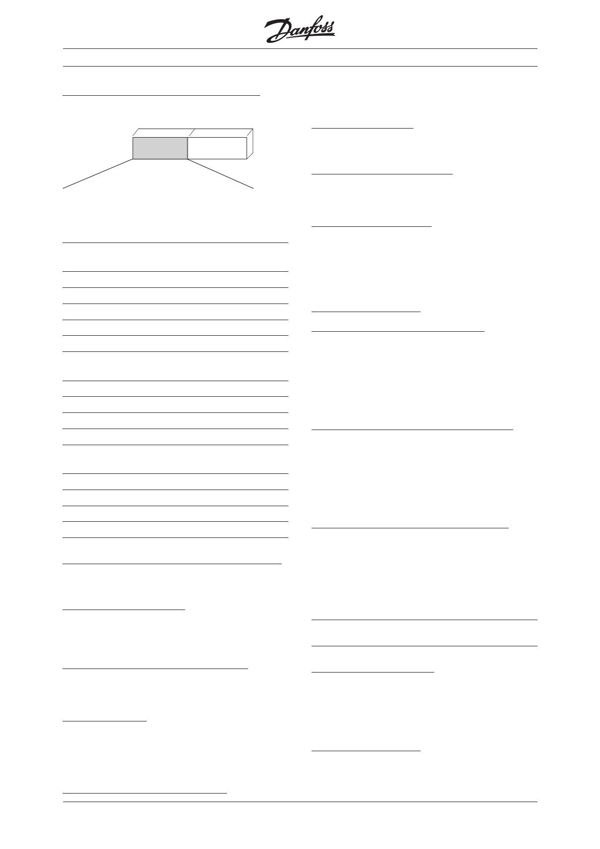
Output
frequency
Status
word
Bit 04 = "0" means that control word bit 01 = "1".
Bit 04 = "1" means that control word bit 01 = "0".
Bit 05, Quick stop/Run:
Bit 05 = "0" means that control word bit 02 = "1".
Bit 05 = "1" means that control word bit 02 = "0".
Bit 06, Start enable/start disable:
Bit 06 = "0" state not ´´Switch on disable
Bit 06 = "1" state = ´´Switch on enable
Bit 07, No warning/warning:
Bit 07 = "0" means that there is no unusual
situation. Bit 07 = "1" means that an abnormal
condition has arisen for the VLT 5000 Series. All
warnings are described in the Operating
Instructions.
Bit 08, Danfoss reserved:
Bit 09, Remote disable/ Remote enable:
Bit 09 = "0" means that VLT 5000 Series has been
stopped by means of the stop key on the control
panel, or that Local operation has been selected in
parameter 002. Bit 09 = "1" means that it is
possible to control the frequency converter via the
serial port.
Bit 10, Setpoint not reached/Setpoint reached:
Bit 10 = "0" means that the actual motor speed is
different from the speed reference set. This can be
the case i.a. while the speed is ramped up/down
during start/stop. Bit 10 = "1" means that the
present motor speed equals the speed reference
set.
Bit 11, Speed limit not active/speed limit active:
Bit 11 = "0" means that the output frequency is out
of the range set in parameter 225 (Warning: Low
frequency) and parameter 226 (Warning: High
frequency). Bit 11 = "1" means that the output
frequency lies within the mentioned range.
Bit 12, Drivecom reserved
Bit 13, Drivecom reserved
Bit 14, Running/Not running:
Bit 14 = "0" means that the motor is not running.
Bit 14 = "1" means that VLT 5000 Series has a start
signal or that the output frequency is greater than 0
Hz.
Bit 15, Danfoss reserved.
Drivecom 21 Profile.
VLT
®
5000 INTERBUS
MG.10.O1.02  VLT is a registered Danfoss trademark
19
Bus reference value (Drivecom Profile):
MasterSlave
1514131211109876543210Bit no.
The bus reference value is transmitted to the frequency
converter in the form of a 16-bit word. The value is
transmitted as a whole number (-32768 to 32767). The
value is handled as RPM.
Actual output RPM
SlaveMaster
1514131211109876543210Bit no.
The value of the actual output RPM of the Motor, is
transmitted in the form of a 16-bit word. The value is
transmitted as a whole number (-32768 to 32767).
Drivecom 21 Profile.
Status
word
Output
frequency
Control
word
Bus
reference
MG.10.O1.02  VLT is a registered Danfoss trademark
20
VLT
®
5000 INTERBUS
Drivecom 21 objects.
The VLT®5000 supports 9 Drivecom specific objects.
The objects can be access by PCP communication.
4 of these objects can also be accessed as process
data.
Object 6040
H
, Control Word:
This object is the same as the Drivecom Control Word
Object 6041
H
, Status Word:
This object is the same as the Drivecom status word .
Object 6042
H
, Nominal-Speed-Value :
This object is the same as the Bus reference (MRV).
Object 6043
H
, Reference-Speed-Variable:
This is the reference after the Ramp. This value is read
only (-32768 to 32767) .
Object 6044
H
, Actual-Speed-Value:
This object is the same as the Actual output RPM.
The value of the actual output RPM of the Motor, is
transmitted in the form of a 16-bit word. The value is
transmitted as a whole number (-32768 to 32767).
Object 6046
H
, Speed-min-max-amount:
The Speed-Min-Max-Amount Object is composed of
the Speed-Min-Amount and Speed-Max-Amount sub
objects. These subobjects have no unit and have val-
ues within a range from 0 to 4 294 967 295 (unsigned
32).The Interbus Option translates these two indexes
into the VLT®5000 parameter 204 and 205. Based on
Parameter 106 (Motor Norminal Speed) the option
calculation new values for P.204 & P.205.
Object 6048
H
, Speed-Acceleration:
The Speed-Acceleration object specifies the slope of
the acceleration ramp (α) The object has 2 indexes
where: Index 1, is the Delta-Speed (unsigned 32) and
index 2 is Delta-Time (unsigned 16). If Delta-Time is
set to 0 (zero) the ramp is disabled. The VLT®5000
Interbus Option translate these two values into the
VLT®5000 parameters 106, Motor norminal speed
and parameter 207, ramp up time.
Object 6049
H
, Speed-Deceleration:
The Speed-deceleration object specifies the slope of
the deceleration ramp (α) The object has 2 indexes
where: Index 1, is the Delta-Speed (unsigned 32) and
index 2 is Delta-Time (unsigned 16). If Delta-Time is
set to 0 (zero) the ramp is disabled. The VLT®5000
Interbus Option translate these two values into the
VLT®5000 parameters 106, Motor norminal speed
and parameter 208, ramp down time.
T, time
N, Rpm
n
t
αα
αα
α
T, time
N, Rpm
n
t
αα
αα
α
The VLT®5000 will first activate the
changes when both indexes are written.
Since the VLT®5000 translates the two
indexes into VLT®5000 paramters, the
value written to Object 6048
H
may be dif-
ferent from a following read, but the slope
(α) is correct !
The VLT®5000 will first activate the changes
when both indexes are written. Since the
VLT®5000 translates the two indexes into
VLT®5000 paramters, the value written to
Object 6049
H
may be different from a follow-
ing read, but the slope (α) is correct !
Object 603F
H
, Malfunction:
This is the errors reported back to the Master system.
A detailed list is on the next page.
Object 6052
H
, Normial-Percentage :
This object is the Normial setpoint in %. . The value is
transmitted as a whole number ±100% = ±4000
H.
This value is read only.
Object 6054
H
, Actual-Percentage :
This object is the actual speed of the motor . The
value is transmitted as a whole number ±100% =
±4000
H
Drivecom 21 Objects
  • Page 1 1
  • Page 2 2
  • Page 3 3
  • Page 4 4
  • Page 5 5
  • Page 6 6
  • Page 7 7
  • Page 8 8
  • Page 9 9
  • Page 10 10
  • Page 11 11
  • Page 12 12
  • Page 13 13
  • Page 14 14
  • Page 15 15
  • Page 16 16
  • Page 17 17
  • Page 18 18
  • Page 19 19
  • Page 20 20
  • Page 21 21
  • Page 22 22
  • Page 23 23
  • Page 24 24
  • Page 25 25
  • Page 26 26
  • Page 27 27
  • Page 28 28
  • Page 29 29
  • Page 30 30
  • Page 31 31
  • Page 32 32
  • Page 33 33
  • Page 34 34
  • Page 35 35
  • Page 36 36
  • Page 37 37
  • Page 38 38

Danfoss VLT 5000 (Legacy Product) Operating instructions

Type
Operating instructions
This manual is also suitable for

Ask a question and I''ll find the answer in the document

Finding information in a document is now easier with AI