
PRODUCT DATA
60- 2061- 10
® U.S. Registered Trademark
Copyright © 2001 Honeywell • All Rights Reserved
L8124A,B,C,E,G,L,M
Aquastat® Relays
GENERAL
These immersion type controllers are for use with forced
hydronic heating systems that include domestic hot water
service.
FEATURES
• L8124 Aquastat® Relays provide high limit, low limit,
and circulator control for maintaining boiler
temperatures.
• L8124 Aquastat Relays can provide multizone control
by using a separate circulator and R845 Relay for
each zone.
• All L8124 Aquastat Relays mount directly on the boiler.
• L8124E,G and L have large transformers and extra
terminals for supplying power to low voltage zone
valves.
• L8124M is for use in a wood-coal/gas-oil multifuel
heating system. Circulator is independently controlled
by the thermostat.
Contents
General ............................................................................. 1
Features ........................................................................... 1
Specifications ................................................................... 2
Ordering Information ........................................................ 2
Installation ........................................................................ 5
Wiring ............................................................................... 7
Operation .......................................................................... 10
Setting And Checkout ....................................................... 10
Checkout .......................................................................... 14
Material Safety Data Sheet (MSDS) ................................. 14

L8124A,B,C,E,G,L,M AQUASTAT® RELAYS
60-2061—10 2
ORDERING INFORMATION
When purchasing replacement and modernization products from your TRADELINE® wholesaler or distributor, refer to the
TRADELINE® Catalog or price sheets for complete ordering number.
If you have additional questions, need further information, or would like to comment on our products or services, please write or
phone:
1. Your local Home and Building Control Sales Office (check white pages of your phone directory).
2. Home and Building Control Customer Relations
Honeywell, 1885 Douglas Drive North
Minneapolis, Minnesota 55422-4386
In Canada—Honeywell Limited/Honeywell Limitée, 35 Dynamic Drive, Scarborough, Ontario M1V 4Z9.
International Sales and Service Offices in all principal cities of the world. Manufacturing in Australia, Canada, Finland, France,
Germany, Japan, Mexico, Netherlands, Spain, Taiwan, United Kingdom, U.S.A.
SPECIFICATIONS
IMPORTANT
The specifications given in this publication do not
include normal manufacturing tolerances. Therefore,
this unit may not exactly match the listed
specifications. Also, this product is tested and
calibrated under closely controlled conditions, and
some minor differences in performance can be
expected if those conditions are changed.
TRADELINE® Models
TRADELINE models are selected and packaged for ease of
handling, ease of stocking, and maximum replacement value.
TRADELINE model specifications are the same as those of
standard models except as noted in Table 1.
Tradeline Models Available L8124B,E,G,L Aquastat Relays
without well and spud.
Additional Features:
• Heat-conductive compound for better bulb response in
oversized well.
• Case can be vertically or horizontally mounted.
• Field-addable limit stops.
• TRADELINE pack with cross reference label and special
instructions.
Pressure Rating:
200 psi (1380 kPa) on outside of immersion well.
100 psi (690 kPa) on capsule if inserted directly.
Maximum Ambient Temperature:
Case: 150°F (66°C).
Sensing element: 265°F (129°C).
Thermostat Heat Anticipator Setting: 0.2A.
Low Limit:
Setting: 110°F to 220°F, adjustable (43°C to 104°C).
Differential: 10°F to 25°F, adjustable (6°C to 14°C).
High Limit:
Setting: 130°F to 240°F, adjustable (54°C to 116°C).
Differential: 10°F, fixed (6°C).
Mounting Means: 1/2 or 3/4 in. taper pipe threaded.
Dimensions: See Fig. 1 and 2.
Sensing Element: 3/8 x 2-7/8 in (10 x 73 mm).
Insulation Depth: 1-1/2 or 3 in. (38 or 76 mm);
see Fig. 1 and 2.
Insertion Length: 3-3/8 in. (86 mm).
Approvals:
Underwriters Laboratories Inc.:
Listed (L8124 models with well): File No. MP466,
Guide No. MBPR.
Component Recognized (L8124 Models Without Well):
File No. MP466, Guide No. MBPR2.
Canadian Standards Association:
Component Recognized: File No. LR1620,
Guide No. 400-E-O.

L8124A,B,C,E,G,L,M AQUASTAT® RELAYS
3 60-2061—10
Table 1. Aquastat Relay models.
a
Multizone control can be provided by using a separate circulator and R845 Relay for each zone.
b
Contacts are not powered; they are rated for switching of millivoltage loads.
Replacement Aquastat Assemblies:
See Table 2 and Fig. 3 through 7.
Table 2. Replacement Aquastat assemblies.
Model
Number
Burner
Control
Circuit
Case Dimensions
Can be
Used For
Multizone
With
Circulators
a
No. of V8043
Zone Valves
Powered
Without
Additional
Transformer
Electrical
Ratings
Height Width Depth
in. mm in. mm in. mm
Burner
Circuit
Circulat
or
Circuit
Mounting
L8124A 120V 6-1/8 156 4-3/8 111 3-1/16 78 Yes — Same as
L8124A-G,L
circulator
rating
120 Vac:
7.4A (full
load);
44.4A
(locked
rotor)
Vertical
L8124B
b
6-1/8 156 4-3/8 111 3-1/16 78 — — 0.25A at 1/4
to 12 Vdc
Vertical or
horizontal
L8124C 120V 4-3/8 111 6-1/8 156 3-1/16 78 Yes — Same as
L8124A-G,L
circulator
rating
240
Vac:3.7A
(full
load);
22.2A
(locked
rotor)
Horizontal
L8124E 24V 6-1/8 156 4-3/8 111 3-1/16 78 Yes 2 1.25A at 24
Vac; 30 VA
(total load)
B1-B2 TV-Z
Vertical or
horizontal
L8124G 120V 6-1/8 156 4-3/8 111 3-1/16 78 — 2 Same as
L8124A-G,L
circulator
rating
L8124L 120V 4-3/8 111 6-1/8 156 3-1/16 78 Yes 2 Same as
L8124A-6,L
circulator
rating
L8124M 120V 4-3/8 111 6-1/8 156 3-1/16 78 Yes — Same as
L8124A
Horizontal
Model
Fahrenheit
Celsius (L8124A,
100/220V Model Only)
1-1/2 in. or 3 in. (38
or 76 mm) insulation
1-1/2 in. or 3 in. (38
or 76 mm) insulation
L8124A-C,
E,G,L,M
125026AAE 125026BAC

L8124A,B,C,E,G,L,M AQUASTAT® RELAYS
60-2061—10 4
Fig. 1. L8124 mounting dimensions in in. (mm).
Fig. 2. Immersion well dimensions. (Refer
to form 68-0040, Wells and Fittings for
Temperature Controllers, to order well.)
Fig. 3. Internal view of L8124A and C.
Fig. 4. Internal view of L8124B.
3-1/8
(79)
1/8 (3)
6
-1/8
(
156)
3-3/8
(86)
2-1/8 (54)
(VERTICAL
MOUNT)
1-1/4 (32) (HORIZONTAL
MOUNT—BOTTOM)
KNOCKOUTS FOR
1/2 (13) CONDUIT
4-5/16 (110)
1-1/4 (32)
(VERTICAL
MOUNT)
3-1/16 (78)
(HORIZONTAL
MOUNT)
M892
5
CONTROL
MOUNT
FITS BOILER TAPPED HOLE
1/2 OR 3/4 IN. NPT
INSULATION
LENGTH 1-1/2
OR 3 IN.
(38 OR 76 MM)
INSERTION
LENGTH
3-3/8 IN.
(86 MM)
M1797
M8961
VOLTAGE
BARRIER
TRANSFORMER
FOR THERMOSTA
T
CIRCUIT
DIFFERENTIAL
SETTING
CIRCULATOR
RELAY
LOW LIMIT
SETTING
HIGH LIMIT
SETTING
M8964
TRANSFORMER
FOR THERMOSTA
T
CIRCUIT
DIFFERENTIAL
SETTING
CIRCULATOR
RELAY
LOW LIMIT
SETTING
HIGH LIMIT
SETTING
GROUND SCREW

L8124A,B,C,E,G,L,M AQUASTAT® RELAYS
5 60-2061—10
Fig. 5. Internal view of L8124E.
Fig. 6. Internal view of L8124G and L.
Fig. 7. Internal view of L8124M.
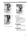
INSTALLATION
When Installing This Product…
1. Read these instructions carefully. Failure to follow
them could damage the product or cause a
hazardous condition.
2. Check the ratings given in the instructions and on
the product to make sure the product is suitable for
your application.
3. Installer must be a trained, experienced service
technician.
4. After installation is complete, check out product
operation as provided in these instructions.
WARNING
Fire or Explosion Hazard.
Can cause severe injury, death or property
damage.
Product is for use only in a system with a pressure
relief valve.
WARNING
Electrical Shock Hazard.
Can cause severe injury, death or property
damage.
Disconnect power supply before beginning installation
to prevent electrical shock or equipment damage.
M8962
TRANSFORMER
FOR THERMOSTA
T
CIRCUIT
DIFFERENTIAL
SETTING
CIRCULATOR
RELAY
LOW LIMIT
SETTING
HIGH LIMIT
SETTING
GROUND SCREW
M8853
DIFFERENTIAL
SETTING
LOW LIMIT
SETTING
GROUND
SCREW
HIGH LIMIT
SETTING
TRANSFORMER
FOR THERMOSTA
T
CIRCUIT
CIRCULATOR
RELAY
M8963
VOLTAGE
BARRIER
TRANSFORMER
FOR THERMOSTA
T
CIRCUIT
DIFFERENTIAL
SETTING
CIRCULATOR
RELAY
LOW LIMIT
SETTING
HIGH LIMIT
SETTING
GROUND SCREW

L8124A,B,C,E,G,L,M AQUASTAT® RELAYS
60-2061—10 6
IMPORTANT
1. Terminals on these Aquastat relays are approved
only for copper wire.
2. Immersion well must snugly fit sensing element and
bulb must rest against bottom of well. Bend the
tubing, if necessary, to hold bulb against the bottom
of the well. Do not make a sharp bend in the tubing
that can produce a break in the tubing and cause
loss of fill. This condition will cause the high and low
limit controllers to be made continuously.
Mounting Standard Models
The boiler must be provided with a tapping that allows
horizontal mounting of the well. It should be located where
boiler water of average temperature can circulate around the
well.
To mount the L8124, proceed as follows:
1. Turn off all power and drain the boiler.
2. If no tapping is provided, prepare one that is properly
sized and threaded at the location selected.
3. Install the immersion well (ordered separately) in the
boiler tapping and tighten securely.
NOTE: Do not attempt to tighten the well using the case as a
handle.
4. Refill the boiler and check for water leakage.
5. Loosen, but do not remove, the clamp screw on the
bottom (L8124A,B,E,G) or on the top (L8124C,L,M)
of the case.
6. Insert the element in the well until it bottoms.
7. Fit the case onto the well so that the clamp on the case
slides over the flange on the well. Securely tighten the
clamp screw.
TRADELINE Models
IMPORTANT
Use the heat-conductive compound furnished with
the TRADELINE L8124 to obtain best thermal
response. Fold the plastic bag of compound
lengthwise and twist it gently. Snip off end and work
open end of the bag all the way into the well. Slowly
pull out the bag while firmly squeezing it to evenly
distribute the compound.
Position the mounting bracket on the back of the case for
mounting the case horizontally or vertically as desired. See
Fig. 8.
1. Shut off the electric power and remove the old control.
Leave the old immersion well in place if it is suitable for
use with the L8124, either with or without an adapter. A
124904 Well Adapter can be ordered separately; see
form 68-0040, Immersion Wells and Compression
Fittings, for ordering information.
2. If the old well is unsuitable, drain the system, remove
the old well, and install a new immersion well. Refill the
system. Refer to form 68-0040, Wells and Fittings for
Temperature Controllers, to order a new well. Make
sure the well is tightly screwed in to prevent leakage.
NOTE: Do not attempt to tighten the well using the case as a
handle.
3. Loosen, but do not remove, the immersion well clamp
screw.
4. If the immersion well fits the L8124 Immersion Well
Clamp, proceed as follows:
a. Partially fill the immersion well with heat-conductive
compound.
b. Insert the bulb into the well. The bulb must bottom in
the well.
c. Make sure the well fits into the hole in the case.
Properly position the clamp on the well flange; then
tighten the clamp screw.
d. Center the loop of excess capillary tubing in front of
the immersion well so it cannot touch any electrical
parts.
NOTE: Some models have a tubing length adjustable to
3 in. (76 mm). In these models, pull out extra tubing
from inside the case if needed.
5. If the old immersion well is otherwise suitable but does
not fit the L8124 Clamp, a 124904 Well Adapter,
ordered separately, must be used as follows:
a. After loosening the immersion well clamp screw, fit
the adapter onto the capillary tube (Fig. 9).
b. Make sure the adapter fits into the hole in the case.
Properly position the clamp on the adapter flange;
then tighten the clamp screw.
c. Return to step 4a above, and complete the
installation.
Fig. 8. Convertible case on tradeline models is
designed for horizontal or vertical mounting.
BRACKET POSITION FOR
VERTICAL MOUNTING
BRACKET POSITION FOR
HORIZONTAL MOUNTING
M179
8

L8124A,B,C,E,G,L,M AQUASTAT® RELAYS
7 60-2061—10
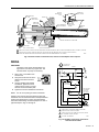
Fig. 9. Position of bulb in immersion well, and use of well adapter when required.
WIRING
IMPORTANT
Terminals on the L8124 Aquastat Relay are
approved for use with only copper wire. The
terminals allow only wrap-around wiring.
1. Strip 7/16 in. of insulation from
the wire end.
2. Wrap the wire at least 3/4 of the
distance around the screw as
shown.
3. Using a standard, flat-headed
screwdriver, tighten the screw
until the wire is snugly in contact
with the screw and contact plate.
4. Tighten the screw an additional one-half turn.
NOTE: Do not use a push-type ratchet screwdriver.
All wiring must comply with local electrical codes and
ordinances. Do not exceed the limits in the Specifications
section when applying this control. Use manufacturer
instructions when wiring controlled equipment or refer to
typical hookups in Figs. 10 through 21.
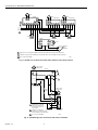
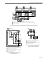
Fig. 10. L8124A,C single zone connections
and internal schematic.
CONTROLLER
CASE
IMMERSION
WELL CLAMP
ADAPTER
IMMERSION
WELL SPUD
BOILER
OLD IMMERSION
WELL ASSEMBLY
BACK OF
CONTROLLER
CASE
IMMERSION
WELL CLAMP
SCREW
ADAPTER
SENSING
BULB
HEAT-CONDUCTIVE COMPOUND
SETSCREW
CAPILLARY
TUBE
(C)
IMMERSION
WELL CLAMP
IMMERSION
WELL CLAMP SCREW
SHORT TUBE
FITS IN CENTRAL
RECESS OF ADAPTER
BEND THE CAPILLARY TUBE TO HOLD THE SENSING BULB IN GOOD THERMAL CONTACT WITH THE IMMERSION WELL AT POINTS (A) AND (B).
ASSURE THAT CAPILLARY TUBE FITS FREELY IN THE ADAPTER SO THE TENSION OF THE CAPILLARY TUBE AT POINT (C)
HOLDS THE SENSING BULB IN GOOD THERMAL CONTACT WITH THE IMMERSION WELL AT POINT (D).
M8830
1
1
2
2
(D)
(B)
(A)
M884
3
M8802
L1
(HOT)
L2
1
1
2
2
POWER SUPPLY. PROVIDE DISCONNECT MEANS AND
OVERLOAD PROTECTION AS REQUIRED.
CONTROL CASE MUST BE CONNECTED TO EARTH GROUND.
USE GROUNDING SCREW PROVIDED.
B1 IS 1/4 IN. TAB TERMINAL.
LINE VOLTAG
E
OIL BURNER
RELAY OR
GAS VALVE
LINE VOLTAGE
CIRCULATOR
C2
C1
B2
B1
R
B
HIGH
LIMIT
ZC
ZR
1K1
B
R
W
LOW LIMIT/
CIRCULATOR
1K
2
1
G
T
T
L8124A,C
LOW VOLTAGE
THERMOSTAT
1K2
3
3

L8124A,B,C,E,G,L,M AQUASTAT® RELAYS
60-2061—10 8
Fig. 11. L8124A in an oil-fired, forced hot water, tankless, zoned, pump system.
Fig. 12. L8124B single zone connections and internal schematic.
L1
(HOT)
L2
1
2
3
POWER SUPPLY. PROVIDE DISCONNECT MEANS AND OVERLOAD PROTECTION AS REQUIRED.
CONTROL CASE MUST BE CONNECTED TO EARTH GROUND. USE GROUNDING SCREW PROVIDED.
B1 IS 1/4 IN. TAB TERMINAL.
TT
L2
L1
C1
C2 B2
ZR
ZC
B1
M8822
3
2
BURNER
AND
IGNITION
L8124A
G
T
T
F
F
T87F
TT
1
2
3
45
6
T87F
R845 RELAY
R8184
TT
1
2
3
45
6
T87F
R845 RELAY
PUMP
PUMP
PUMP
BLACK
WHITE
ORANGE
C554
1
M8842
L1
(HOT)
L2
1
3
1
2
2
POWER SUPPLY. PROVIDE
DISCONNECT MEANS AND
OVERLOAD PROTECTION
AS REQUIRED.
CONTROL CASE MUST BE
CONNECTED TO EARTH GROUND.
USE GROUNDING SCREW PROVIDED.
B1 IS 1/4 IN. TAB TERMINAL.
MILLIVOLTAG
E
GAS VALVE
LINE VOLTAGE
CIRCULATOR
C2
C1
B2
B1
TH
TH
PP
PP
R
B
HIGH
LIMIT
1K1
B
R
W
LOW LIMIT/
CIRCULATOR
1K
2
1
G
T
T
L8124B
LOW VOLTAGE
THERMOSTAT
1K3
1K2
POWERPILE®
3

L8124A,B,C,E,G,L,M AQUASTAT® RELAYS
9 60-2061—10
Fig. 13. L8124B in a gas-fired, millivolt, forced hot water, tankless, zoned, pump system.
Fig. 14. L8124E single zone connections
and internal schematic.
Fig. 15. L8124E in a 24V, gas-fired
forced hot water, tankless system.
L
1
(
HOT)
L2
1
2
3
POWER SUPPLY. PROVIDE DISCONNECT MEANS AND OVERLOAD PROTECTION AS REQUIRED.
CONTROL CASE MUST BE CONNECTED TO EARTH GROUND. USE GROUNDING SCREW PROVIDED.
B1 IS 1/4 IN. TAB TERMINAL.
TT
1
2
3
45
6
M8841
THPP
1
2
3
TR
PP
MILLIVOLTAGE
GAS VALVE
(eg, VS820)
Q313A
PILOT
GENERATOR
L8124E
G
L2 L1
C1 C2
TT
B2 B1
T87F
R845 RELAY
TT
1
2
3
45
6
T87F
R845 RELAY
TT
1
2
3
45
6
T87F
R845 RELAY
PUMP PUMP PUMP
M8803
L1
(HOT)
L2
1
3
1
2
3
2
POWER SUPPLY. PROVIDE DISCONNECT MEANS AND
OVERLOAD PROTECTION AS REQUIRED.
CONTROL CASE MUST BE CONNECTED TO EARTH GROUND.
USE GROUNDING SCREW PROVIDED.
B1 IS 1/4 IN. TAB TERMINAL.
LOW VOLTAGE
GAS VALVE
(eg, VR8300)
LINE VOLTAG
E
CIRCULATOR
C2
C1
B2
B1
R
B
HIGH
LIMIT
Z
1K1
B
R
W
LOW LIMIT/
CIRCULATOR
1K
2
1
G
T
TV
L8124E
LOW VOLTAGE
THERMOSTAT
1K2
TR
TH
L1
(HOT)
L2
1
2
3
2
3
1
TH
TR
LOW VOLTAGE
GAS VALVE
(eg, VR8300)
L8124E
G
L2 L1
C1 C2
TT
B2 B1
T87F
POWER SUPPLY. PROVIDE DISCONNECT MEANS AND
OVERLOAD PROTECTION AS REQUIRED.
CONTROL CASE MUST BE CONNECTED TO EARTH GROUND
.
USE GROUNDING SCREW PROVIDED.
B1 IS 1/4 IN. TAB TERMINAL.
CIRCULATOR
M1796A

L8124A,B,C,E,G,L,M AQUASTAT® RELAYS
60-2061—10 10
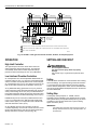
Fig. 16. L8124E in a 24V, gas-fired forced hot water, tankless, zoned pump system.
OPERATION
High Limit Controller
The high limit opens and turns off the burner when the
water temperature reaches the set point. The high limit
automatically resets after the water temperature drops
past the set point and through the 10°F (6°C) differential.
Low Limit and Circulator Controllers
On a temperature rise, with the adjustable differential at the
minimum setting of 10°F (°C), the burner circuit (R-B) breaks
and the circulator circuit (R-W) makes at the control set point.
On a temperature drop of 10° F (6°C) below the set point, the
R-B circuit makes and the R-W circuit breaks. See Fig. 22.
At any differential setting greater than 10°F (6°C), the R-B
make temperature and R-W break temperature will remain the
same (control setting minus 10°F (6°C). The R-B break and
R-W make temperature will be the set point temperature plus
the difference between the differential setting and 10°F (6°C).
EXAMPLE:Set point of 140°F (60°C) differential set at 25°F
(14°C). On a temperature rise, R-B will break and R-W will
make at 155°F (68°C). On a temperature fall, R-B will make
and R-W will break at 130°F (54°C).
On the L8124M, the burner and circulator circuits are
controlled separately—the low limit controls the burner circuit
(R-B) as described above, while the low voltage thermostat
directly controls the circulator circuit (see Fig. 18).
SETTING AND CHECKOUT
WARNING
Fire or Explosion Hazard.
Can cause severe injury, death or property
damage.
Use product only in a system with a pressure relief
valve.
Setting
Follow the boiler manufacturer recommendation when making
the L8124 settings. The high limit setting must be at least 20°F
(11°C) higher than the low limit setting. Place the indicators
over the selected temperature marks. The low limit differential
is set by turning the differential adjustment knob to the desired
amount of differential.
Setting Stop
A setting stop (Honeywell part no. 126580, ordered
separately) may be installed on the adjusting knob to prevent
turning the knob beyond a predetermined point. Fig. 23 shows
it installed on the high limit switch knob to prevent setting
higher than 200°F (93°C).
IMPORTANT
The setting stop cannot be reset once it is in place. If
the stop must be removed, snip it off with cutters; do
not twist it off.
L
1
(
HOT)
L2
1
2
3
POWER SUPPLY. PROVIDE DISCONNECT MEANS AND OVERLOAD PROTECTION AS REQUIRED.
CONTROL CASE MUST BE CONNECTED TO EARTH GROUND. USE GROUNDING SCREW PROVIDED.
B1 IS 1/4 IN. TAB TERMINAL.
TT
1
2
3
45
6
M1794A
TH
1
2
3
TR
LOW VOLTAGE
GAS VALVE
(eg, VR8300)
L8124E
AQUASTAT
®
RELAY
G
L2 L1
C1 C2
TT
B2 B1
T87F
R845 RELAY
TT
1
2
3
45
6
T87F
R845 RELAY
TT
1
2
3
45
6
T87F
R845 RELAY
PUMP PUMP PUMP

L8124A,B,C,E,G,L,M AQUASTAT® RELAYS
11 60-2061—10
Fig. 17. L8124G,L multizone system with zone
valve connections and internal schematic.
Fig. 18. L8124M single zone connections
and internal schematic.
M1795B
L1
(HOT)
L2
1
1
2
3
4
3
2
4
POWER SUPPLY. PROVIDE DISCONNECT MEANS AND
OVERLOAD PROTECTION AS REQUIRED.
UP TO TWO V8043F ZONE VALVES CAN BE POWERED WITH
L8124G,L. ADD ADDITIONAL TRANSFORMER FOR EVERY
TWO OR LESS VALVES.
CONTROL CASE MUST BE CONNECTED TO EARTH GROUND.
USE GROUNDING SCREW PROVIDED.
B1 IS 1/4 IN. TAB TERMINAL.
LINE VOLTAG
E
OIL BURNER
RELAY OR
GAS VALVE
LINE VOLTAG
E
CIRCULATOR
B2
C2
C1
ZR
B1R
B
HIGH
LIMIT
Z
1K1
B
R
W
LOW LIMIT/
CIRCULATOR
1K
2
1
G
T
TV
L8124G,L
ZONE 1
THERMOSTAT
1K2
V8043F
TH
TR
TH
TR
ZONE 2
THERMOSTAT
V8043F
TH
TR
TH
TR
ZC
M8804
L1
(HOT)
L2
1
3
1
2
3
2
POWER SUPPLY. PROVIDE DISCONNECT MEANS
AND OVERLOAD PROTECTION AS REQUIRED.
CONTROL CASE MUST BE CONNECTED TO EARTH
GROUND. USE GROUNDING SCREW PROVIDED.
B1 IS 1/4 IN. TAB TERMINAL.
LINE VOLTAG
E
OIL BURNER
RELAY OR
GAS VALVE
LINE VOLTAG
E
CIRCULATOR
C2
C1
B2
B1
R
B
HIGH
LIMIT
ZC
1K1
B
R
W
LOW LIMIT
1K
L2
L1
G
TT
L8124M
LOW VOLTAGE
THERMOSTAT

L8124A,B,C,E,G,L,M AQUASTAT® RELAYS
60-2061—10 12
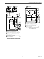
Fig. 19. L8124A,C multizone system with circulator connections and internal schematic.
Fig. 20. L8124E multizone system with circulator connections and internal schematic.
M8827
L1
(HOT)
L2
1
1
2
3
2
3
POWER SUPPLY. PROVIDE DISCONNECT MEANS AND
OVERLOAD PROTECTION AS REQUIRED.
CONTROL CASE MUST BE CONNECTED TO EARTH
GROUND. USE GROUNDING SCREW PROVIDED.
B1 IS 1/4 IN. TAB TERMINAL.
LINE VOLTAGE
OIL BURNER
RELAY OR
GAS VALVE
LINE VOLTAGE
CIRCULATOR
C2
C1
B2
B1
R
B
HIGH
LIMIT
ZC
ZR
1K1
B
R
W
LOW LIMIT/
CIRCULATOR
1K
2
2
1
4
3
5
6
1
G
T
T
L8124A,C
LOW VOLTAGE
THERMOSTAT
1K2
ZONE 2
LOW VOLTAGE
THERMOSTAT
R845A RELAY ZONE 2
ZONE 2
CIRCULATO
R
TO ADDITIONAL
R845A RELAYS
FOR OTHER ZONES
M8828
L1
(HOT)
L2
1
1
2
3
POWER SUPPLY. PROVIDE DISCONNECT MEANS AND
OVERLOAD PROTECTION AS REQUIRED.
CONTROL CASE MUST BE CONNECTED TO EARTH
GROUND. USE GROUNDING SCREW PROVIDED.
B1 IS 1/4 IN. TAB TERMINAL.
2
1
4
3
5
6
ZONE 1
LOW VOLTAG
E
THERMOSTAT
R845A RELAY ZONE 1
ZONE 1
CIRCULATOR
TO ADDITIONAL
R845A RELAYS
FOR OTHER ZONES
2
3
LOW VOLTAGE
GAS VALVE (eg, VR8300)
C2
C1
B2
B1
R
B
HIGH
LIMIT
Z
1K1
B
R
W
LOW LIMIT/
CIRCULATOR
1K
2
1
G
T
TV
L8124E
1K2
TR
TH
THTR

L8124A,B,C,E,G,L,M AQUASTAT® RELAYS
13 60-2061—10
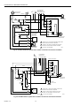
Fig. 21. L8124L multizone system with circulator connections and internal schematic.
To install the setting stop:
1. Turn the knob to the setting that is to be established as
the limit.
2. Place the setting stop over the knob in the position
where the arm of the setting stop strikes (after the stop
is pressed into place) projection A and prevents turning
the knob beyond the desired limit setting.
3. Press the setting stop tightly onto the knob so its inner
teeth securely engage the knob.
4. Turn the knob back and forth several times to make
sure the stop functions properly.
5. n all the settings are made, replace the cover.
Fig. 22. Relationship of set points and differential.
M882
9
L1
(HOT)
L2
1
3
1
2
3
2
POWER SUPPLY. PROVIDE DISCONNECT MEANS AND
OVERLOAD PROTECTION AS REQUIRED.
CONTROL CASE MUST BE CONNECTED TO EARTH
GROUND. USE GROUNDING SCREW PROVIDED.
B1 IS 1/4 IN. TAB TERMINAL.
2
1
4
3
5
6
LOW VOLTAGE
THERMOSTAT
ZONE 1
ZONE 2
LOW VOLTAGE
THERMOSTAT
R845A RELAY ZONE 2
ZONE 2
CIRCULATO
R
TO ADDITIONAL
R845A RELAYS
FOR OTHER ZONES
LINE VOLTAGE
OIL BURNER
RELAY OR
GAS VALVE
LINE VOLTAGE
CIRCULATOR
ZONE 1
B2
C2
C1
ZR
B1R
B
HIGH
LIMIT
Z
1K1
B
R
W
LOW LIMIT/
CIRCULATOR
1K
2
1
G
T
TV
L8124L
1K2
ZC
LOW LIMIT
AND
CIRCULATOR
SETTING
H
IGH LIMIT
S
ETTING
SWITCH BREAKS ON
TEMPERATURE RISE.
BURNER TURNS OFF.
CIRCULATOR OPERATES
ON A CALL FOR HEAT.
SWITCH MAKES ON
TEMPERATURE FALL.
BURNER OPERATES ON
A
CALL FOR HEAT.
SWITCH MAKES R-W
AND BREAKS R-B ON
TEMPERATURE RISE.
SWITCH MAKES R-B AND
BREAKS R-W ON
TEMPERATURE FALL.
BURNER IS ON TO
MAINTAIN MINIMUM
WATER TEMPERATURE.
CIRCULATOR IS OFF.
M1523
SWITCH MAKES R-W
AND BREAKS R-B ON
TEMPERATURE RISE.
WHEN WATER REACHES PROPER TEMPERATURE, THE BURNER
SHUTS OFF OR THE CIRCULATOR PUMP STARTS (WHEN CALLING
FOR HEAT).
1
1

L8124A,B,C,E,G,L,M AQUASTAT® RELAYS
60-2061—10 14
Fig. 23. Setting stop in position to limit
the high limit setting to 200°F (93°C).
Heat Anticipator
The thermostat heat anticipator should be set at 0.2A.
CHECKOUT
Put the system into operation and observe each function
through at least one complete cycle. Be sure the control
operates as intended.
Material Safety Data Sheet (MSDS) for heat-conductive
compound, which is included with TRADELINE Aquastat
Relay models.
MATERIAL SAFETY DATA SHEET
(MSDS)
SECTION 1. PRODUCT AND
COMPANY IDENTIFICATION.
Product Name: Heat conductive compound.
MSDS ID: DS9021.
Synonyms: MS1699.
Product Use: Heat conductive material used to enhance
contact and heat transfer in temperature sensor applications.
Manufacturer: Honeywell Inc., 1985 Douglas Drive North,
Minneapolis, MN 55422.
Date Released: October 8, 1999.
NFPA Ratings:
Health 0; Flammability 1; Reactivity 0;
Personal Protection B.
220
200
160
140
180
SETTING STOP
SETTING
STOP ARM
P
ROJECTION "A"
KNOB SET AT 180°F (82°C)
M2844
1
1
SCALE MARKINGS IN FAHRENHEIT ONLY.

L8124A,B,C,E,G,L,M AQUASTAT® RELAYS
15 60-2061—10
Section 2. Composition, Information
on Ingredients (Table 3).
Table 3. Ingredients of Heat Conductive Compound
a
.
a
Additional Information: Part No. 120650 (0.5 oz. tube); Part No. 107408 (4 oz. can); Part number 197007 (5 gallon container).
May also contain minute amounts of lithium and molybdenum lubricant compounds.
Section 3. Hazard Identification
Acute Health Effects:
Skin—Excessive contact can cause skin irritation
and dermatitis.
Eye—Direct contact with eye will cause irritation.
Inhalation—No adverse effects are expected.
Ingestion—Ingestion of product may cause nausea, vomiting
and diarrhea.
Chronic Health Effects:
Existing skin rash or dermatitis may be aggravated by
repeated contact.
OSHA Hazard Classifications:
None.
Carcinogenicity:
Not considered to be a carcinogen by either OSHA, NTP,
IARC, or ACGIH.
Target Organs:
None known.
Section 4. First Aid Measures
Eye Contact:
Flush eyes with water for 15 minutes. Remove any contact
lenses and continue to flush. Obtain medical attention if
irritation develops and persists.
Skin Contact:
Remove excess with cloth or paper. Wash thoroughly with
mild soap and water. Obtain medical attention if irritation
develops and persists.
Ingestion:
Contact physician or local poison control center immediately.
Inhalation:
Remove patient to fresh air and obtain medical attention if
symptoms develop.
Section 5. Fire Fighting Measures
Flash Point:
>383°F (195°C). Will burn if exposed to flame.
Extinguishing Media:
Carbon dioxide, dry chemical or foam.
Special Fire Fighting Procedures:
None.
Explosion Hazards:
None. Aluminum powder can react with water to release
flammable hydrogen gas. In the form of this product, this
reaction is not expected.
Section 6. Accidental Release Measures
Scrape up and dispose as solid waste in accordance with
state and federal regulations.
Ingredients CAS Number Percent PEL TLV
No. 2 Lithium Complex Grease (70%):
Mineral Oil 64742-65-0 35-50
5 mg/m
3
5 mg/m
3
Mineral Oil 64742-62-7 20-25
5 mg/m
3
5 mg/m
3
Lithium Hydrostearate/Sebacate Complex 68815-49-6 4-9 — —
Zinc Alkyldithiophosphate 68649-42-3 0-2 — —
Aluminum Paste (30%):
Aluminum, as Al 7429-90-5 20-25
15 mg/m
3
10 mg/m
3
Aliphatic Petroleum Distillates 8052-41-3 10-15
2900 mg/m
3
525 mg/m
3
Stearic Acid 57-11-4 1-2 — —
Aromatic Petroleum Distillates 64742-95-6 1-2
5 mg/m
3
5 mg/m
3

60-2061—10 G.R. Rev. 12-01 www.honeywell.com
Automation and Control Solutions Automation and Control Solutions
Honeywell Honeywell Limited-Honeywell Limitée
1985 Douglas Drive North 35 Dynamic Drive
Golden Valley, MN 55422 Scarborough, Ontario
M1V 4Z9
Printed in U.S.A. on recycled
paper containing at least 10%
post-consumer paper fibers.
L8124A,B,C,E,G,L,M AQUASTAT® RELAYS
Section 7. Handling and Storage
Store in dry place. Keep container closed when not in use.
Section 8. Exposure Controls
and Personal Protection
Ventilation:
No special ventilation is required when working with this
product.
Respiratory Protection:
None required.
Eye Protection:
Not normally required. However, use chemical safety goggles
or faceshield if potential for eye contact exists, especially if
material is heated.
Hand/Clothing Protection:
Not normally required. Protective gloves and clothing are
recommended, as material is difficult to remove from skin and
clothing.
Other Protective Equipment:
None required.
Section 9. Physical and Chemical Properties
Appearance/Odor:
Aluminum color, semi-solid material, pleasant odor.
Solubility in Water:
Negligible.
Specific Gravity:
0.86.
Section 10. Stability and Reactivity
Stability:
Stable.
Reactivity:
Hazardous polymerization will not occur.
Incompatibilities:
Strong oxidizing agents and halogens.
Hazardous Decomposition Products:
Carbon dioxide, carbon monoxide.
Section 11. Toxicology Information
No data available.
Section 12. Ecological Information
Chemical Fate Information:
Hydrocarbon components will biodegrade in soil; relatively
persistent in water.
Section 13. Disposal Consideration
Dispose of as solid waste in accordance with Local, State and
Federal regulations.
Section 14. Transportation Information
DOT Classification:
Not classified as hazardous.
Section 15. Regulatory Information
SARA Title III Supplier Notification:
Include in Section 311/312 inventory reports if amounts
exceed 10,000 pounds. Aluminum compounds are subject to
the reporting requirements under Section 313 of Emergency
Planning and Community Right-to-Know Act of 1986 (40 CFR
372). Ingredients listed in TSCA Inventory.
Section 16. Other Information
This information is furnished without warranty, expressed or
implied, except that it is accurate to the best of our knowledge.
Prepared By:
PROSAR, 1295 Bandana Boulevard, Suite 335, St. Paul, MN
55108 (651-917-6100).
-
 1
1
-
 2
2
-
 3
3
-
 4
4
-
 5
5
-
 6
6
-
 7
7
-
 8
8
-
 9
9
-
 10
10
-
 11
11
-
 12
12
-
 13
13
-
 14
14
-
 15
15
-
 16
16


Ask a question and I''ll find the answer in the document
Finding information in a document is now easier with AI
Related papers
-
Honeywell AQUASTAT L8124A User manual
-
resideo VR8345H4555 User manual
-
Unbranded L8148A User manual
-
resideo Aquastat L8148A Operating instructions
-
-
resideo L7224U1002 Installation guide
-
-
resideo L6081A User manual
-
-
resideo L4103A,B,C COMBINATION AQUASTAT AND HIGH LIMIT CONTROLLER User guide
Other documents
-
-
-
-
White Rodgers 11B02-1 User manual
-
-
-
Sansaire SA15 User manual
-
ClimateMaster ATM11H05S and ASUB05 Install Manual
-
 Armstrong Pumps 110123120 Installation guide
-
Honeywell T87F DESIGNER User manual
