resideo L6081A User manual

Type
User manual

The resideo L6081A Aquastat Controller is a triple function controller capable of replacing over 20 different controls from several manufacturers, including Honeywell, White Rodgers, and Mercoid. It can be used as a high limit, low limit, and circulator control and features an adjustable differential of 10-60°F (6-32°C). The L6081A's high limit function automatically resets after the water temperature drops past the setpoint and through the differential. Its low limit and circulator controls allow for precise temperature regulation and can be set to operate on a call for heat.

The resideo L6081A Aquastat Controller is a triple function controller capable of replacing over 20 different controls from several manufacturers, including Honeywell, White Rodgers, and Mercoid. It can be used as a high limit, low limit, and circulator control and features an adjustable differential of 10-60°F (6-32°C). The L6081A's high limit function automatically resets after the water temperature drops past the setpoint and through the differential. Its low limit and circulator controls allow for precise temperature regulation and can be set to operate on a call for heat.

INSTALLATION INSTRUCTIONS
95-6701-07
L6081A Aquastat® Controller
APPLICATION
The L6081A is a triple function controller; it is used as a
high limit, low limit, and circulator control. This
controller is designed to replace the controls listed in
Table 1. When replacing some of these controls, only 1
or 2 of the L6081A switching functions may be needed.
Refer to Fig. 2 to determine which terminals are used in
a given application.
Table 1. Controls L6081A Replaces.
aAll require a 124904 Well Adapter to fit L6081A case to well (order separately, see form 68-0040, Wells and Fittings
for Temperature Controllers).
bWell for L6081A must be added when replacing these models.
INSTALLATION
When Installing This Product…
1. Read these instructions carefully. Failure to follow
them could damage the product or cause a
hazardous condition.
2. Check the ratings given in the instructions and on
the product to make sure the product is suitable
for your application.
3. Installer must be a trained, experienced service
technician.
4. After installation is complete, check out product
operation as provided in these instructions. For
MSDS information on heat-conductive compound,
visit customer.resideo.com.
WARNING
Explosion Hazard.
Can cause serious injury, death or property
damage.
Use this product only in systems with pressure
relief valves.
WARNING
Electrical Shock Hazard.
Can cause serious injury or death.
Disconnect power supply before installation to
prevent electrical shock or equipment damage.
NOTE: If new immersion well is needed, refer to form
68-0040 Wells and Fittings for Temperature
Controllers for ordering information.
Mounting
Follow the mounting system manufacturer instructions
if available; otherwise, proceed as follows:
1. Turn off power and drain the system if necessary.
2. Remove old control.
3. loosen the captive cover mounting screw on the
L6081A and pull off the cover.
IMPORTANT:
Best thermal response is obtained with a well
that snugly fits the sensing bulb.
If well does not snugly fit bulb, use the
heat-conductive grease. Fold the plastic bag of
grease lengthwise and twist it gently. Then snip
off end of bag and work the open end all the
way into the well. Slowly pull out bag while
squeezing it firmly to distribute grease evenly
in the well. Insert bulb all the way to the bottom
of the well. Bend the tubing, if necessary, to
hold the bulb against the bottom of the well
and to hold the outer end of the bulb in firmly to
the side of the well (Fig. 1). Wipe excess grease
off outer end of the well.
Resideo General ControlsaMercoidaPennaWhite Rodgersa
L401A
L4010B
L4062A
L4062B
L4081A,B
L6062A
L6081A,C
L52F
L52G
L52H
L52J
L52K
L52L
480
DA-36-153 443ATb 4432
447G 4432X
4420 4433
4420X 4433X
4422 4436
4422X 4437
11A61b
11C61
1131b
1135
11C30
1115
11C31
L6081A AQUASTAT® CONTROLLER
95-6701—07 2
4. Loosen the insertion well clamp screw (Fig. 1).
5. If the immersion well from the old control fits into
the clamp on the back of the L6081 case, proceed
as follows. If it does not, go to step 6 below.
a. Apply heat-conductive grease as instructed
above.
b. Insert the sensing element into the well.
c. Fasten the case to the well with the clamp
screw. Make certain that the clamp is properly
positioned on the well and the well flange fits
snugly into the opening in the case. The
sensing element bulb must bottom in the well
for best temperature response. (A slight bend
in the tubing holds the bulb against the well.)
See Fig. 1.
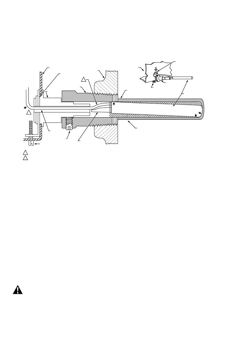
Fig. 1. Use of adapter and proper position of sensing bulb in immersion well.
6. If the immersion well from the old control does not
fit into the clamp on the back of L6081A case, use
the 124904 Well Adapter (order separately, see
form 68-0040, Wells and Fittings for Temperature
Controllers).
a. Fit sensing element capillary into the adapter
groove (Fig. 1).
b. Fasten the adapter to the case. Make certain
that the clamp is properly positioned on the
adapter and the adapter flange fits snugly into
the opening in the case.
c. Apply heat-conductive grease as instructed
above.
d. Insert the bulb and adapter into the well. The
sensing element bulb must bottom in the well
for best temperature response. (A slight bend
in the tubing will hold the bulb against the well.)
See Fig. 1.
e. Tighten the setscrew. Make certain that the
adapter groove is on the opposite side of the
setscrew (Fig. 1).
WIRING
WARNING
Electrical Shock Hazard.
Can cause serious injury, death or property
damage.
Disconnect power supply to prevent electrical
shock or equipment damage.
All wiring must comply with local electrical codes. Make
certain that the electrical requirement of the controlled
equipment does not exceed the rating shown inside the
L6081A cover. Follow the hookup instructions furnished
by the system manufacturer.
IMPORTANT:
L6081A terminals are approved for copper wire
only.
Use Fig. 2 to determine which switches to use when
replacing the existing control. For example, if the existing
control has high limit and circulator control switch
terminals, use terminals R and B on the left side of the
switch for the high limit and the R and W terminals on the
right side of the switch to control the circulator.
Fig. 3 shows a typical L6081A hookup.
NOTE: If the 128975 Field Addable Jumper (included) is
used (Fig. 2 and 3), make sure that the two
prongs of the jumper face the center of the
controller.
OPERATION AND SETTING
High Limit
The high limit opens and turns off the burner when the
water temperature reaches the setpoint. The high limit
automatically resets after the water temperature drops
past the setpoint and through the 10°F (6°C) differential.
CONTROLLER
CASE IMMERSION
WELL CLAMP
ADAPTER
IMMERSION
WELL SPUD
BOILER
OLD IMMERSION
WELL ASSEMBLY
BACK OF
CONTROLLER
CASE
IMMERSION
WELL CLAMP
SCREW
ADAPTER
SENSING
BULB
HEAT-CONDUCTIVE COMPOUND
SETSCREW
CAPILLARY
TUBE
(C)
IMMERSION
WELL CLAMP
IMMERSION
WELL CLAMP SCREW
SHORT TUBE
FITS IN CENTRAL
RECESS OF ADAPTER
BEND THE CAPILLARY TUBE TO HOLD THE SENSING BULB IN GOOD THERMAL CONTACT WITH THE IMMERSION WELL AT POINTS (A) AND (B).
ASSURE THAT CAPILLARY TUBE FITS FREELY IN THE ADAPTER SO THE TENSION OF THE CAPILLARY TUBE AT POINT (C)
HOLDS THE SENSING BULB IN GOOD THERMAL CONTACT WITH THE IMMERSION WELL AT POINT (D).
M8830
1
1
2
2(D)
(B)
(A)
L6081A AQUASTAT® CONTROLLER
395-6701—07
Fig. 2. Internal wiring of L6081A.
Fig. 3. Typical L6081A hookup.
WARNING
Explosion Hazard.
Can cause severe injury, death or property
damage.
Use this product only in systems with a pressure
relief valve.
Low Limit and Circulator Controls
On a temperature rise, with the adjustable differential at
the minimum setting of 10°F (6°C), the burner circuit
R-B breaks and the circulator control R-W makes at the
control setpoint. On a temperature drop of 10°F (6°C)
below the setpoint, the R-B circuit makes and the R-W
circuit breaks.
At any differential setting greater than 10°F (6°C), the
R-B make temperature and R-W break temperature
remain the same (control setting minus 10°F [6°C]). The
R-B break and R-W make temperature are the setpoint
temperature plus the difference between the differential
setting and 10°F (6°C). Fig. 4. Internal view of L6081A.
M8874A
1
2
3
33
1
2
MAKES R-B, BREAKS R-W ON TEMPERATURE FALL.
BREAKS ON TEMPERATURE RISE.
B TERMINALS ARE TAB TERMINALS.
B
R
W
B
RJUMPER
HIGH LIMIT LOW LIMIT/CIRCULATOR
M8855
L1
(HOT)
L2 1
2
1
2
POWER SUPPLY. PROVIDE DISCONNECT
MEANS AND OVERLOAD PROTECTION
AS REQUIRED.
B TERMINALS ARE TAB TERMINALS.
SOLID
STATE
SWITCH SAFETY
SWITCH
HEATER
B
2 4 3 1 B
RR
W
BURNER MOTOR
OIL VALVE
IGNITION
SS
1K 1K2
1K1
F
F
T
T
R4184D PROTECTORELAY™ CONTROL JUNCTION BOX
BLACK
ORANGE
WHITE
CIRCULATOR
L6081A JUMPER
ADDED
24V
THERMOSTAT
1R
1R1
RA89A SWITCHING RELAY
CAD
CELL
M8848A
WELL CLAMP
SCREW
STRIP
GAUGE
LOW LIMIT/
CIRCULATOR
DIFFERENTIAL
ADJUSTMENT
LOW LIMIT
SETPOINT
ADJUSTMENT
JUMPER
SLOT
HIGH LIMIT
SETPOINT
ADJUSTMENT
L6081A AQUASTAT® CONTROLLER
© 2020 Resideo Technologies, Inc. All rights reserved.
This product is manufactured by Resideo Technologies, Inc. and its affiliates.
www.resideo.com
Resideo Technologies, Inc.
1985 Douglas Drive North, Golden Valley, MN 55422
1-800-468-1502
95-6701—07 M.S. Rev. 12-21 | Printed in United States
At any differential setting greater than 10°F (6°C), the
R-B make temperature and R-W break temperature
remain the same (control setting minus 10°F [6°C]). The
R-B break and R-W make temperature are the setpoint
temperature plus the difference between the differential
setting and 10°F (6°C).
Example: Setpoint of 140°F (60°C); differential set at
25°F (14°C). On a temperature rise, R-B breaks and
R-W makes at 155°F (69°C). On a temperature fall, R-B
makes and R-W breaks at 130°F (55°C).
Setting Stop
The 126580 Setting Stop may be installed on the
adjusting knob to prevent turning the knob beyond a
predetermined point. Fig. 6 shows the stop installed on
the knob of a high limit switch at a setpoint of 180°F
(82°C). To install the setting stop, proceed as follows:
1. Turn the knob to the setting that is to be estab-
lished as the limit.
2. Place the setting stop over the knob in position so
the arm of the setting stop (after stop is pressed
into place) strikes projection A and prevents
turning the knob beyond the desired limit setting.
IMPORTANT:
Be extremely careful when installing the setting
stop. It cannot be reset once it is in place. If the
stop must be removed, snip it off with cutters;
do not twist off.
3. Press setting stop tightly onto the knob so its
inner teeth engage the knob securely.
4. Turn the knob back and forth several times to
make sure the stop functions properly.
5. When all settings are made, replace the cover.
Fig. 5. Relationship of setpoints and differential
adjustments.
Fig. 6. Setting stop installed to prevent turning high limit
setting beyond 180°F (82°C).
CHECKOUT
Put system into operation. Carefully observe the
operation of all components for at least one complete
cycle.
LOW LIMIT
AND
CIRCULATOR
SETTING
HIGH LIMIT
SETTING
SWITCH BREAKS ON
RISE. BURNER TURNS OFF.
CIRCULATOR OPERATES
ON A CALL FOR HEAT.
SWITCH MAKES ON
FALL. BURNER
OPERATES ON A
CALL FOR HEAT.
SWITCH MAKES R-W
AND BREAKS R-B ON
RISE. 10°F (6°C)
DIFFERENTIAL.
SWITCH MAKES R-B AND
BREAKS R-W ON
FALL. BURNER IS ON;
CIRCULATOR IS OFF.
110°F (43°C)
240°F (116°C)
M8875
SWITCH MAKES R-W
AND BREAKS R-B ON
RISE. 25°F (14°C)
DIFFERENTIAL.
10°F (6°C)
DIFFERENTIAL
25°F (14°C)
DIFFERENTIAL
10°F (6°C)
DIFFERENTIAL
L6081A,C
220
200
160
140
180
SETTING STOP
SETTING
STOP ARM
PROJECTION "A"
KNOB SET AT 180°F (82°C)
M2844
1
1
SCALE MARKINGS IN FAHRENHEIT ONLY.
  • Page 1 1
  • Page 2 2
  • Page 3 3
  • Page 4 4

resideo L6081A User manual

Type
User manual

The resideo L6081A Aquastat Controller is a triple function controller capable of replacing over 20 different controls from several manufacturers, including Honeywell, White Rodgers, and Mercoid. It can be used as a high limit, low limit, and circulator control and features an adjustable differential of 10-60°F (6-32°C). The L6081A's high limit function automatically resets after the water temperature drops past the setpoint and through the differential. Its low limit and circulator controls allow for precise temperature regulation and can be set to operate on a call for heat.

Ask a question and I''ll find the answer in the document

Finding information in a document is now easier with AI