Page is loading ...

Funktionsschaltbild
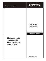
Function diagram
Schéma de fonctionnement
CONTROL UNIT
LOAD 1 LOAD 4LOAD 3
L+
OUT 1(+)
IN 4 (–) IN 2 (+)IN 3 (–) IN 1 (+)
OUT 4(+)OUT 3(+)
+
C/Q
–
L-
AC
DC
DC 24 V
LOAD 2
OUT 2(+)
MAX. 40 A
deutsch
Der elektronische Schutzschalter teilt den Laststrom auf mehrere 24-V-Abzweige auf
und überwacht sie zuverlässig auf Überlast und Kurzschluss. Kurz fristige Strom-
spitzen, z.B. durch einen hohen Einschaltstrom, lässt die Elektronik zu, Abzweige mit
längerer Überlast schaltet sie stromlos. Der Auslösestrom eines jeden Ausgangs
kann individuell mit einem von vorne zugänglichen Stromwahlschalter oder per IO-LINK
Schnittstelle eingestellt werden. Die Ausgänge werden zeitversetzt und lastabhängig
eingeschaltet, um Spitzeneinschaltströme zu verringern. Bei Überschreitung des
Nennstromes wird der Ausgang nach einer definierten Auslösezeit automatisch
abgeschaltet und kann nach einer kurzen Wartezeit (thermische Entspannung)
mittels Taster oder IO-LINK Schnittstelle wieder eingeschaltet werden. Der Taster
dient ebenfalls zum manuellen Abschalten des jeweiligen Ausgangs. Über die IO-LINK
Schnittstelle lassen sich betriebsrelevante Informationen auslesen als auch gezielt
einzelne Ausgänge ein- oder ausschalten. Über eine mehrfarbige LED wird der Status
des jeweiligen Ausgangs angezeigt.
Funktionsbeschreibung
Bitte lesen Sie diese Warnungen und Sicherheitshinweise sorgfältig durch, bevor Sie
das Gerät in Betrieb nehmen. Das Gerät darf nur durch fachkundiges und qualifiziertes
Personal installiert werden. Bei Funktionsstörungen oder Beschädigungen schal-
ten Sie sofort die Versorgungsspannung ab und senden das Gerät zur Überprüfung
ins Werk. Das Gerät beinhaltet keine Servicebauteile. Bei Auslösen einer internen
Sicherung liegt höchstwahrscheinlich ein interner Defekt am Gerät vor. Die angege-
benen Daten dienen allein der Produktbeschreibung und sind nicht als zugesicherte
Eigenschaften im Rechtssinne aufzufassen.
Bestimmungsgemäßer Gebrauch
Dieses Gerät ist für den Einbau in ein Gehäuse konzipiert und zur Ver wendung für allge-
meine elektronische Geräte, wie z.B. Industriesteuerungen, Bürogeräte, Kommunikati-
onsgeräte oder Messgeräte geeignet. Benutzen Sie dieses Gerät nicht in Steuerungs-
anlagen von Flugzeugen, Zügen oder nuklearen Einrichtungen, in denen eine Funktions-
störung zu schweren Verletzungen führen oder Lebensgefahr bedeuten kann.
Installation
Die Installation ist entsprechend den örtlichen Gegebenheiten, einschlägigen Vor-
schriften, nationalen Unfallverhütungsvorschriften und den anerkannten Regeln der
Technik durchzuführen. Dieses elektrische Betriebsmittel ist eine Komponente, die
zum Einbau in elektrische Anlagen oder Maschinen bestimmt ist und erfüllt die Anfor-
derungen der Niederspannungsrichtlinie (2014/35/EU). Der geforderte Mindestab-
stand zu benachbarten Teilen ist einzuhalten, um die Kühlung nicht zu behindern!
Vor Inbetriebnahme lesen
Bedienelemente
Fig. 1
1
2
3
4
5
6
Plombierbare Abdeckung der Stromwahlschalter
Eingang (+24 V und 0 V)
Der Anschluss 0V dient nur der Eigenversorgung des Schutzschalters.
Ausgänge zum Anschluss der Verbraucherkreise. Die 0 V der Verbraucher sind
über getrennte Leitungen direk t zur Stromversorgung zu führen.
Stromwahlschalter
Taster An/Aus/Reset mit integrierter LED
IO-LINK Schnittstelle
Betriebszustände,
Signalisierung, Reaktionen
1) Nach Abschluss der Modulinitialisierung werden die Ausgänge lastabhängig eingeschaltet.
2) Der Ausgang wird gemäß Auslösekennlinie automatisch abgeschaltet. Bei Abschaltung Übergang nach
Betriebszustand Z4.
3) Der Zust and jedes Ausgangs wir d beim Ausschal ten des Gerätes gespeichert.
4) Nach einer Wartezeit (thermische Entspannung) Übergang nach Betriebszustand Z 6. Beim Ausschalten
des Gerätes wird die restliche Wartezeit gespeichert und beim Wiedereinschalten abgewartet. Dadurch
wird auch bei sofortigem Wiedereinschalten des Gerätes eine Überlastung der Schaltelemente zuverlässig
verhindert.
5) Der betrof f ene Ausgang kann durch zweimaligen Tast endruck oder über einen Impuls über die IO-L INK
Schnittstelle wiedereingeschaltet werden, Übergang nach Betriebszustand Z1.
Betriebszustand / Beschreibung LED Taster wird gedrückt =>
Übergang nach...
Z 0 Modulinitialisierung 1) aus ---
Z 1 Ausgang eingeschaltet, Funktion OK grün Z 4
Z 2 Ausgangsstrom > 90 % vom Nennstrom grün
blinkend
Z 4
Z 3 Ausgangsstrom > Nennstrom 2) grün
blinkend
Z 4
Z 4 Ausgang ist manuell oder per Schnittstelle
abgeschaltet 3)
rot Z 1
Z 5 Ausgang ist aufgrund eines Überstroms abge-
schaltet, thermische Entspannung aktiv 4)
rot
blinkend
---
Z 6 Ausgang ist aufgrund eines Überstroms abge-
schaltet, thermische Entspannung ist beendet 5)
orange
blinkend
Z 4
Z 7 Gerätefehler (defekte Sicherung detektiert) rot schnell blinkend Z 4
Elektronischer Schutzschalter, Power Mini
Electronic circuit breaker, Power Mini
Disjoncteur électronique, Power Mini
1
2
3
4
5
6
ECONOMY SMART
PM-FU/DC24
français / english / deutsch
block.eu
BLOCK Transformatoren-Elektronik GmbH
Max-Planck-Straße 36-46 . 27283 Verden, Germany
info@block.eu . block.eu
#005-0292 24.10.2017
Prüfzeichen
Markings
Approbation
U o
UL 2367 UL 508

english français
The electronic circuit breaker distributes and monitors the load current over several
current circuits. Overloads and short circuits on an output are reliably recognized. The
electronics permit brie f current peaks and switch longer overloads of f. The rated cur -
rent for each output can be individually set with a current-selector-switch accessible
from the front or the IO-LINK interface. The outputs are time-delay and load-depend
activated to avoid overload current. If the rated current is exceeded for a certain time,
the output will be switched off automatically and can be switched on after a waiting
time (thermal relaxation) using the pushbutton or the IO-LINK interface. The pushbut-
ton can also be used to switch the output manually. It is possible to read out the state
of each output using the IO-LINK interface. The state of each output is also indicated
with a multi- colored LED.
Product Description
Le disjoncteur électronique permet la distribution du courant de charge sur plusieurs
sorties 24 V DC et les contrôle fiablement en cas de surcharge ou court- circuit. La
prot ec tion élec tronique autorise des pics de courant tel qu’un courant d’appel élevé au
démarrage. Elle se désactivera en cas de charges plus longues.
Le courant de déclenchement de chacune des sorties peut être paramétré
individuellement via les sélecteurs situés à l’avant de l’appareil ou à travers l’interface
IO- LINK. Les sorties sont activées avec un décalage en tenant compte des charges
afin d’éviter les pics de courant . En cas de dépassement du courant nominal, la
sortie sera automatiquement désactivée après un délai de déclenchement défini et
pourra après un bref temps d’att ente (détente thermique) être réactivée à l’aide
du bout on ou à travers l’inter face IO-LINK . L’inter face IO-LINK sert aussi pour la
désactivation manuelle des sor ties respectives. Il est possible de visualiser les ét ats
de fonctionnement via les sorties de signalisation, ainsi que d’activer ou désactiver
individuellement les sorties. L’état des sorties sera indiqué individuellement par une
LED multicolore.
Fonctionnement général
Before operating this unit please read the manual thoroughly. This device may only be
installed and put into operation by qualified personnel. If damage or malfunction should
occur during operation, immediately turn power off and send unit to the factory for
inspection. The unit does not contain serviceable parts. The tripping of an internal fuse
is caused by an internal defect.
The information presented in this document is believed to be accurate and reliable and
may change without notice.
Intendend Use
This device is designed for installation in an enclosure and is intended for general use
such as in industrial control, office, communication, and instrumentation equipment.
Do not use this device in aircraft, trains and nuclear equipment where malfunction may
cause severe personal injury or threaten human life
Installation
Installation must be carried out according to the prevailing local conditions and safety
regulations, national accident prevention regulations and the generally accepted rules
of technology. This equipment is a component designed for installation into electrical
systems and machines, and fulfills the requirements of the low voltage guidelines
(2014/35/EU). The required minimum spacing to neighboring components must be
observed to guarant ee the required cooling!
Read this first
Veuillez lire soigneusement ces avertissements et consignes de sécurité avant de
mettre l’appareil en service. L’appareil ne doit être installé que par du personnel
compétent et qualifié. En cas de dysfonctionnement, couper immédiatement la tension
d’alimentation et retourner l’appareil à l’usine pour vérification. L’appareil ne contient
pas de pièces échangeables. En cas de déclenchement d’un fusible interne, l’appareil
présente vraisemblablement un défaut. Les données indiquées sont à but descriptif.
Elles ne doivent pas être interprétées comme des caractéristiques assurées au sens
juridique du terme.
Usage conforme
Cet appareil est conçu pour être installé en armoire et convient à une utilisation sur
des installations électriques générales telles que des commandes industrielles, des
appareils de bureau, de communication ou de mesure. Ne pas utiliser cet appareil à
bord des commandes d’avions, de trains, ou installations nucléaires, dans lesquelles un
dysfonctionnement peut entrainer des blessures graves ou signifier un risque mortel
Installation
L’installation doit être réalisée conformément aux recommandations locales, aux
directives nationales relatives à la prévention des accidents ainsi que les normes
techniques reconnues. Cet équipement est un composant destiné à un montage
sur des systèmes et des machines électriques. Il est conforme aux conditions de la
Directive Basse tension (2014/35/EU). La distance minimale requise avec les modules
avoisinants doit être respectée afin de ne pas entraver le refroidissement.
A lire avant la mise en service
1
2
3
4
5
6
Sealed cover of the current-selector-switches
DC input (+24 V and 0 V)
The 0 V connection of the device merely serves to supply the internal electronic
circuits.
Outputs for connecting the load circuits. The 0 V of the loads must be supplied
directly to the power supply by means of separate lines.
Current-selector-switches
Pushbuttons On/O ff/Reset with int egrated LED
IO-LINK interface
User elements
Fig. 1
1
2
3
4
5
6
Capot de protection des sélecteurs
Entrée DC (+24 V et 0 V).
La connexion du 0 V est utilisée uniquement pour l‘alimentation du disjoncteur
Sorties pour le raccordement des charges. Le 0 V des charges doit être raccordé
directement à l‘alimentation électrique par des câbles séparés.
Sélecteur
Bouton marche/ arrêt / réinitialisation avec LED intégrée
Interface IO-LINK
Eléments de commande
Fig. 1
Operating states,
signaling, reactions
Etats de fonctionnement,
signalisation, réactions
1) After the initialization of the device the outputs are switched on (load dependent).
2) The output is automatically deactivated in accordance with tripping-curves-characteristics.
3) The state is saved at power - of f of all output s.
4) After a specific time interval (Thermal relief) change to operational condition Z 6. If the unit is switched off
the remaining time is saved and will resume with the next switch on. This reliably prevents overloading if the
uni t is immediately switched back on.
5) The affected output can be reset by pressing the push button twice or through an impulse over the IO-LINK
interface. Change to operational condition Z1.
1) Une fois le module initialisé, les sorties seront activées dépendamment de la charge.
2) La sor tie est désact ivée aut omat iq uement conformément à la carac téristique de déc lenchement
3) L’é tat de fonctionnement de chaque sor tie est enr egistré à la coupure de l’appar eil.
4) Apr ès un temps d‘at tente (rela xa tion thermique), la transition vers l‘ét at de fonctionnement Z6 a lieu.
Lorsque l‘appareil est éteint , le temps d‘attent e restant est mémorisé et le redémarrage est attendu.
De cet t e façon, la surcharge des éléments de commuta tion est empêchée de façon fiable,
même si l‘appar eil est immédiat ement allumé.
5) La sor tie concernée peut être réinitialisée en pre ssant 2 X sur le bouton ou via une impulsion sur l’int erface
IO-LINK, passage à l’état Z1.
State / Description LED Pushbutton pressed
=> go to...
Z 0 Initialization 1) off ---
Z 1 Output on, function OK green Z 4
Z 2 Output current > 90 % of rated current green
flashing
Z 4
Z 3 Output current > rated current 2) green flashing Z 4
Z 4 Output was switched off manually or via
interface 3)
red Z 1
Z 5 Output was switched off automatically (over
current), thermal relaxation active 4)
red
flashing
---
Z 6 Output was switched off automatically (over
current), thermal relaxation finished
orange flashing Z 4
Z 7 Output malfunction (internal fuse blown) red flasing fast Z 4
Etat de fonctionnement / Description LED Bouton est actionné=>
aller à...
Z 0 Initialisation de module 1) arrêt ---
Z 1 Sortie est commutée, Fonction OK vert Z 4
Z 2 Corriente de salida > 90 % de la Courant nominal clignote vert Z 4
Z 3 Courant de sortie > Courant nominal 2) clignote vert Z 4
Z 4 La sortie est déactivée manuellement ou par
interface 3)
rouge Z 1
Z 5
La sortie est désactivée en raison d’un courant
de surcharge,
détente thermique active 4)
clignote rouge ---
Z 6
La sort ie est désactivée en raison d’un courant
de surcharge,
la détente thermique est terminée 5)
clignote orange Z 4
Z 7 Erreur de l’appareil (fusible défectueux détecté) clignote rapidement rouge Z 4

PM-0724-400-0I1
Eingangsdaten Input data Entrée
Eingangsnennspannung Nominal input voltage
Tension nominale d‘entr ée
DC 24 V
Eingangsspannungsbereich Input voltage range
Plage de tension d‘ent rée
18 - 30 Vdc
Maximale Restwelligkeit/Rippel der speisen-
den Eingangsspannung
Maximal residual ripple of supplied input
voltage
Ondulation résiduelle maximale/ondulation
de la tension d‘entrée d‘alimentation 3%
Erforderliche Eingangsspannung zum
Einschalten der Ausgänge
Required input vol tage for turning on of
outputs
Tension d‘entrée requise pour l‘ac tivation
des sorties 20 V
Max. Dauerstrom des Moduls Max. total input current Courant permanent max . du module
4 channel: 40 A
Max. Dauerstrom pro Klemmenpol Max . input current for each pole of terminal Cour ant permanent max. par pôle de borne 40 A
Überspannungsschutz
Suppressordiode
Over voltage protection
Suppressor diode
Protection contr e les surtensions
Diode transil 33 V
Ruhestrom im Leerlauf @ 24 V St and- by current @ 24 V Courant de repos à vide @ 24V 35 mA
Verlustleist ung im Leerlauf @ 24 V Power losses in stand- by mode @ 24 V Perte s en puissance à vide @ 24V 0,84 W
Anschlüsse Eingang Terminals input Raccordement entrée Push-In, max 10 mm² (2 x „+“ ) *
Push- In, max 2,5 mm² (2 x „-“)
Ausgangsdaten Output data Sortie
Ausgangsnennspannung Nominal ou tput vol tage Tension nominale de sortie DC 24 V
Ausgangsnennströme
einstellbar
Nominal output current
adjustable
Courants nominaux réglable des sorties
4 x (1, 2, 4, 6, 10 A)
4 x (1, 2, 3, 4, 6, 8, 10 A) via IO-L ink
Maximaler Spannungsabfall zwischen Ein-
und Ausgang
Maximum voltage drop between input and
output
Chute de tension max imale ent re entrée
et sor tie 4 channel: 200 mV @ 4 x 10 A
Modulinitialisierungszeit Initialization time Temps d‘initialisation de module 250 ms
Zuschaltverzögerung der Kanäle
lastabhängig
Turn-on delay of outputs
load dependent
Retard d‘activation des canaux
selon la charge min. 50 ms / max . 5 s
Wartezeit nach Abschalt ung eines Aus-
gangs (Thermische Entspannung)
Kur zschluss (A ) ... Überlas t (B)
Waiting periode af t er swi tch-off of an
output (thermal relaxation)
short cir cuit (A ) ... overload (B)
Temps d‘attente après mise hors ser vic e
d‘une sortie (dét ent e thermique)
court-cir cuit (A ) ... surcharge (B)
500 ms (A ) … 20 s (B)
Maximale Verlustleistung Maximum power losses Perte s en puissance maximales 4 channel: 10 W @ 4 x 10 A
Wirkungsgrad Efficiency Rendement 99%
Maximale Las tkapazit ät pro Ausgang Maximum turn- on capacit y for each out put Charge capacitive maximale par sortie min. 63 mF @ 24 Vdc / 2,5 mm2 / 25 m
Integrierte Ausgangssicherungen pro
Ausgang Int ernal ou tput fuse for each output Fusibles de sor tie interne par sortie 15 A
Rückspeisefestigkeit Resist ance to rever se feed max. Tension de ret our max. 35 V
Parallelschaltung von Ausgängen Par allel use of output s Mon tage en parallèle de sor ties -
Serienschaltung von Ausgängen Serial use of out puts Mon tage en série de sor t ies -
Anschlüsse Ausgänge Terminals outputs Raccordement sorties Push- In, max 2,5 mm² (4 x „+“ )
Signalisierung Signaling Signalisation
Statusanzeige (pro Ausgang)
LED (rot , grün, orange)
Status display (for each output)
LED (red, green, orange)
Indication du statut (par sortie)
LED (rouge, ver t e, orange ) o
Schnittstelle Interface
Interface
IO-L INK V 1.1
COM3 230 kB
IO-L INK V 1.1
COM3 230 kB
IO-L INK V 1.1
COM3 230 kB o
IO-L INK L+ (BN) IO- LINK L+ (BN) IO-LINK L+ (BN) DC 24 V
IO-L INK C/Q (BK ) IO-L INK C/Q (BK ) IO-L INK C/Q (BK ) Communication
IO-L INK L+ (BU) IO- LINK L+ (BU) IO-LINK L+ (BU) DC 0 V
Anschlüsse Signalisierung Terminals signaling Raccordement signalisation Push- In, max 2,5 mm² (L+, C/Q , L-)
Umwelt Environment
Environnement
Lagertemperatur Storage temperature Température de stockage -25 °C ... +85 °C
Umgebungstemperatur Operational temperature Température ambiante -25 °C ... +70 °C
Konvektionskühlung Convection cooling Refroidissement par convection o
Luftfeuchtigkeit, keine Betauung Humidity, no condensation Humidit é de l‘air , absence de condensa tion 5 … 96 %
Einsatz in Bereichen mit
Verschmutzungsgrad 2
For installation in Pollution
Degree 2 environment
Pour installation dans un
environnement de pollution 2
o
Zum Anschluss Kupferkabel mit min. 75 °C
verwenden Use Copper Conduc tor s onl y, rated 75 °C
Utiliser uniquement des câbles de connexion
en cuiv re suppor t ant des plages de tempé-
ratures 75 °C
o
Derating Derating Derating
Max. out pu t curr en t per channel: 10 A
total current (all channels togehther):
max. 40 A @ 40 °C
max. 35 A @ 50 °C
max. 25 A @ 60 °C
max. 20 A @ 70 °C
Erforderlicher Mindestabstand (seitlich) Required minimum spacing (left/right) Distance minimale requise (latérale) -
Erforderlicher Mindestabstand
(oben/unten) Required minimum spacing (over/under) Distance minimale requise (en haut /en bas) 40 mm
Allgemeine Daten General data Données générales
Schutzar t nach IEC 60529 Degree of prot ect ion acc. to IEC 60529 Type de protec tion selon EN 60529 IP 20
Schutzklasse nach EN 61140 Protection class acc. to EN 6114 0 Classe de prot ect ion selon EN 61140 III
Normen Safety standards Normes
Sicherheit Safety Sécurité EN 60950-1, EN 50178, EN/IEC 60204-1
EMV EMC CEM EN 61000-6-2, EN 61000-6-3
Schutzkleinspannung (SELV/PELV) Safe ty ex t ra-low volt age (SELV/PELV) Trè s basse tension de sécurit é (TBTS/
TBTP) IEC 6036 4-4- 41 (DIN VDE 0100- 410)
CE gemäß 2014/30/EU (EMV-Richtlinie) CE acc . to 2014/30/ EU (EMC- Directive) Conforme à la dire cti ve 2014/30/EU (CEM) o
Prüfzeichen Markings Approbation
UL 2367 UL 2367 UL 2367
Special-purpose Solid state overcurrent protectors,
Component Recognit ion, UL Cat egory QVRQ2, E-F ile: E356250
UL 508 UL 508 UL 508
List ed for the use as an Industrial Control Equipment,
U.S.A. (UL 508) and Canada (C22.2 No. 14 -10), E-File: E219022
Mechanische Daten Measures and weights Caractéristiques mécaniques
Befestigung auf Normprofilschiene
DIN EN 60715-T H35-15/ 7,5
Mounting on standard rail
DIN EN 60715-T H35-15/ 7,5
Montage sur rail
DIN EN 60715-T H35-15/ 7,5 o
Gewicht Weight Poids 0,2 kg
Maße (B x H x T)
Tiefe ab Oberkant e TH35
Dimensions (W x H x D)
depth without TH35
Dimensions (L x H x P) ;
profondeur sans TH35 45 x 90 x 91 ,5 mm
Bestellnummern Order numbers Références produit
Bestellnummer Order number Référence produit
PM-0724-400-0I1
Technische Daten Technical data Données techniques

Fig. 4a
I
II
III
IV
V
Fig. 4b
II
I
deutsch english français
Der elektronische Schutzschalter ist mit
einer IO-LINK Schnittstelle ausgestattet.
Über die IO-LINK Schnittstelle lassen sich
sowohl betriebsrelevante Informationen
aus dem Schutzschalter digital auslesen
als auch gezielt einzelne Ausgangska-
näle ein- oder ausschalten, sowie der
Auslösestrom eines jeden Ausgangs
individuell einstellen (Stromwahlschalter
in Schalterstellung „RC“). Ein Reset der
ausgelösten Kanäle ist ebenfalls über die
Schnittstelle möglich.
Die Anbindung an eine Steuerung erfolgt
über einen IO-Link Master.
Der IO-Link Master muss den IO-Link
Standard V1.1 erfüllen und muss den
COM3 Mode unterstützen.
IO-LINK Schnittstelle
The electronic circuit breaker is equipped
with an IO-LINK Int er face.
Via the IO-LINK interface it is possible to
read out all the information of the circuit
breaker as well as to turn channels on/off
or reset tripped channels and select the
individual tripping current for each output
(current-selector-switch in position
„RC“).
The connection to the PLC is done by an
IO-Link Master. The IO-LINK Master has
to support the IO-LINK specification V1.1
and at least COM3.
IO-LINK Interface
Le disjoncteur de protection électronique
est équipé d’un interface IO-LINK.
L’interface IO-LINK permet de lire des
informations pertinentes concernant le
fonctionnement provenant du disjoncteur
de protection ainsi que d’activer ou
désactiver de voies de sortie individuelles
de manière ciblée et aussi de sélectionner
le courant de déclenchement pour chaque
sortie individuellement (sélecteur de
courant en position „RC“).
Un réarmement de toutes les sorties
disjonctées est aussi possible à travers
l’interface IO-LINK.
La connexion à une ligne de commande
peut être ef fectué à travers le maître
IO-LINK. Le maître IO-LINK doit remplir
le IO-LINK Standard V1.1 et doit soutenir
le COM3 Mode.
Interface IO-LINK T
Hinweis:
Eine detaillierte Beschreibung finden Sie im
Handbuch des Schutzschalters, das auf der
Produktseite unter www.block.eu kostenlos zum
Download bereitsteht.
Notice:
You can download the complete manual with
detailed description from our product site under
www.block.eu
Indication:
Vous trouverez une description détaillée dans
le manuel du disjoncteur de protection que vous
pouvez télécharger gratuitement sur la page
produit à l‘adr esse ww w.block.eu
Mounting
Fig. 4a
AUF TRAGSCHIENE AUFRASTEN
I) Gerätevorderseite leicht nach oben
drehen
II) Auf Hutschiene aufsetzen
III) Bis zum Anschlag nach unten
schieben
IV) Unten gegen die Befestigungsebene
drücken (klick)
V) Leicht am Gerät rütteln, um Verrie-
gelung zu prüfen
Fig. 4b
DEMONTAGE VON TRAGSCHIENE
I) Verriegelungslasche mit Schrauben-
dreher nach unten ziehen und öf fnen.
II) Gerät aus Tragschiene aushängen.
Montage
Fig. 4a
SNAP ON SUPPORT RAIL
I) Tilt the unit slightly rearwards
II) Fit the unit over top hat rail
III) Slide it downward until it hits the stop
IV) Press against the bottom front side
for locking (click)
V) Shake the unit slightly to check the
locking action
Fig. 4b
REMOVAL FROM DIN RAIL
I) Locking tab with a screwdriver and
pull down to open.
II) Unhook the device from DIN rail.
Montage
Fig. 4a
POUR FIXER LE MODULE SUR LE RAIL
I) Pencher légèrement le module vers
l‘arrière
II) Placer le module sur le bord supérieur
du rail.
III) Encliqueter le module vers le bas
jusqu‘à l‘arrêt.
IV) Afin de verrouiller le module, pousser
sur la par tie inférieure (clic)
V) Vérifier l‘enclenchement en secouant
légerement le module.
Fig. 4b
DEMONTAGE DU RAIL
I) Tirer le dispositif de verrouillage à
l‘aide d‘un tournevis vers le bas
pour ouvrir.
I I ) D é c r o c h e r l ‘ a p p a r e i l d u r a i l D I N .
Sicherungskennlinie
Tripping characteristic
Caractéristique du disjoncteur
Ausgangsstrom (A)
Output current (A)
Courant de sortie (A)
ü
1 10
10
100
1000
10000
100000
100
Auslösezeit (ms)
Tripping time (ms)
Temps de déclenchement (ms)
ü
2 A 3 A 4 A 6 A
PM-0724-400-0I1
1 A
8 A
10 A
Technische Änderungen vorbehalten.
Subject to change.
Sous réserve de modifications techniques.
block.eu
BLOCK Transformatoren-Elektronik GmbH
Max-Planck-Straße 36-46 . 27283 Verden, Germany
[email protected] . block.eu
/