Scag Power Equipment Electric type - 924Z, 925A, 925B, 925C, 925D, 925J, 924U, 924V, 924W User manual
- Type
- User manual

PART NO. 03459
PRINTED 5/2022
PRINTED IN USA
© 2022
Scag Power Equipment
Division of Metalcraft of Mayville, Inc.
This manual contains the operating instructions, assembly instructions and safety
information for your Scag accessory. Reading this manual can provide you with
assistance in operation and installation procedures to keep your accessory
performing to maximum efciency. The specic models that this book covers
are listed on the inside cover. Before operating your machine, please read all
the information enclosed in the operator’s manual supplied with your mower.
OPERATOR’S
MANUAL
Electric Operator Controlled
Discharge Chute
Models: STCII/SCZ-48V E-OCDC-RF
STCII/SCZ-52V E-OCDC-RF
STCII-61V E-OCDC-RF
STTII-52V E-OCDC-RF
SCZII/STTII-61V E-OCDC-RF
SCZII/STTII-72V E-OCDC-RF
SVRII-48V E-OCDC-RF
SVRII-52V E-OCDC-RF

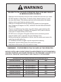
WARNING
FAILURE TO FOLLOW SAFE OPERATING PRACTICES MAY RESULT
IN SERIOUS INJURY OR DEATH.
• Read this manual completely as well as other manuals that came with your mower.
• DO NOT operate on steep slopes. To check a slope, attempt to back up it (with
the cutter deck down). If the machine can back up the slope without the wheels
slipping, reduce speed and use extreme caution.
• Under no circumstances should the machine be operated on slopes greater
than 15 degrees (20 degrees for SVR). ALWAYS FOLLOW OSHA APPROVED
OPERATION.
• Stay two cut widths away from slopes, drop os, ditches, water,retaining walls,
avoid any slope exceeding 15 degrees (20 degrees for SVR), and do not mow
under trees on slopes with the roll bar down.
• DO NOT mow on wet grass. Wet grass reduces traction and steering control.
• Keep all shields in place, especially the grass discharge chute.
• Before performing any maintenance or service, stop the machine and remove the
spark plug wire and ignition key.
• If a mechanism becomes clogged, stop the engine before cleaning.
• Keep hands, feet and clothing away from power-driven parts.
• Keep others o the mower (only one person at a time)
REMEMBER - YOUR MOWER IS ONLY AS SAFE AS THE OPERATOR!
HAZARD CONTROL AND ACCIDENT PREVENTION ARE DEPENDENT UPON THE AWARENESS,
CONCERN, PRUDENCE, AND PROPER TRAINING OF THE PERSONNEL INVOLVED IN THE
OPERATION, TRANSPORT, MAINTENANCE, AND STORAGE OF THE EQUIPMENT.
This manual covers the operating instructions and illustrated parts list for:
STCII-48V E-OCDC-RF with a part number of 924Z
STCII-52V E-OCDC-RF with a part number of 925A
STCII-61V E-OCDC-RF with a part number of 925B
STTII-52V E-OCDC-RF with a part number of 925C
SCZII/STTII-61V E-OCDC-RF with a part number of 925D
SCZII/STTII-72V E-OCDC-RF with a part number of 925J
SVRII-48V E-OCDC-RF with a part number of 924U
SVRII-52V E-OCDC-RF with a part number of 924V
ISVRII-61V E-OCDC-RF with a part number of 924W

I
R
Table of Contents
Table of Contents
SECTION 1 - GENERAL INFORMATION ................................................................................... 1
1.1 INTRODUCTION .........................................................................................................................................1
1.2 DIRECTION REFERENCE .........................................................................................................................1
1.3 SERVICING THIS ACCESSORY ...............................................................................................................1
1.4 SYMBOLS .................................................................................................................................................... 2
SECTION 2 - SAFETY INFORMATION ......................................................................................3
2.1 INTRODUCTION .........................................................................................................................................3
2.2 SIGNAL WORDS .........................................................................................................................................3
2.3 OPERATION CONSIDERATIONS .............................................................................................................3
2.4 E-OCDC OPERATION ................................................................................................................................4
2.5 BATTERY REPLACEMENT ........................................................................................................................5
2.6 RF MODULE PAIRING ...............................................................................................................................5
SECTION 3 - INSTALLATION INSTRUCTIONS ........................................................................6
3.1 STCII/SVRII-48V/52V & STTII-52V BLOCK OFF PLATE INSTALLATION INSTRUCTIONS ................ 6
3.2 SVRII/STCII/SCZII/STTII-61V BLOCK OFF PLATE INSTALLATION INSTRUCTIONS ........................ 9
3.3 STTII/SCZII-72V BLOCK OFF PLATE INSTALLATION INSTRUCTIONS ............................................ 11
3.4 STCII RF CONTROL MODULE AND DRIVE HANDLE INSTALLATION INSTRUCTIONS ................. 14
3.5 STTII RF CONTROL MODULE AND DRIVE HANDLE INSTALLATION INSTRUCTIONS .................16
3.6 SVRII RF CONTROL MODULE AND DRIVE HANDLE INSTALLATION INSTRUCTIONS .................18
3.7 SCZII RF CONTROL MODULE AND DRIVE HANDLE INSTALLATION INSTRUCTIONS ................. 19
SECTION 4 - ILLUSTRATED PARTS LIST ..............................................................................22
4.1 SCAG APPROVED ATTACHMENTS AND ACCESSORIES. ................................................................. 22
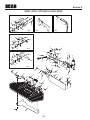
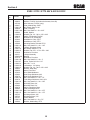
SVRII / STCII / STTII 48V & 52V E-OCDC ....................................................................................................24
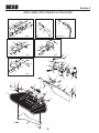
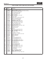
STCII / SCZII / STTII / SVR 61V & 72V E-OCDC .......................................................................................... 26
LIMITED WARRANTY- COMMERCIAL ACCESSORY ...............................................INSIDE BACK COVER

1
R
Section 1
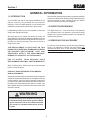
1.1 INTRODUCTION
Your E-OCDC was built to the highest standards in the
industry. However, the prolonged life and maximum
efficiency of your E-OCDC depends on you following the
installation and operation instructions in this manual.
If additional information or service is needed, contact your
Scag Power Equipment Dealer.
We encourage you to contact your dealer for repairs. All
Scag dealers are informed of the latest methods to service
this equipment and provide prompt and efficient service in
the field or at their service shop. They carry a full line of
Scag service parts.
THE REPLACEMENT OF ANY PART ON THIS
PRODUCT BY OTHER THAN THE MANUFACTURER'S
AUTHORIZED REPLACEMENT PART MAY
ADVERSELY AFFECT THE PERFORMANCE,
DURABILITY OR SAFETY OF THIS PRODUCT.
USE OF OTHER THAN ORIGINAL SCAG
REPLACEMENT PARTS WILL VOID THE WARRANTY.
When ordering parts, always give the model and part
number of this accessory.
USE ONLY SCAG APPROVED ATTACHMENTS
AND ACCESSORIES.
Attachments and accessories manufactured by companies
other than Scag Power Equipment are not approved for use
on this machine. See your mowers operator's manual for
a complete list of approved attachments and accessories.
Be aware that using attachments with the mower may
affect stability. Be sure to follow the directions found in the
operator's manual.
WARNING
For pictorial clarity, some illustrations and gures
in this manual may show shields, guards or plates
open or removed. Under no circumstances should
your mower be operated without these devices
in place.
GENERAL INFORMATION
All information is based upon product information available
at the time of approval for printing. Scag Power Equipment
reserves the right to make changes at any time without
notice and without incurring any obligation.
1.2 DIRECTION REFERENCE
The “Right” and “Left”, “Front” and “Rear” of the machine
are referenced from the operator’s right and left when
seated in the normal operating position and facing the
forward travel direction.
1.3 SERVICING THIS ACCESSORY
For service of this accessory during the limited warranty
period, it is important to contact your Scag dealer. Any
unauthorized work done to this accessory during the
warranty period may void your warranty.

2
R
Section 1
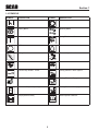
1.4 SYMBOLS
SYMBOL DESCRIPTION SYMBOL DESCRIPTION
Choke
Transmission
Parking Brake
48071S
Spinning Blade
On/Start
Spring Tension on Idler
O/Stop
Oil
Falling Hazard
Thrown Object Hazard
Fast
Slow
Continuously Variable - Linear
Cutting Element - Basic Symbol
481039S
Pinch Point
Cutting Element - Engage
Hour meter/Elapsed Operating Hours
Cutting Element - Disengage
Keep Bystanders Away
Read Operator's Manual

3
R
Section 2
2.1 INTRODUCTION
Your mower is only as safe as the operator. Carelessness
or operator error may result in serious bodily injury or death.
Hazard control and accident prevention are dependent
upon the awareness, concern, prudence, and proper
training of the personnel involved in the operation, transport,
maintenance and storage of the equipment. Make sure
every operator is properly trained and thoroughly familiar
with all of the controls before operating the mower. The
owner/user can prevent and is responsible for accidents or
injuries occurring to themselves, other people or property.
READ THIS OPERATOR’S MANUAL AND WATCH
THE TIPS FOR SAFE OPERATION OF YOUR
SCAG ZERO-TURN MOWER VIDEO BEFORE
ATTEMPTING TO START YOUR MOWER. MAKE
SURE THAT EVERYONE KNOWS WHERE THE
MANUAL IS LOCATED AND KEEP A RECORD OF
EACH EMPLOYEE THAT HAS READ THE MANUAL.
A replacement manual is available from your authorized
Scag Service Dealer or by contacting Scag Power
Equipment, Service Department at P.O. Box 152, Mayville,
WI 53050 or contact us via the Internet at www.scag.com.
The manual for this accessory can be downloaded by
using the model and part number or use the contact form
to make your request. Please indicate the complete model
and part number of your Scag product when requesting
replacement manuals.
2.2 SIGNAL WORDS
This symbol means “Attention! Become Alert! Your
Safety is Involved!" The symbol is used with the following
signal words to attract your attention to safety messages
found on the decals on the machine and throughout this
manual. The message that follows the symbol contains
important information about safety. To avoid injury and
possible death, carefully read the message! Be sure to
fully understand the causes of possible injury or death.
SIGNAL WORD:
It is a distinctive word found on the safety decals on the
machine and throughout this manual that alerts the viewer
to the existence and relative degree of the hazard.
DANGER
The signal word “DANGER” denotes that an extremely
hazardous situation exists on or near the machine that
could result in high probability of death or irreparable injury
if proper precautions are not taken.
WARNING
The signal word “WARNING” denotes that a hazard exists
on or near the machine that can result in injury or death if
proper precautions are not taken.
CAUTION
The signal word “CAUTION” is a reminder of safety
practices on or near the machine that could result in
personal injury if proper precautions are not taken.
Your safety and the safety of others depends significantly
upon your knowledge and understanding of all correct
operating practices and procedures of this machine.
2.3 OPERATION CONSIDERATIONS
1. Know the function of the E-OCDC control before
operating the machine.
WARNING
DO NOT operate without discharge chute, mulch
kit, mulch plate, OCDC, E-OCDC or entire grass
catcher installed.
SAFETY INFORMATION

4
R
Section 2
2. When using any attachment, never direct the
discharge of material toward bystanders or allow
anyone near the machine while in operation.
3. If the mower discharge ever plugs, shut off the
engine, remove the ignition key, and wait for all
movement to stop before removing the obstruction.
WARNING
DO NOT use your hand to dislodge the clogged
discharge chute. Use a stick or other device to
remove clogged material after the engine has
stopped running and the blades have stopped
turning.
4. Be alert for holes, rocks, roots and other hidden
hazards in the terrain. Keep away from any drop-
offs. Beware of overhead obstructions (low limbs,
etc.), underground obstacles (sprinklers, pipes, tree
roots, etc.). Cautiously enter a new area. Be alert for
hidden hazards.
5. Disengage power to cutter deck before backing up.
Do not mow in reverse unless absolutely necessary
and then only after observation of the entire area
behind the mower. If you must mow in reverse,
maintain a constant lookout to the rear of the
machine and mow slowly.
6. Disengage power to cutter deck before crossing
roads, walks or gravel drives.
7. Mow only in daylight or good artificial light.
8. NEVER raise the deck with the blades engaged.
9. The machine and attachments should be stopped
and inspected for damage after striking a foreign
object, and damage should be repaired before
restarting and operating the machine.
10. Keep hands and feet away from cutter blades and
moving parts. Contact can injure.
11. Use care when approaching blind corners, shrubs,
trees, or other objects that may obscure vision.
12. NEVER leave the machine running unattended.
2.4 E-OCDC OPERATION
The E-OCDC (Electric Operator Controlled Discharge
Chute) can be raised or lowered to side discharge or block
the discharge of grass clippings. Follow the steps below
for proper operation of the E-OCDC.
-NOTE-
The E-OCDC is not intended to be a complete
or full-time mulch system. This accessory allows
the operator to temporarily close the cutter
deck's discharge opening to keep clippings out
of landscaping and off pavement when needed.
CLOSED POSITION
In the closed position, the clippings will be temporarily
blocked.
1. Press the control switch once to lock the E-OCDC
into the closed position. The discharge chute will
raise to allow for close trimming.
OPEN POSITION
In the open position, the clippings will side discharge.
1. Press the control switch again to lower the side
discharge chute. The discharge chute will lower
to it's original position for safe side-discharge
operation.

5
R
Section 2
2.5 BATTERY REPLACEMENT
1. Locate the RF control switch. The switch will either
be located in the RH steering control lever for ride-
on models or just in front of the steering control
levers on stand-on models.
2. Remove the switch by pulling the switch straight out
of the mounting area. It may be necessary to use a
flat head screwdriver to assist with the removal.
3. Locate the battery cover on the RF switch and
remove the two phillip screws retaining the cover to
the switch.
4. Remove the battery cover and battery.
5. Install the new 1632 battery with the positive side
facing up in the sleeve in the RF switch.
6. Install the battery cover and screws.
7. Install the switch back into the RH drive handle.
8. Be sure to dispose of the old battery properly.
2.6 RF MODULE PAIRING
-NOTE-
The pairing procedure will need to be completed
whenever the RF control switch or control module
is replaced.
1. Press the green pair switch on the RF control
module located on the side of the machine by the
discharge opening.
2. Press the RF control switch within 3 seconds of
pressing the green pair switch. The green pair
switch light on the control box will flash once,
indicating it has been paired successfully. If the
handle bar switch is not pressed within 3 seconds,
the pairing process will be canceled and the light
will not flash. Repeat steps 1 and 2 if this occurs to
complete the pairing process.

6
R
Section 3
3.1 STCII/SVRII-48V/52V & STTII-52V
BLOCK OFF PLATE INSTALLATION
INSTRUCTIONS
Prepare the machine so there is easy and safe access to
the work area. Park the machine on a flat, level surface
and apply the parking brake. Remove the ignition key
and disconnect the positive and negative cables from the
battery. Maintain all safety related work procedures. Always
wear hand and eye protection.
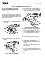
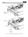
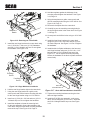
1. Remove the discharge chute from the machine. See
Figure 3-1.
2. Retain the discharge chute and mounting hardware
for future use.
Remove &
Retain
Figure 3-1. Removing the Discharge Chute
3. Remove the turbo baffle from the cutter deck. See
Figure 3-2.
4. Retain the turbo baffle and mounting hardware for
future use.
Remove &
Retain
Figure 3-2. Removing the Turbo Bae
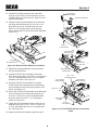
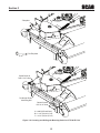
INSTALLATION INSTRUCTIONS
5. Install the rear hinge bracket to the cutter deck using
one (1) 5/16-18 x 1" bolt, one (1) 5/16" flatwasher
and one (1) 5/16-18 elastic stop nut. Do not tighten
the hardware. See Figure 3-3.
Rear Hinge
Bracket
Front Hinge
Bracket
Figure 3-3. Hinge Weldment Installation
6. Hold the rear hinge bracket tight to the cutter deck.
7. Using the rear hinge bracket as a guide, mark,
center punch and drill the bottom mounting bolt hole
for the rear hinge bracket using an 11/32" drill bit.
8. Install one (1) 5/16-18 x 3/4" bolt and one (1) 5/16-
18 elastic stop nut. Do not tighten the hardware.
9. Install the template to locate the mounting hole
for the pivot assembly. Secure the template to the
cutter deck using the turbo baffle mounting hardware
removed in step 5. See Figure 3-4, Page 7.
10. Hold the template against the discharge chute
mounting rail and tighten the hardware. See Figure
3-4, Page 7.
11. Using the template as a guide, center punch and
drill one mounting hole using an 11/32" drill bit. See
Figure 3-4, Page 7.
12. Remove the template from the cutter deck.
13. Carefully lay out the remaining mounting holes for
the front hinge bracket in the cutter deck. See Figure
3-4, Page 7.
14. Center punch and drill the holes using an 11/32" drill
bit.

7
R
Section 3
B
C
Center Punch &
Drill 11/32” Hole
Center Punch &
Drill 11/32” Hole
Discharge Chute
Mounting Rail
A
A = 0.40” (48V)
B = 3” (48V)
C = 3-3/4” (48V)
A = 0.40” (52V)
B = 3-3/4” (52V)
C = 4-1/2” (52V)
*Template
*48V Template
Template
*52V Template
Figure 3-4. Locating and Drilling the Mounting Holes for STC/STCII/SCZ-48V

8
R
Section 3
15. Install the front hinge bracket to the cutter deck
using two (2) 5/16-18 x 3/4" bolts and two (2) 5/16-
18 elastic stop nuts. See Figure 3-3, Page 6. Do not
tighten the hardware.
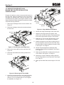
16. Install the block off plate weldment to the front and
rear hinge brackets using two (2) 5/16-18 x 3-1/2"
bolts and two (2) 5/16-18 elastic stop nuts. See
Figure 3-5. Do not tighten the bolts completely.
Secure the hardware so the block off plate weldment
moves freely.
Block O
Plate
Weldment
Figure 3-5. Block O Plate Weldment Installation
17. Tighten the mounting hardware securing the front
and rear hinge brackets.
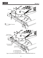
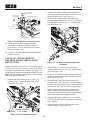
18. Install the E-OCDC pivot assembly to the cutter
deck. Secure using one (1) 5/16-18 x 1" bolt and one
(1) 5/16-18 flanged elastic stop nut. Do not tighten
hardware at this time. See Figure 3-6.
19. Using the E-OCDC pivot assembly as a guide,
locate and drill the required holes in the discharge
chute mounting rail and cutter deck using an 11/32"
drill bit. See Figure 3-6.
20. Secure the E-OCDC pivot assembly to the discharge
chute mounting rail and cutter deck using two (2)
5/16-18 x 1" bolts, two (2) 5/16-18 flanged elastic
stop nuts and one (1) 3/8" x 1-1/4" self tapping
screw. See Figure 3-6.
21. Fasten the lower adjustable linkage to the block off
weldment using one (1) 5/16" -18 x 1-1/4" bolt, one
(1) 5/16" flat washer and one (1) 5/16" elastic stop
nut. See Figure 3-6.
22. Tighten the hardware installed in steps 20 and 22.
OCDC Pivot Assembly
Discharge Chute
Mounting Rail
Center Punch &
Drill 11/32” Hole
Center Punch &
Drill 11/32” Hole
5/16” x 1”
Hex Head Bolt
5/16” x 1”
Hex Head Bolt
5/16” Flanged
Elastic Stop Nut
5/16” Flanged
Elastic Stop Nut
5/16” Flanged
Elastic Stop Nut
3/8” x 1-1/4”
Self Tapping Screw
5/16-18” x 1-1/4”
Bolt
5/16” Elastic
Stop Nut
Figure 3-6. STC/STCII/SCZ-48V/52V Pivot Bracket
Install

9
R
Section 3
3.2 SVRII/STCII/SCZII/STTII-61V
BLOCK OFF PLATE INSTALLATION
INSTRUCTIONS
Prepare the machine so there is easy and safe access to
the work area. Park the machine on a flat, level surface
and apply the parking brake. Remove the ignition key
and disconnect the positive and negative cables from the
battery. Maintain all safety related work procedures. Always
wear hand and eye protection.
1. Remove the discharge chute from the machine. See
Figure 3-7.
2. Retain the discharge chute and mounting hardware
for future use.
Remove &
Retain
Figure 3-7. Removing the Discharge Chute
3. Remove the turbo baffle from the cutter deck. See
Figure 3-8.
4. Retain the turbo baffle and mounting hardware for
future use.
Remove &
Retain
Figure 3-8. Removing the Turbo Bae
5. Install the rear hinge bracket to the cutter deck using
one (1) 5/16-18 x 1" bolt, one (1) 5/16" flatwasher
and one (1) 5/16-18 elastic stop nut. Do not tighten
the hardware. See Figure 3-9.
Rear Hinge
Bracket
Front Hinge
Bracket
Figure 3-9. Hinge Weldment Installation
6. Hold the rear hinge bracket tight to the cutter deck.
7. Using the rear hinge bracket as a guide, mark,
center punch and drill the bottom mounting bolt hole
for the rear hinge bracket using an 11/32" drill bit.
8. Install one (1) 5/16-18 x 3/4" bolt and one (1) 5/16-
18 elastic stop nut. Do not tighten the hardware.
9. Install the template to locate the mounting holes for
the lever assembly. Secure to the cutter deck using
the turbo baffle mounting hardware removed in step
5. See Figure 3-10, Page 10.
10. Hold the template against the discharge chute
mounting rail and tighten the hardware. See Figure
3-10, Page 10.
11. Center punch and drill the mounting holes using an
11/32" drill bit. See Figure 3-10, Page 10.
12. Carefully lay out the remaining mounting holes for
the front hinge bracket in the cutter deck. See Figure
3-10, Page 10.
13. Center punch and drill the holes using an 11/32" drill
bit.

10
R
Section 3
B
C
*Template
Template
Center Punch &
Drill 11/32” Hole
Center Punch &
Drill 11/32” Hole
Discharge Chute
Mounting Rail
A
A = 0.40” (All Deck Sizes)
B = 3-3/4” (52V, 61V, 72V)
C = 4-1/2” (52V, 61V, 72V)
*61V Template
Figure 3-10. Locating and Drilling the Mounting Holes for STCII/SVRII/STTII/SCZII -61V

11
R
Section 3
14. Install the front hinge bracket to the cutter deck
using two (2) 5/16-18 x 3/4" bolts and two (2) 5/16-
18 elastic stop nuts. See Figure 3-9, page 9. Do not
tighten the hardware.
15. Install the block off plate weldment to the front and
rear hinge brackets using two (2) 5/16-18 x 3-1/2"
bolts and two (2) 5/16-18 elastic stop nuts. See
Figure 3-11. Do not tighten the bolts completely.
Secure the hardware so the block off plate weldment
moves freely.
Block O
Plate
Weldment
Figure 3-11. Block O Plate Weldment Installation
16. Tighten the mounting hardware securing the front
and rear hinge brackets.
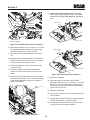
17. Install the E-OCDC pivot assembly to the cutter
deck. Secure using two (2) 5/16-18 x 1" bolts and
two (2) 5/16-18 flanged elastic stop nuts. Do not
tighten the hardware at this time. See Figure 3-12.
18. Secure the lower adjustable linkage to the block off
plate weldment using one (1) 5/16" -18 x 1-1/2", one
(1) spacer, and one (1) 5/16" elastic stop nut. See
Figure 3-12.
19. Tighten the hardware installed in step 18 leaving a
1/16" gap between the E-OCDC pivot assembly and
the discharge chute mounting rail on the cutter deck.
See Figure 3 -13.
OCDC Pivot Assembly
61V Cutter Deck
5/16” - 18 x 1.50”
Hex Head Bolt
5/16” - 18 Flanged
Elastic Stop Nuts
5/16” - 18 x 1”
Hex Head Bolt
5/16” - 18 Elastic
Stop Nut
Spacer
Figure 3-12. STCII/SVRII/STTII/SCZII /61V Pivot Install
61V Cutter Deck
1/16” Gap
Figure 3-13. Gap Requirement
3.3 STTII/SCZII-72V BLOCK OFF PLATE
INSTALLATION INSTRUCTIONS
Prepare the machine so there is easy and safe access to
the work area. Park the machine on a flat, level surface
and apply the parking brake. Remove the ignition key
and disconnect the positive and negative cables from the
battery. Maintain all safety related work procedures. Always
wear hand and eye protection.
1. Remove the discharge chute from the machine. See
Figure 3-14.
2. Retain the discharge chute and mounting hardware
for future use.
Remove &
Retain
Figure 3-14. Removing the Discharge Chute
3. Remove the turbo baffle from the cutter deck. See
Figure 3-15.
4. Retain the turbo baffle and mounting hardware for
future use.

12
R
Section 3
Remove &
Retain
Figure 3-15. Removing the Turbo Bae
5. Install the rear hinge bracket to the cutter deck using
one (1) 5/16-18 x 1" bolt, one (1) 5/16" flatwasher
and one (1) 5/16-18 elastic stop nut. Do not tighten
the hardware. See Figure 3-16.
Rear Hinge
Bracket
Front Hinge
Bracket
Figure 3-16. Hinge Weldment Installation
6. Hold the rear hinge bracket tight to the cutter deck.
7. Using the rear hinge bracket as a guide, mark,
center punch and drill the bottom mounting bolt hole
for the rear hinge bracket using an 11/32" drill bit.
8. Install one (1) 5/16-18 x 3/4" bolt and one (1) 5/16-
18 elastic stop nut. Do not tighten the hardware.
9. Install the template to locate the mounting hole
for the pivot assembly. Secure the template to the
cutter deck using the turbo baffle mounting hardware
removed in step 5. See Figure 3-18, Page 13.
10. Hold the template against the discharge chute
mounting rail and tighten the hardware. See Figure
3-18, Page 13.
11. Using the template as a guide, center punch and
drill two mounting holes using an 11/32" drill bit. See
Figure 3-18, Page 13.
12. Remove the template from the cutter deck.
13. Carefully lay out the remaining mounting holes for
the front hinge bracket in the cutter deck. See Figure
3-18 Page 13.
14. Center punch and drill the holes using an 11/32" drill
bit
15. Install the front hinge bracket to the cutter deck
using two (2) 5/16-18 x 3/4" bolts and two (2) 5/16-
18 elastic stop nuts. See Figure 3-18. Do not tighten
the hardware.
16. Install the block off plate weldment to the front and
rear hinge brackets usting two (2) 5/16 -18 x 3 1/2"
bolts and two (2) 5/16-18 elastic stop nuts. See
Figure 3-17. Do not tighten the bolts completely.
Secure the hardware so the block off plate weldment
moves freely.
Block O
Plate Weldment
Figure 3-17. Block O Plate Weldment Installation
17. Tighten the mounting hardware securing the front
and rear hinge brackets.
18. Install the E-OCDC pivot assembly to the cutter
deck. Secure using two (2) 5/16-18 x 1" bolts and
two 5/16-18 flanged elastic stop nuts. See Figure
3-19.

13
R
Section 3
B
C
*Template
Template
Center Punch &
Drill 11/32” Hole
Center Punch &
Drill 11/32” Hole
Discharge Chute
Mounting Rail
A
A = 0.40” (All Deck Sizes)
B = 3-3/4” (52V, 61V, 72V)
C = 4-1/2” (52V, 61V, 72V)
*72V Template
Figure 3-18. Locating and Drilling the Mounting Holes for STTII/SCZII -72V

14
R
Section 3
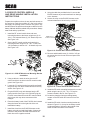
2. Install the RF control module mounting bracket to
the cutting height bracket using the 5/16-18 x 1 1/4"
bolts removed in step 1. See Figure 3 -21.
3. Secure the RF control module and guard to the
mounting bracket using two (2) 1/4-20 x 1" bolts, two
1/4" flat washers, and two (2) 1/4" - 20 elastic stop
nuts. See Figure 3-21.
Figure 3-21. RF Module and Mounting Bracket
Installation
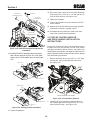
4. Using a cable tie, retain the wires from the RF
control module to the hole in the RF control module
guard. See Figure 3-22.
5. Locate the "A" terminal on the key switch and install
the green wire from the E-OCDC harness to the key
switch. See Figure 3-22.
6. Plug the EOCDC main wire harness into the RF
control module. See Figure 3-22. DO NOT plug the
EOCDC motor harness into the RF control module at
this time, this may cause movement of the linkages.
7. Install the wires from the E-OCDC harness to the
battery using the red and black leads. Be sure to
connect the red wire to the positive terminal first and
then the black wire to the negative terminal.
8. Using the cable ties provided in the kit, secure the
E-OCDC harness to prevent interference or damage
to the harness.
9. Secure the relay on the E-OCDC harness to the
main wire harness using a cable tie.
OCDC Pivot Assembly
72V Cutter Deck
5/16” - 18 x 1.50”
Hex Head Bolt
5/16” - 18 x 1”
Hex Head Bolt
5/16” - 18 Flanged
Elastic Stop Nuts
5/16” - 18 Elastic
Stop Nut
Spacer
.
Figure 3-19. 72V OCDC Pivot Assembly Install
19. Fasten the lower control linkage of the pivot
assembly to the block off weldment using one
(1) 5/16-18 x 1-1/2" bolt, spacer and 5/16" elastic
locknut. See Figure 3-21.
20. Leaving a 1/16" gap, tighten the hardware installed
in Step 18 and 19.
3.4 STCII RF CONTROL MODULE
AND DRIVE HANDLE INSTALLATION
INSTRUCTIONS
Prepare the machine so there is easy and safe access to
the work area. Park the machine on a flat, level surface
and apply the parking brake. Remove the ignition key
and disconnect the positive and negative cables from the
battery. Maintain all safety related work procedures. Always
wear hand and eye protection.
1. Remove and retain the two (2) 5/16 - 18 x 1 1/4"
bolts securing the cutting height bracket to the
frame. See Figure 3-20.
Remove and Retain
5/16” -18 Bolts
Figure 3-20. STCII Hardware Removal

15
R
Section 3
Cable Tie
OCDC Motor to
RF Control Module
RF Control Module
OCDC Main
Wire Harness
To the Battery &
Key Switch
Figure 3-22. E-OCDC Wire Harness Installation
10. Remove and retain the two (2) 3/8-16 x 1 1/4" bolts,
lock washers and flat washers securing the right
hand drive handle to the control lever bar.
11. Remove the RH handle and retain for any future
use.
12. Install the right hand drive handle included with the
EOCDC kit to the control lever bar by re-using the
hardware that was removed in step 11.
13. Tighten the hardware securing the handle to the
control lever bar.
14. Locate the plastic pull strip preventing battery
contact on the RF switch and remove it from the
switch.
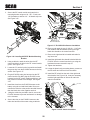
15. Install the RF switch into the end of the right hand
drive handle. See Figure 3-23. It may be necessary
to add a light application of silicone to retain the
switch in the handle.
RF Switch
Figure 3-23. RF Switch Installation
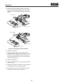
16. Install the EOCDC discharge chute to the cutter
deck. Secure using two (2) 5/16-18 x 1 3/4" bolts
and two (2) 2 5/16-18 elastic stop nuts. See Figure
3-24.
61V/72V Cutter Dec
k
A
B
Upper Control
Link
B
A
A
A
B
B
OCDC Discharge
Chute
Upper Control
Link
48/52” Cutter Deck
OCDC Discharge
Chute
Figure 3-24. Discharge Chute Installation
17. Tighten the hardware.
18. Secure the upper control link to the E-OCDC
discharge chute using one (1) 5/16-18 x 1 11/2" bolt
and one (1) 5/16-18 elastic stop nut. A spacer will
be required to install the 61 and 72 inch discharge
chutes. See Figure 3-24.
19. Tighten the hardware.
20. Connect the E-OCDC motor wire harness to the RF
control module.
21. Operate the E-OCDC checking for proper operation
as outlined in Section 2.4, pages 4 and 5.
22. An adjustment may need to be made to the lower
control link to ensure smooth operation.

16
R
Section 3
3.5 STTII RF CONTROL MODULE
AND DRIVE HANDLE INSTALLATION
INSTRUCTIONS
Prepare the machine so there is easy and safe access to
the work area. Park the machine on a flat, level surface
and apply the parking brake. Remove the ignition key
and disconnect the positive and negative cables from the
battery. Maintain all safety related work procedures. Always
wear hand and eye protection.
1. Remove and retain the two (2) 5/16-18 x 1 1/4" bolts
securing the cutting height bracket to the frame.
See Figure 3-25.
Remove and Retain
5/16” -18 Bolts
Figure 3-25. STTII Hardware Removal
2. Install the RF control module mounting bracket to
the cutting height bracket using the 5/16 - 18 x 1 1/4"
bolts removed in step 1. See Figure 3-25.
3. Secure the RF control module and guard to the
mounting bracket using two (2) 1/4-20 x 1" bolts, two
(2) 1/4" flat washers, and two (2) 1/4-20 elastic stop
nuts. See Figure 3-26.
Figure 3-26. RF Module and Mounting Bracket
Installation
4. Using a cable tie, retain the wires from the RF
control module to the hole in the RF control module
guard. See Figure 3-27.
5. Locate the "A" terminal on the key switch and install
the green wire from the E-OCDC harness to the key
switch. See Figure 3-27.
6. Plug the EOCDC main wire harness into the RF
control module. See Figure 3 -27. DO NOT plug the
EOCDC motor harness into the RF control module at
this time, this may cause movement of the linkages.
7. Route the battery leads of the E-OCDC wire harness
along the frame rail on the right side of the unit
towards the battery.
8. Install the wires from the EOCDC harness to the
battery using the red and black leads. Connect the
red wire to the positive terminal first and then the
black wire to the negative terminal.
9. Using the cable ties provided in the kit, secure the
OCDC harness to prevent interference or damage to
the harness.
10. Secure the relay on the E-OCDC harness to the
main wire harness of the unit using a cable tie.

17
R
Section 3
To Battery & Key
Switch
Cable Tie
RF Control Module
OCDC Motor to
RF Control Module
Figure 3-27. E-OCDC Wire Harness Installation
11. Remove and retain the two (2) 3/8-16 x 1 1/4" bolts,
lock washers and flat washers securing the right
hand drive handle to the control lever bar.
12. Remove the right hand drive handle and retain for
any future use.
13. Install the right hand drive handle included with the
EOCDC kit to the control lever bar by re-using the
hardware that was removed in step 11.
14. Tighten the hardware securing the right hand drive
handle to the control lever bar.
15. Locate the plastic strip preventing battery contact on
the RF switch and remove it from the switch.
16. Install the RF switch into the end of the right hand
drive handle. See Figure 3-28. It may be necessary
to add a light application of silicone to retain the
switch in the handle.
RF Switch
Figure 3-28. RF Switch Installation
17. Install the EOCDC discharge chute to the cutter
deck. Secure using two (2) 5/16-18 x 1 3/4" bolts
and two (2) 5/16-18 elastic stop nuts. See Figure
3-29.
61V/72V Cutter Dec
k
A
B
Upper Control
Link
B
A
A
A
B
B
OCDC Discharge
Chute
Upper Control
Link
48/52” Cutter Deck
OCDC Discharge
Chute
Figure 3-29. Discharge Chute Installation
18. Tighten the hardware.
19. Secure the upper control link to the EOCDC
discharge chute using one (1) 5/16-18 x 1 1/4" bolt
and one (1) 5/16-18 elastic stop nut. See Figure
3-29.
20. Tighten the hardware.
21. Connect the E-OCDC motor wire harness to the RF
control module.
22. Operate the E-OCDC checking for proper operation
as outlined in Section 2.4, pages 4 and 5.
23. An adjustment may need to be made to the lower
control link to ensure smooth operation.
Page is loading ...
Page is loading ...
Page is loading ...
Page is loading ...
Page is loading ...
Page is loading ...
Page is loading ...
Page is loading ...
Page is loading ...
Page is loading ...
Page is loading ...
-
 1
1
-
 2
2
-
 3
3
-
 4
4
-
 5
5
-
 6
6
-
 7
7
-
 8
8
-
 9
9
-
 10
10
-
 11
11
-
 12
12
-
 13
13
-
 14
14
-
 15
15
-
 16
16
-
 17
17
-
 18
18
-
 19
19
-
 20
20
-
 21
21
-
 22
22
-
 23
23
-
 24
24
-
 25
25
-
 26
26
-
 27
27
-
 28
28
-
 29
29
-
 30
30
-
 31
31


Scag Power Equipment Electric type - 924Z, 925A, 925B, 925C, 925D, 925J, 924U, 924V, 924W User manual
- Type
- User manual
Ask a question and I''ll find the answer in the document
Finding information in a document is now easier with AI
Related papers
-
Scag Power Equipment Tiger Cat II User manual
-
 Scag Power Equipment GC-CS Clam Shell Grass Catcher User manual
-
 Scag Power Equipment STT-OCDC-52V User manual
-
-
 Scag Power Equipment Turf Tiger II User manual
-
Scag Power Equipment STT-OCDC-52V User manual
-
 Scag Power Equipment Cheetah II User manual
-
 Scag Power Equipment SVR52V-23FX User manual
-
Scag Power Equipment Tiger Cat User manual
-
 Scag Power Equipment STC61V-25CV User manual


Other documents
-
Western Baffle Replacement Kit Installation guide
-
Toro LED Light Kit, TimeCutter HD Riding Mower Installation guide
-
Ransomes 4420786 Owner's manual
-
Ransomes ZT1000 Series Owner's manual
-
-
 Dixie Chopper Xcaliber CNG Owner's manual
-
-
