Installation instructions
Thermal screen
for glass ceramic hobs
J40270-R14
6.4.18
4
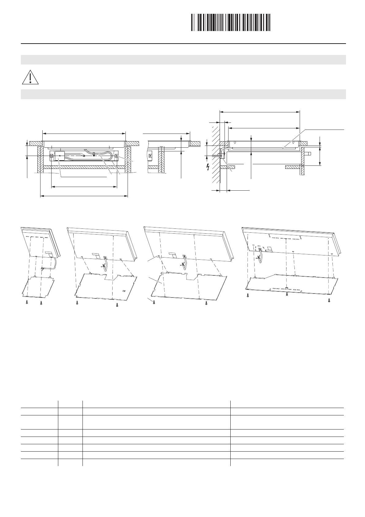
* Cut-out in side panels
1. Install and wire the branch connector.
2. Drill 2 holes A ø 6 mm in the rear panel and insert plugs B.
3. Fit cable protection plate C (model 005 without cable protection plate) using the wood screws supplied.
4. Introduce the thermal screen D into the rear slot E and screw mount to the hob tray using screws F.
5. Place the hob in position.
6. Place the mains cable G in the cable protection plate C.
Thermal screen sets
Electrical connection
The thermal screen set must be used when a drawer is installed directly in a base unit and where the tray can be contacted
from below without the aid of tools.
Installation
Art. no. Pos. Modell no. hob Notice
H6.2542 1 005, 31023, 31110 BG 30 without cable protection plate H6.2032
H6.2622 2
032, 039, 040, 97A, 31024, 31025, 31027, 31028, 31033,
31103–31106
BG 60 + 70
H6.2782 3 31004 –
H6.3266 4 31032 BG 80 Panorama
H6.2617 5 977, 31026, 31005, 31107 BG 80
H6.2616 6 976, 31108 BG 90 Panorama
H6.3280 7 31042, 31109 BG 90
450
275, 550, 600, 900
min. 70
70
min. 40
A/B
GC
28
C
127 3
min. 63.5
Cut-out Cut-out
Cut-out*
(flush mounted)
Cut-out*
(with frame)
Thermal screen
Drawer
min. 63.5
Cut-out
Branch connector
