Page is loading ...

Theater 7 Power Amplifier
SETUP GUIDE
Getting Started
THE LEADER IN AUDIO ENGINEERING
Krell’s history is rich with breakthrough Class A amplifiers that have helped build
the Krell legacy of offering the best sounding amplifiers available. Audiophiles have
always considered Class A technology to be the best sounding operating state for
amplifiers. However, despite Class A’s unrivaled sound quality, it has fallen out
of fashion because of recent demands to reduce power consumption and heat in
home electronics products. Krell engineering took this challenge and redefined the
meaning of high performance power amplifier. Our goal – unmatched performance,
elegant design, and a compelling array of features. The breakthrough, iBias, a
patent pending circuit delivering Class A operation without the excessive heat
and wasted energy of conventional designs, housed in a striking new form factor,
with network connectivity for advanced access and monitoring. The sound is open
and unconstrained, in a manner that rivals live performance and the true sound of
voices and instruments. Music and dialogue are reproduced with a richness, detail,
and startling dynamics that fill a room.The Theater 7 amplifier is easy to operate and
integrate into your system.
Do not place the amplifier where it could be exposed to dripping or splashing.
Do not remove or bypass the ground pin on the end of the AC cord. This may cause radio
frequency interference (RFI) to be introduced into your playback system.
The ventilation slots on the top and bottom of the amplifier as well as the fan openings on the
bottom must be unobstructed at all times during operation. Do not place flammable material on top
of or beneath the component.
Turn off all systems’ power before connecting the amplifier to any component.
Make sure all cable terminations are of the highest quality, free from frayed ends, short circuits, or
cold solder joints.
THERE ARE NO USER-SERVICEABLE PARTS INSIDE ANY KRELL PRODUCT.
1. Open the shipping box and remove the top layer of foam. You will see these items:
2. Carefully remove all items from the shipping box.
3. Place the amplifier in a safe location and remove the protective plastic wrapping.
WARNINGS
Krell Theater 7 Amplifier 1
Unpacking
Krell Industries, LLC., 45 Connair
Road, Orange, CT 06477-3650 USA
TEL 203-799-9954, FAX 203-799-9796
E-MAIL contact@krellonline.com, WEB SITE www.krellonline.com
Connecting the
Theater 7 Amplifier
to Your System
Because of its powerful amplifier channels and high-capacity power supply, the
Theater 7 will benefit from a dedicated AC circuit. Avoid connections through extension
cords or multiple AC adapters. High quality 20 amp AC strips are acceptable. Please
contact your authorized Krell dealer or distributor before using any devices designed to
alter or stabilize the AC power.
Follow these steps to connect the Theater 7 amplifier to your system.
1. Make sure all power sources and components are off before connecting inputs and
outputs.
2. Neatly organize the wiring between the Theater 7 and all system components.
Separate AC wires from audio cables to prevent hum or other unwanted noises from
being introduced into the system.
3. Connect the loudspeaker cables to the appropriate channel’s binding post terminals,
paying attention to the correct polarity.
4. Connect the outputs of your preamplifier or processor to the appropriate input jacks.
Krell recommends following the channel assignments on the rear panel for best sound.
5. Plug the AC cord into the IEC connector (19) on the back panel of the iBias amplifier.
Plug the remaining end into the AC wall receptacle. Move the Power Breaker Switch
on the rear panel to the up position. The red stand-by indicator (2) illuminates and the
display shows the model number, firmware version, serial number, and IP address.
Note:
Use only the
power cord provided with the Theater 7 amplifier to make the connection to AC power.
Operation with a power cord other than the one supplied by Krell can induce noise, limit current, or
otherwise impair the ability of the Theater 7 amplifier to perform optimally.
When powering up any system, alway turn amplifiers on last.
When powering down, always turn amplifiers off first.
1.
When the amplifier is in stand-by mode, wi
th the red stand-by indicator (2)
illuminated, turn the amplifier on by pressing the power button on the front panel (1).
There are audible clicks. The blue power indicator (2) illuminates. The display will
show the IP Address and model number and then turn off. The Theater 7 amplifier
is now in the operational mode.
2. With the preamplifier or processor in the mute position, or the volume control fully
attenuated, select a source.
3. Start playing the source.
4. Set the volume to a comfortable listening level using the preamplifier or processor
volume control.
5. To turn the amplifier off, press the power button on the front panel (1). The red
stand-by indicator (2) illuminates.
It is now safe to turn off the rest of the system.
4 Krell Theater 7 Amplifier
Operating the
Theater 7 Amplifier
This product complies with the
EMC directive (89/336/EEC)
and the low-voltage directive
(73/23/EEC).
1 Theater 7 amplifier chassis
1 IEC connector (AC power) cord
1 12V Trigger cable
1 Setup Guide
Placement
AC POWER GUIDELINES
MODEL: SERIAL NUMBER:
Overview
This CLASS 1 apparatus must
be connected to a MAINS
socket outlet with a protective
earthing connection.
Krell recommends using balanced
interconnect cables. Balanced
interconnect cables not only
can minimize sonic loss but are
also immune to induced noise,
especially with installations using
long cables. Balanced connections
have 6 dB more gain than single-
ended connections. When level
matching is critical, keep this gain
value in mind. When using single-
Note
Save all packing materials.
If you need to ship the iBias
th unit in its original packaging
to prevent shipping damage.
Place the Theater 7 amplifier on a firm, level surface, away from excessive heat,
humidity,
or moisture. The amplifier requires at least one inch (2.54 cm) of clearance on each
side and at least two inches (5 cm) of clearance above to provide adequate ventilation.
Installations inside cabinetry may need extra ventilation. Do not place the amplifier on a
deep pile carpet. There are ventilation slots on the bottom that must remain clear. Hot air
vents from the bottom so the amplifier should not be placed on any surface that will be
affected by air temperatures up to 140 degrees Fahrenheit (60 degrees Celsius).
ended connections, the U-clips must
be installed in the channel’s corresp-
onding XLR jack between pins 1-3.

1
3
2
2 Krell Theater 7 Amplifier Krell Theater 7 Amplifier 3
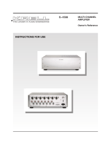
Figure 1 The Theater 7 Front Panel
Figure 2
Network Control
Screen
18
17
20
19
Front Panel
Back Panel
1 Power Button
Use this button to switch the
Theater 7 amplifier between
stand-by and operational modes.
2 Power Indicator
The stand-by indicator
illuminates red when
the Theater 7 ampli fier
is plugged into a standard AC
wall receptacle and the rear
panel power breaker switch is
in the up position. This
indicates that the amplifier is
in the stand-by mode and
ready to be switched to the
operational mode. The
indicator illuminates blue
when the Theater 7 amplifier
is in operational mode.
3 Front Panel Display
The front panel display shows the
model number, firmware version
,
serial number, and IP address.
Fault conditions are also displayed
on the front panel display.
After connecting the Theater 7
amplifier to a local area network
(LAN) via the RJ 45 connector (17),
enter the amplifier's IP address into
the address bar of a web browser
on a device connected to the same
LAN. The following additional
features are now available.
1 Temperature Monitoring
The Theater 7 monitors
the temperature of the
heat sink and adjusts fan
speed to maintain proper
cooling. Temperatures shown
in green, yellow, and red,
indicate cool, warm, and
hot operating temperatures.
2 Fan Operation Status
Fan speed is monitored
and is indicated by a
green OK for proper
operation and a red E
for an error.
3 Display Window
Indicates amplifier stat
us
and any fault conditions.
4 Software Update
Press this button to
initiate a software update
5 Error Log
Set to Enabled to have
fault conditions sent to
the e-mail addresses
listed in the e-mail
address window (6).
Network
Control
1
2 3 4
9
8
7
5
6
Figure 3 The Theater 7 Back Panel
6 E-mail Address window
Up to 3 e-mail addresses
can entered to receive
fault condition e-mails.
7 Display Timeout
Set the time for how long
the front panel
display
remains illuminated. The
Disabled option keeps
the display illuminated
indefinitely.
8 No Signal Timer
Set the time for how
long
the amplifier remains in
operational mode without
receiving an input signal.
The Disabled option
keeps the amplifier
in operational mode
indefinitely.
Note:
The
network must have
Internet access for features
4 and 5 to function.
14 Loudspeaker Outputs
The Theater 7 amplifier is equipped
with st
andard binding posts for
each amplifier channel.
15 Balanced Analog Inputs
The Theater 7 amplifier is equipped
with on
e balanced input per
channel via XLR connector.
16 Single-Ended Analog Inputs
The Theater 7 amplifier is equipped
with one single-ended input per
channel via RCA connector.
17 Ethernet Connection
18 12 VDC In (12 V trigger)
The 12 V Trigger input allows you
to place the Theater 7 amplifier into
the stand-by or operational mode
from other components.
19 IEC Connector
The connector is for use with the
provided IEC standard 20
amp
power cord. This connector and
power cord must remain
unobstructed for easy removal in
case of emergency.
20 AC Power Switch
Use this switch to change the
Theater 7
amplifier from off to the
stand-by mode.
9 Power Button
Click on the Power button
to turn the Theater 7 on
or off.
12V IN
KRELL INDUSTRIES, LLC.WWW.KRELLONLINE.COM
NO USER SERVICEABLE PARTS INSIDE.
RIGHT
CHANNEL
RIGHT SURR.
CHANNEL
RIGHT BACK
CHANNEL
CENTER
CHANNEL
LEFT BACK
CHANNEL
LEFT SURR.
CHANNEL
LEFT
CHANNEL
MADE IN U.S.A.
THEATER 7 AMPLIFIER
14
15
16
The RJ45 connector is used to
connect the Theater 7 ampli
fier to a
local area network (LAN). Once the
amplifier is connected to the LAN,
the amplifier’s network control
screen is viewable with a web
browser on a device connected to
the same network. Output current,
fan speeds, and temperature are all
monitored in real time. If a fault
occurs, it is displayed on the front
panel and on the web browser
interface. Additionally, if the LAN
has Internet access, e-mails will
automatically be sent to as many
as three e-mail addresses to notify
Krell, the end user and/or the
dealer of the condition.
This product is manufactured in the United States of America. Krell
®
is a registered trademark of Krell Industries, LLC.,
and is restricted
for
use by Krell Industries, LLC. its subsidiaries, and authorized agents. Krell Current Mode™, iBias™ and CAST™ is a trademark of Krell
Industries, LLC. All other trademarks and trade names are registered to their respective companies.
© 2017 by Krell Industries, LLC., All rights reserved
/