Page is loading ...

PRIMO
ZERO FEEDBACK FULLY BALANCED VALVE PRE-AMPLIFIER
INSTRUCTION MANUAL
Thank you for purchasing the Musical Fidelity Primo Valve Preamplifier.
This preamplifier uses our top quality, finely tuned balanced valve preamplifier circuits to deliver the absolute best in audio quality with no
listener fatigue, or transistor harshness. In addition there is no global feedback which reduces feedback related artefacts in the music.
The unit features five fully balanced signal inputs, which allow direct connection to balanced sources and outputs for the ultimate in dynamic
range and low-noise performance. The power supply and associated mains transformer are screened off in a mu-metal enclosure to isolate
the sensitive preamplifier circuits from mains noise and interference
This results in an astounding improvement in musicality and tonal neutrality and visually pleasing setup
Ease of use is augmented by the unit producing a trigger output to switch on any amplifier which accepts 5-12V trigger input, as well as
trigger input which will automatically allow the preamp itself to be controlled from a trigger source.
The Primo Valve Preamplifier is designed to be partnered with all current and future AMS and TITAN products, connecting directly
balanced inputs The Primo Valve Preamplifier is a perfect preamplifier for the 550K or 750K superchargers, and was designed with this in
mind. It can be connected to the line level inputs of the Superchargers (or, recommended, the XLR input on the 750K) as a normal
preamplifier. This combination yields one of the best amplification systems available at any price.
Used properly and carefully, it should give many years of outstanding musical reproduction.
Dust regularly with a soft duster or soft brush, but be careful when using cleaning or polishing agents - they may harm the surface finish.
If you have any questions about your audio system,
Please consult your dealer who is there to help and advise.

PRIMO Preamplifier CONTENTS
Issue 2
PAGE Section
3
Safety information
-
-
Mains plug (U.K. only)
Modification warning
4 General advice
-
-
Installation precautions
User information
5 Disposal information
EU disposal information
6 Installation
-
-
-
-
Introduction
Cleaning
Installation
Audio connection
7
Facilities and connections
-
Main unit front & rear panels
8 Remote control
- Operation and illustration
9
Operation
-
Starting, Volume, Mute, Phono, CD,
TUNER, AUX/HT, TAPE, Recording
10 Problems?
- Basic amplifier fault finding
11 Specifications
12 Manual history
Page 2 of 12

PRIMO Preamplifier SAFETY INFORMATION
Issue 2
IMPORTANT! (U.K. only)
This unit is supplied in the U.K. with mains lead fitted with a moulded 13 amp plug. If, for any reason, it is necessary
to remove the plug, please remove the fuse holder and dispose of the plug safely, out of reach of children.
It must not be plugged into a mains outlet.
The wires in the mains lead supplied with this appliance are coloured in accordance with the following code:
Green and yellow..............Earth
Blue................................Neutral
Brown.................................Live
WARNING - This appliance MUST be earthed
As the colours of the wires of the mains lead of this appliance may not correspond with the
coloured markings identifying the terminals in the plug, proceed as follows:
The wire which is coloured green-and-yellow must be connected to the terminal in the plug which is marked with the
letter E or coloured green or green-and-yellow, or by the earth symbol :
The wire which is coloured brown must be connected to the terminal which is marked with the letter L or coloured red.
The wire which is coloured blue must be connected to the terminal which is marked with the letter N or coloured black.
If connecting to a BS1363 plug, a 13 amp fuse must be used.
WARNING:
ANY MODIFICATIONS TO THIS PRODUCT NOT EXPRESSLY APPROVED
BY MUSICAL FIDELITY WHO IS THE PARTY RESPONSIBLE FOR
STANDARDS COMPLIANCE COULD VOID THE USER'S AUTHORITY TO
OPERATE THIS EQUIPMENT.
Page 3 of 12

PRIMO Preamplifier GENERAL ADVICE
Issue 2
INSTALLATION PRECAUTIONS & USER INFORMATION
This new Primo Valve Preamplifier is designed and built to provide trouble-free performance, but as with all electronic
devices it is necessary to observe a few precautions:
Heed all warnings shown on the back of the product.
Only connect the Primo Valve Preamplifier to a mains outlet having the same voltage as marked at the back of
the unit.
Always ensure that when disconnecting and reconnecting your audio equipment the mains supply is switched
off.
Position the mains lead and signal interconnects where they are not likely to be walked on or trapped by items
placed on them.
Do not use near water, or place water-filled containers on the Primo, for example, a flower vase or potted
plants. If water does spill inside, immediately pull out the mains plug from the wall socket and inform
the dealer, who should then check the unit before further use. Entry of liquid into the Primo Valve
Preamplifier is dangerous, and may cause electric shock or fire hazard.
Do not place the unit near direct heat sources such as radiators, direct sunlight or other equipment.
Dust regularly with a soft cloth or soft brush but be careful when using cleaning or polishing agents - they may
harm the surface finish.
The electronics in modern hi-fi equipment is complex and may, therefore, be adversely affected or damaged by
lightning. For protection of the audio system during electrical storms, remove the mains plugs and disconnect any
aerial lead.
If after-sales service is required, to help the dealer identify the Primo Valve Preamplifier please quote the serial number
located on the rear panel of the unit.
DANGER!
HIGH VOLTAGE
Do not remove any covers or try to gain access to the inside. The voltages contained within can
cause death or serious injury. There are no internal user adjustments or fuses to replace. All
service work MUST be referred to an authorised Musical Fidelity agent.
Note: Unauthorised opening of the equipment will invalidate any warranty claim.
Page 4 of 12

PRIMO Preamplifier DISPOSAL INFORMATION
Issue 2
DISPOSAL
Page 5 of 12
The
crossed out wheeled bin label that appears on the
back panel of the product indicates that the product must not be
disposed of as normal household waste. To prevent possible harm
to the environment please separate the product from other waste to
ensure that it can be recycled in an environmentally safe manner.
Please contact local government office or retailer for available
collection facilities.
DISPOSITION
La poubelle sur roulettes barrées X, qui apparaît en logo
sur le panneau arrière du produit, indique que celui-ci ne doit pas
être traité comme un déchet domestique commun. Afin de protéger
l'environnement, ce produit électronique devra être géré
séparément et donc recyclé selon les nouvelles normes
Européennes Rohs concernant les déchets d'appareils électroniques.
Prière de contacter les services concernés gouvernementaux ou
votre point de vente pour l'élimination et l'enlèvement de déchets
électroniques équipés de composants électroniques.
DISPOSAL
La etiqueta cruzada hacia fuera del compartimiento que
aparece en el panel trasero del producto indica que el producto no
se debe reciclarse como basura normal de la casa. Para prevenir
daños posible al ambiente separe por favor el producto de otras
basura para asegurarse de que puede ser reciclada de una manera
ambientalmente segura. Entre en contacto por favor a su oficina
gubernamental local o a su minorista para las instalaciones
disponibles de la colección.
RIFIUTI
L'etichetta del cassonetto barrato riportato sul retro
dell'apparecchio indica che il prodotto non deve essere smaltito
tramite la procedura normale di smaltimento dei rifiuti domestici.
Per evitare eventuali danni all'ambiente, separare questo prodotto
da altri rifiuti domestici in modo che possa venire riciclato in base
alle procedure di rispetto ambientale. Per maggiori dettagli
sulle aree di raccolta disponibili, contattate l'ufficio govenativo
locale od il rivenditore del prodotto.
FACHGERECHTE ENTSORGUNG:
Das auf der Geräterückseite angebrachte Label deutet
darauf hin, dass das Produkt nicht mit konventionellem
Hauskehricht entsorgt werden darf. Um Schäden und
Verschmutzungen an Umwelt und Mensch zu vermeiden, muss das
Produkt fachgerecht entsorgt und von anderem Abfall getrennt
werden. Wenden Sie sich bei Fragen hierzu an Ihren Fachhändler
oder an eine öffentliche Informationsstelle.
AFVAL
Het label op de achterzijde
van dit apparaat, een
afvalbak op wielen met een kruis doorgehaald, geeft aan dat dit
apparaat niet samen met gewoon huishoudafval mag worden
weggegooid. Om mogelijke schade aan onze leefomgeving te
voorkomen dient dit apparaat, gescheiden van gewoon
huishoudelijk afval, te worden afgevoerd zodat het op een
milieuvriendelijke manier kan worden gerecycled. Neem voor
beschikbare inzamelplaatsen contact op met uw gemeentelijke
reinigingsdien
st
of met uw elektronica leverancier.
HÄVITTÄMINEN
Yliruksattua jäteastiaa kuvaava tarra tuotteen
takalevyssä kertoo, että tuotetta ei saa käsitellä normaalina
talousjätteenä. Ympäristön suojelemiseksi on tuote pidettävä
erillään muusta jätteestä ja se on kierrätettävä ekologisesti
kestävällä tavalla. Ota yhteyttä laitteen myyjään tai Pirkanmaan
Ympäristökeskukseen lähimmän kierrätyskeskuksen löytämiseksi.
AFSKAFNING
Logoet med en skraldespand med kryds over på bagsiden
af apparatet indikerer at dette produkt ikke må kasseres som normal
husholdningsaffald. For at forebygge mulig skade på miljøet, bedes
De separere dette produkt fra andet affald, og sikre at det bliver
genbrugt på en miljørigtig måde. Kontakt venligst de lokale
myndigheder eller din forhandler for oplysning om nærmeste
tilgængelige opsamlingssted for elektronikaffald.
ΔΙΑΔΙΚΑΣΙΑ ΑΠΟΡ
ΡΙΨΗΣ
ΤΟ ΣΗΜΑ ΜΕ ΤΟΝ ΔΙΑΓΕΓΡΑΜΜΕΝΟ
ΤΡΟΧΗΛΑΤΟ ΚΑΔΟ ΑΠΟΡΡΙΜΑΤΩΝ ΣΤΗΝ ΠΙΣΩ ΟΨΗ ΤΟΥ
ΜΗΧΑΝΗΜΑΤΟΣ
ΔΗΛΩΝΕ
Ι ΟΤΙ ΤΟ ΠΡΟΙΟΝ ΑΥΤΟ ΔΕΝ ΠΡΕΠΕΙ ΝΑ
ΔΙΑΧΕΙΡΙΣΘΕΙ ΣΑΝ ΣΥΝΗΘΙΣΜΕΝΟ ΟΙΚΙΑΚΟ ΑΠΟΒΛΗΤΟ.
ΠΡΟΣ ΑΠΟΦΥΓΗ ΕΝΔΕΧΟΜΕΝΗΣ ΕΠΙΒΑΡΥΝΣΗΣ ΤΟΥ
ΠΕΡΙΒΑΛΛΟΝΤΟΣ, ΞΕΧΩΡΙΣΤΕ ΤΟ ΠΡΟΙΟΝ ΑΠΟ ΤΑ ΑΛΛΑ
ΑΠΟΡΡΙΜΑΤΑ ΩΣΤΕ ΝΑ ΕΞΑΣΦΑΛΙΣΘΕΙ Η ΑΝΑΚΥΚΛΩΣΗ
ΤΟΥ ΜΕ ΤΟΝ ΠΡΕΠΟΝΤΑ ΤΡΟΠΟ.
ΠΑΡΑΚΑΛΟΥΜΕ ΝΑ ΕΠΙΚΟΙΝΩ
ΝΗΣΕΤΕ ΜΕ ΤΗΝ ΤΟΠΙΚΗ
ΥΠΗΡΕΣΙΑ ΑΝΑΚΥΚΛΩΣΗΣ Η ΜΕ ΤΟ ΚΑΤΑΣΤΗΜΑ
ΑΓΟΡΑΣ ΓΙΑ ΠΕΡΙΣΣΟΤΕΡΕΣ ΛΕΠΤΟΜΕΡΕΙΕΣ.

PRIMO Preamplifier INSTALLATION
Issue 2
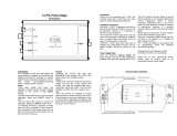
INTRODUCTION
Congratulations on the purchase of the new Primo Valve
Preamplifier. The Primo is entirely valve based, with
fully balanced and single ended signal paths from input
via fully balanced input switches and balanced volume
control right the way through to the balanced and single
ended outputs.
It is recommended that, to obtain the best performance,
the balanced features are used, to keep noise and
interference to an absolute minimum, inherently
allowing 6dB more headroom within the circuitry.
The single-ended side features our finely tuned and
tweaked valve preamplifier circuits, for smooth sound
coupled with low noise and virtually no distortion.
Great attention has been paid to internal layout,
isolating each circuit section to prevent possible
interaction.
The resultant performance achieved by this unit is
among the best in the world. It has excellent signal to
noise ratio, low distortion, wide bandwidth and dynamic
range, with extraordinary resolution and fine detail.
CLEANING
Before cleaning the units, switch off power at the mains
switch and remove the mains plug from the wall socket.
Clean the cabinets and remote control unit using a moist
cloth. Using solvents, white spirit or thinners is not
advised, as they could damage the surface finish.
INSTALLATION
Position the Primo Valve Preamplifier on a stable,
horizontal surface where there is no risk of it being
knocked, or subjected to vibration such as from
loudspeakers. This is of particular importance for the
Primo, as all valves can be prone to some “microphony”
and this could result in undesired feedback artefacts in
the signal.
The Primo also features a high input impedance circuit
which is very
sensitive. Keep all mains and power
supply leads well away from the input leads and sockets,
and keep the input leads as far apart from each other as
possible to avoid any crosstalk. Unconnected
inputs may
experience a certain amount of signal bleed through
from adjacent connected
inputs. This is normal for high
input impedance, and does not indicate a fault.
POWER CONNECTIONS
The Primo Valve Preamplifier is supplied with a
standard IEC mains cable which plugs into the IEC
socket at the back of the preamplifier.
AUDIO CONNECTIONS
Inputs: Connect all sources to relevant input RCA or
XLR sockets (see p.7 For more information).
Use good quality fully connected (signal and ground)
coaxial phono cables for all RCA signal connections.
Fully balanced inputs (XLR) are available for
connecting to suitable components. For these, we
recommend any good quality straight-through connected
balanced cables.
Outputs: Connect power amplifier(s) to the RCA
sockets on the back panel marked as LEFT and RIGHT
outputs
Fully balanced outputs are available for connecting to
suitable components. For these, we recommend any
good quality straight-through balanced cables
The TAPE output allows loop through of selected
source signals for example, to pass on to recorder or
monitor. It is also the ideal output to connect our
headphone amps into.
Page 6 of 12

PRIMO Preamplifier FACILITIES AND CONNECTIONS
Issue 2
Primo FRONT PANEL
1 2 3 4 5 6
1. ON/STANDBY Button
2. IR RECIEVER lens
3. GAIN button
4. TAPE MONITOR button
5. VOLUME control
6. INPUT selector buttons
Primo REAR PANEL
7 8 9 10 11 12 13 14 15 16 17 18
19 20 21 22 23 24 25 26 27 28
7. MAIN OUTPUT RCA sockets
8. TAPE RCA input sockets
9. TAPE Input type selector switch
10. AUX 2 RCA input sockets
11. AUX 2 Input type selector switch
12. TAPE OUTPUT RCA sockets
13. AUX 1 RCA input sockets
14. AUX 1 Input type selector switch
15. TUNER RCA input sockets
16. TUNER Input type selector switch
17. CD RCA input sockets
18. CD Input type selector switch
19. MAIN OUTPUT XLR sockets
20. TAPE XLR input sockets
21. AUX 2 XLR input sockets
22. TRIGGER IN 3.5mm (mono) socket
23. POWER INPUT IEC from mains
supply
24. TRIGGER OUT 3.5mm (mono)
socket
25. MAINS ON/OFF switch
26. AUX 1 XLR input sockets
27. TUNER XLR input sockets
28. CD XLR input sockets
XLR Balanced input and output lead connections:
(for reference only, no XLR signal leads supplied)
Pin functions:
1 Ground (cable shield)
2 Normal polarity ("hot" or “+”)
3 Inverted polarity ("cold" or “-“)
Page 7 of 12

PRIMO Preamplifier REMOTE CONTROL
Issue 2
Remote control Handset (supplied with the battery already installed).
The Primo remote control shown below enables functions from this unit to be operated from a convenient distance.
Equivalent buttons on the remote control have the same functions as those on the front panel of the unit. Other
functions are only available by remote control.
As the handset uses an invisible infra-red light beam, the front edge must be pointed directly towards the receiver
window at the front of the player, without visual obstruction between them.
For reliable remote control operation, the Primo Preamplifier should also be positioned so that direct sunlight,
fluorescent or other bright lights do not fall directly on the IR receiver lens (see P.7). Such light can interfere with
remote control operation and/ or maximum operating range.
If the range of the remote control greatly decreases, replace the battery, Lithium button type CR2450.
Please dispose of used batteries in accordance to local regulations.
Changing the Battery
If the remote fails to operate the Primo
functions correctly, or a substantial
reduction in range is observed, the
battery may be exhausted.
1. Remove the six screws in the base of
the remote control.
2. Remove the base to gain access to the
battery holder in the bottom left of the
remote.
3. Gently Lift the spent battery from the
holder.
4. Discard the spent battery according to
local regulations.
5. Replace with a new CR2450 Lithium
battery.
If there are any problems with changing
the battery please contact the dealer for
assistance.
RC5 codes used by this remote control
HEX DECIMAL
SYSTEM
CODE FOR
PREAMP
10 16
POWER
0C 12
MUTE
0D 13
VOLUME ▲
10 16
VOLUME ▼
11 17
GAIN
22 34
CD
01 1
TUNER
02 2
AUX 1
03 3
AUX 2
04 4
TAPE
05 5
POWER – Switches unit to
standby mode.
MUTE – Mutes outputs
until pressed again
VOLUME ▲ – increases
volume
VOLUME ▼ – decreases
volume
GAIN – Selects overall
gain
CD – Selects CD input
TUNER – Selects TUNER
input
AUX 1 – Selects AUX 1
input
AUX 2 – Selects AUX 2
input
TAPE – Select TAPE input
Important notice- The remote control supplied is expensively machined from solid aluminium.
Please take great care of this remote control as it would be costly to replace.
Page 8 of 12

PRIMO Preamplifier OPERATION
Issue 2
Page 9 of 12
STARTING
For all the inputs, there is a switch which selects the type of
input being used (see P.7).
Each switch must be set according to the sockets being used.
For an input using the RCA input sockets the switch should
be in the RCA (up) position.
For an input using XLR, the corresponding switch must be
set to XLR (down) position.
Once all connections are made, switch on the unit, using the
POWER switch on the back of the unit. The standby LED
will light on the front panel. Push the ON/STANDBY button,
and the POWER and MUTE LEDs will light. Outputs are
muted, for about forty-five seconds, so no sound will be heard
until the MUTE LED goes out. The unit is now warmed up
and settled, ready for use.
VOLUME
The volume should be adjusted for normal listening levels.
This is done by turning the volume control up or down on the
front panel. The volume level is readily identifiable on the
dial for reference.
Adjusting the volume can also be achieved using the remote
handset, using the volume up/down buttons (see p. 8).
GAIN
The gain is used to correctly set the amplification factor of
single ended mode (RCA) and balanced (XLR) inputs. Select
input that is to be used in single ended mode. Press GAIN
button so LED above is alight for input using single ended
source.
The unit is designed to remember which inputs are set and
which are not, even when unplugged. To “un-set” an input,
simply select that input, and push the GAIN button again, to
extinguish the LED.
Selecting the input GAIN can also be achieved using the
corresponding button on the remote handset, (see p. 8) The
remote GAIN button must be held in for about 3 seconds to
enable/disable the additional gain. This is a design feature, to
prevent accidental activation/deactivation. The front panel
button operates normally.
Maximum Gain
Input and output
LED ON LED OFF
Balanced in and out 18dB 12dB
Single ended in balanced out 18dB 12dB
Single ended in and out 12dB 6dB
Balanced in single ended out 12dB 6dB
MUTE (remote only)
The sound from the preamplifier may be muted by use of the
MUTE button on the remote. Press once and MUTE LED
will light indicating muted state. No sound will be heard from
the speakers.
To return to listening; simply press the MUTE button again
so MUTE LED is no longer lit.
CD
To use the CD input, connect CD player outputs to the CD
input RCA or XLR sockets (see p.7). Select CD input using
the CD source button so the LED above is lit.
Selecting the CD input can also be achieved using the
corresponding button on the remote handset, (see p. 8).
TUNER
To use the TUNER input, connect TUNER outputs to the
TUNER input RCA or XLR sockets (see p.7). Select TUNER
input using the TUNER source button so the LED above is lit.
Selecting the TUNER input can also be achieved using the
corresponding button on the remote handset, (see p. 8).
AUX1
To use the AUX1 input, connect source outputs to the AUX1
input RCA or XLR sockets (see p.7). Select AUX1 input using
the AUX1 source button so the LED above is lit.
Selecting the AUX1 input can also be achieved using the
corresponding button on the remote handset, (see p. 8).
AUX2
To use the AUX2 input, connect source outputs to the AUX2
input RCA or XLR sockets (see p.7). Select AUX2 input using
the AUX2 source button so the LED above is lit.
Selecting the AUX2 input can also be achieved using the
corresponding button on the remote handset, (see p. 8).
TAPE
To use the TAPE input, connect source outputs to the TAPE
input RCA or XLR sockets (see p.7). Select TAPE input using
the TAPE source button so the LED above is lit.
Selecting the TAPE input can also be achieved using the
corresponding button on the remote handset, (see p.8)
RECORDING AND TAPE MONITOR
To record to tape, (or alternatively CD recorder, DAT,
minidisk or computer soundcard analogue input) connect the
tape out to the recorder line in. Press the input selector button
on the front panel or remote control. This source will now be
routed to the Primo Valve Preamplifier TAPE OUT, without
any changes, for recording by tape deck.
The recording can be directly monitored through the
loudspeakers by pressing the TAPE MONITOR button. Press
again to return back to the input being recorded.
On some 3 head tape decks there is an additional tape/source
switch which should be in the tape position for this to work. If
in doubt, please consult tape deck operating manual.
Note - adjustment of the volume control has no effect on the
recording level.
TRIGGER input and output
The trigger input allows the preamplifier to be switched on by
another device supplying between 5-12VDC trigger output.
The trigger signal can be either polarity, + or –, but must be
between 5 and 12V DC.
The trigger output allows the remote triggering of other units
that accept up to +12V DC trigger input. This includes our
AMS and TITAN power amplifiers. On our amplifiers the
trigger input automatically takes over the ON and
off
functions overriding the power amplifier ON/OFF button.
This trigger output also passes on the state of the trigger input.
This allows both the preamp and following unit to be
simultaneously controlled by an external trigger source.
Note
: Triggering will not override the MAINS on/off buttons.
If any of the apparatus does not trigger on check all MAINS
SWITCHE(S) are set to ON

PRIMO Preamplifier
PROBLEMS?
Issue 2
Page 10 of 12
Basic problem-solving with an amplifier is similar to troubleshooting other electrical or electronic equipment. Always
check the most obvious possible causes first, such as the following examples:
Problem Probable Cause Remedy
No power when POWER button is
pressed
Unit(s) not coming on by trigger
signal
Mains power plug is not fully inserted
into rear socket or mains socket
Mains to unit(s) switched off
Trigger signal too weak or not present
Trigger leads disconnected or faulty
Plug in securely.
Check all units to be triggered have
their MAINS SWITCHES set to ON
The trigger will not work with them
in the off position
Check Trigger signal, and trigger
sending unit
Check Trigger lead(s)
No sound Mute function is still active
Wrong connections between input
sources and the unit
Volume turned down
Press the MUTE button on the
remote control to cancel.
Check audio input lead connections
and correct source is selected
Check volume level
Sound cut(s) out Loose connection
Check input and output connections
When all has been double-checked
reduce volume and switch unit back
on.
Hum Audio connector plug not fully
pushed in
Incorrect input switch position
Cable Fault
Unsuitable Cable
(e.g. cable grounds not connected)
Insert plug securely
Check cable is connected at both
ends.
Check the corresponding input switch
is correctly set for RCA or XLR input
N.B. Some esoteric cables have
internal wiring intentionally
disconnected/modified. For best
results on all inputs, please use good
quality screened coax; signal and
screens both separately connected at
both ends.
No audio output, or too low level
output
Incorrect or missing connections Check connections and make sure
they are secure.
Remote control does not work Amplifier’s POWER switch is set to
off
Battery fitted the wrong way round
Battery is flat
Remote control is not pointed directly
towards the front panel of the
amplifier
Interference from another source
Set switch to on
Insert battery correctly
Change battery for a new one
Ensure there is no obstruction
between the remote control and
amplifier front.
Lighting such as fluorescent,
incandescent, or even sunlight
contains large amounts of infra red
radiation. Ensure such sources are not
shining directly on the infra red
window as this could swamp the
signal from the remote control.
Also check the system and any other
nearby remotes for stuck buttons
Remote control range has greatly
reduced
Battery is running out Change battery for a new one.
If none of these actions affect a cure, please contact the dealer, or an authorised Musical Fidelity service agent.
Remember; never open the case of the Primo, as this will invalidate the guarantee.

PRIMO Preamplifier
SPECIFICATIONS
Issue 2
Page 11 of 12
Specification: Maximum Output Voltage 32Vrms
Output impedance 600 ohms
THD + N, 20Hz to 20 kHz 0.0035% typical
Signal / noise ratio >119dB
Input sensitivity for full
output
8V
Input impedance 150K ohms CT (centre-tapped)
Overload margin 30dB
Channel separation 105dB
Frequency response 5Hz- 50KHz -0.5dB
Power requirement: 115/230V (factory preset)
or 100V only
120 W maximum (operating)
<20W (standby)
Connections:
(Main unit)
Line level inputs 5 pairs line level RCA connectors
5 pairs XLR (female) balanced line level inputs
Line level outputs 1 pair RCA preamp line outputs (level controlled by volume)
1 pair XLR (male) balanced outputs
Tape outputs 1 pair RCA tape line outputs (fixed level)
Trigger Input 3.5mm mono jack socket ±5 to ±12V
Trigger Output 3.5mm mono jack socket +5 to +12V (tip +, sleeve -)
Power input: 3 pin IEC from mains
Accessories: Mains lead 10 Amp IEC type 1 off
Remote control PRIMO Preamplifier remote control 1 off
Batteries Size CR2450, Lithium button type 1 off (supplied, fitted)
Dimensions: Unit only
483mm 19 Inches Wide
150mm 6 Inches High inc. feet
410mm 16¼ Inches Deep inc. volume control and rear panel sockets
Weight: 16.8kg, 37lbs
Dimensions: Unit in shipping carton
695mm 27⅓ inches
610mm 24 inches
385mm 15⅛ inches
Weight: 22kg, 44½lbs
Musical Fidelity reserves the right to make improvements which may result in specification or feature
changes without notice.

PRIMO Preamplifier
MANUAL REVISION
Issue 2
RELEASE DATE CHANGES
Issue 1 11
th
March 2009 1
st
issue
Issue 2 25
th
January 2011 Gain table added P.9
Page 12 of 12
/


