Page is loading ...

DYNATEMP
®
INSTALLATION, OPERATION,
AND SERVICE MANUAL
DynaTemp
®
Manual • Rev A • 07610-004-29-29 • Issued: 07-27-2016 • Revised: N/A
DYNATEMP
®
SERIES DOOR-TYPE DISHMACHINES


MANUFACTURER'S WARRANTY
ONE YEAR LIMITED PARTS AND LABOR WARRANTY
ALL NEW JACKSON DISHWASHERS ARE WARRANTED TO THE ORIGINAL PURCHASER TO BE FREE FROM DEFECTS IN
MATERIAL OR WORKMANSHIP, UNDER NORMAL USE AND OPERATION, FOR A PERIOD OF (1) ONE YEAR FROM DATE OF
PURCHASE, BUT IN NO EVENT TO EXCEED (18) EIGHTEEN MONTHS FROM DATE OF SHIPMENT FROM THE FACTORY.
Jackson WWS agrees under this warranty to repair or replace, at its discretion, any original part which fails under normal use
due to faulty material or workmanship during the warranty period, providing the equipment has been unaltered, and has been
properly installed, maintained, and operated in accordance with the applicable factory instruction manual and failure is reported
to an authorized service agency within the warranty period. This includes the use of factory-specied genuine replacement parts,
purchased directly from a Jackson-authorized parts distributor or service agency. Use of generic replacement parts may create a
hazard and void warranty certication.
The labor to repair or replace such failed part will be paid by Jackson WWS, within the continental United States, Hawaii, and Canada,
during the warranty period provided a Jackson WWS authorized service agency, or those having prior authorization from the factory,
performs the service. Any repair work by persons other than a Jackson WWS authorized service agency is the sole responsibility of
the customer. Labor coverage is limited to regular hourly rates; overtime premiums and emergency service charges will not be paid
by Jackson WWS.
Accessory components not installed by the factory carry a (1) one year parts warranty only. Accessory components such as table limit
switches, pre-rinse units, etc. that are shipped with the unit and installed at the site are included. Labor to repair or replace these
components is not covered by Jackson WWS.
This warranty is void if failure is a direct result from shipping, handling, re, water, accident, misuse, acts of God, attempted repair by
unauthorized persons, improper installation, if serial number has been removed or altered, or if unit is used for a purpose other than
originally intended.
TRAVEL LIMITATIONS
Jackson WWS limits warranty travel time to (2) two hours and mileage to (100) one-hundred miles. Jackson WWS will not pay for
travel time and mileage that exceeds this, or any additonal fees—such as those for air or boat travel—without prior authorization.
WARRANTY REGISTRATION
To register your product, go to www.jacksonwws.com or call 1-888-800-5672. Failure to register your product will void the warranty.
REPLACEMENT PARTS WARRANTY
Jackson replacement parts are warranted for a period of (90) ninety days from date of installation or (180) one-hundred-eighty days
from the date of shipment from the factory, whichever occurs rst.
PRODUCT CHANGES AND UPDATES
Jackson WWS reserves the right to make changes in the design and specication of any equipment as engineering or necessity
requires.
THIS IS THE ENTIRE AND ONLY WARRANTY OF JACKSON WWS. JACKSON’S LIABILITY ON ANY CLAIM OF ANY KIND,
INCLUDING NEGLIGENCE, WITH RESPECT TO THE GOODS OR SERVICES COVERED HEREUNDER, SHALL IN NO CASE
EXCEED THE PRICE OF THE GOODS OR SERVICES OR PART THEREOF WHICH GIVES RISE TO THE CLAIM.
THERE ARE NO WARRANTIES, EXPRESSED OR IMPLIED, INCLUDING FOR FITNESS OR MERCHANTABILITY, THAT ARE
NOT SET FORTH HEREIN, OR THAT EXTEND BEYOND THE DURATION HEREOF. UNDER NO CIRCUMSTANCES WILL
JACKSON WWS BE LIABLE FOR ANY LOSS OR DAMAGE, DIRECT OR CONSEQUENTIAL, OR FOR DAMAGES IN THE
NATURE OF PENALTIES, ARISING OUT OF THE USE OR INABILITY TO USE ANY OF ITS PRODUCTS.
ITEMS NOT COVERED
THIS WARRANTY DOES NOT COVER CLEANING OR DELIMING OF THE UNIT OR ANY COMPONENT SUCH AS, BUT NOT
LIMITED TO, WASH ARMS, RINSE ARMS, OR STRAINERS, AT ANYTIME. NOR DOES IT COVER ADJUSTMENTS SUCH
AS, BUT NOT LIMITED TO, TIMER CAMS, THERMOSTATS, OR DOORS BEYOND (30) THIRTY DAYS FROM THE DATE OF
INSTALLATION. IN ADDITION, THE WARRANTY WILL ONLY COVER REPLACEMENT WEAR ITEMS SUCH AS CURTAINS,
DRAIN BALLS, DOOR GUIDES, OR GASKETS DURING THE FIRST (30) THIRTY DAYS AFTER INSTALLATION. ALSO,
NOT COVERED ARE CONDITIONS CAUSED BY THE USE OF INCORRECT (NON-COMMERICAL) GRADE DETERGENTS,
INCORRECT WATER TEMPERATURE OR PRESSURE, OR HARD WATER CONDITIONS.

i
Revision
Letter
Revision
Date
Made by Applicable ECNs Details
A 07-27-16 JH N/A Initial release of the manual.
REVISION HISTORY

ii
Model:
Serial No.:
Installation Date:
Service Rep. Name:
Phone Number:
NOMENCLATURE
Jackson WWS, Inc. provides
technical support for all of
the dishmachines detailed
in this manual. We strongly
recommend that you refer to
this manual before making a
call to our technical support
staff. Please have this manual
with you when you call so
that our staff can refer you, if
necessary, to the proper page.
Technical support is not
available on holidays.
Contact technical support toll
free at 1-888-800-5672.
Technical support is available
for service personnel only.
DynaTemp
®
Door-type dishmachine; electrically-heated, high-temp,
hot-water sanitizing, with booster heater.
DynaTemp
®
NB
Door-type dishmachine; electrically-heated, high-temp,
hot-water sanitizing, without booster heater.
DynaTemp
®
S
Door-type dishmachine; steam-heated, high-temp,
hot-water sanitizing.

iii
TABLE OF CONTENTS
SPECIFICATIONS
MACHINE DIMENSIONS 1
TABLE DIMENSIONS 2
OPERATING CAPACITIES 3
ELECTRICAL REQUIREMENTS 4
INSTALLATION/OPERATION INSTRUCTIONS
INSTALLATION INSTRUCTIONS 6
OPERATING INSTRUCTIONS 9
DETERGENT CONTROL 13
DELIMING INSTRUCTIONS 14
DISPLAY INSTRUCTIONS 15
MAINTENANCE
PREVENTATIVE MAINTENANCE 16
TROUBLESHOOTING
DISPLAY PROGRAMMING 17
FAULT CODES 19
COMMON PROBLEMS 22
DRAWING/PARTS SECTION
CONTROL BOX ASSEMBLY 24
HOOD ASSEMBLY 25
CANTILEVER ARM ASSEMBLY 26
TUB ASSEMBLY 28
STEAM TUB ASSEMBLY 30
STEAM COIL ASSEMBLY 32
FRAME ASSEMBLY 33
RINSE TANK ASSEMBLY 34
INCOMING/OUTLET PLUMBING ASSEMBLY 35
DYNATEMP NB INLET PLUMBING 37
INCOMING STEAM PLUMBING ASSEMBLIES 39
WASH MOTORS 41
MOTOR & PUMP ASSEMBLY 42
WASH HEATERS/RINSE HEATERS 43
DOOR INTERLOCK 44
DYNATEMP PLUMBING OPTIONS 45
SOLENOID VALVE & VACUUM BREAKER 46
WASH & RINSE ARM ASSEMBLIES 47
GO*BOX COMPONENTS 49
DRAIN QUENCH ASSEMBLY 50

iv
TABLE OF CONTENTS
SCHEMATICS
DYNATEMP 208/230V, 50/60 HZ, 1/3 PHASE 53
DYNATEMP 460/480V, 60 HZ, 3 PHASE 54
DYNATEMP S 208/230V, 50/60 HZ, 1/3 PHASE 55
SCHEMATIC OPTIONS
DRAIN QUENCH OPTION 56
ADDENDUM
PHASE CONVERSION KIT 57
DISPLAY TEMPLATE 58
EXHAUST FAN WIRING 59
SYMBOLS
!
CAUTION
!
WARNING
NOTICE
- risk of injury to personnel.
- risk of damage to equipment.
- risk of electrical shock.
- lockout electrical power.
- reference data plate.
- important note.
i
ABBREVIATIONS & ACRONYMS
ANSI - American National Standards Institute
GHT - Garden Hose Thread
GPM - Gallons per Minute
GPG - Grains per Gallon
HP - Horse Power
Hz - Hertz
ID - Inside Diameter
kW - Kilowatts
NEC - National Electrical Code
NFPA - National Fire Protection Association
NPT - National Pipe Thread
PSI - Pounds per Square Inch
V - Volts

1
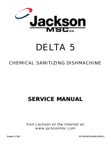
07610-004-29-29-A
LEGEND
A - DRAIN 1-1/2" NPT
B - WATER INLET 1/2" NPT
C - ELECTRICAL CONNECTION
D - DETERGENT CONNECTION
E - RINSE AID CONNECTION
All dimensions from the oor can be increased 2" using the machine's adjustable feet.
SPECIFICATIONS
DYNATEMP MACHINE DIMENSIONS
LEGEND
A-
DRAIN 1-1/2" IPS
B-WATER INLET 1/2" NPT
C-ELECTRICAL CONNECTION
All vertical dimensions are +/1 1/2" due to
adjustable bullet feet.
61 [1
54
9.4
0m
m
]
4
1 1/
2 [1054
.1
0mm
]
14
1
/2 [3
68.30m
m
]
9 11/16 [246.06mm]
10 1/8 [257.18mm]
C
B
A
25 5/8 [650
.8
8m
m]
30 5/16 [769.94mm]
1
5/16
[33.34m
m]
6 1/4 [158.75mm]
7 5/8 [1
93
.6
8m
m]
12 3/4 [323.85mm]
11 13/16 [300.04mm]
34 [86
3.60m
m
]
B
A
33 3/4 [857.25mm]
C
9
5/16 [236.54
mm
]
29 1/2 [749.3mm]
1
5/1
6
[33.34m
m]
6 1/4 [158.75mm]
D
E
81 [2057.4mm]
(with door open)

2
07610-004-29-29-A
SPECIFICATIONS
TABLE DIMENSIONS
20 1/2” (52.1 cm)
OPENING
25 1/4”
(64.1 cm)
20 1/2” (52.1 cm)
OPENING
25 1/4”
(64.1 cm)
2 1/2” (6.4 cm)
4” (10.2 cm)
MINIMUM
4” (10.2 cm)
MINIMUM
2 1/2”
(6.4 cm)
3/4” (1.9 cm)
20 1/2”
(52.1 cm)
1 1/2” (3.81 cm) ROLL
TABLE DIMENSIONS
CONNECTION TO DISHMACHINE
TABLE DIMENSIONS
CORNER INSTALLATION
4” (10.2 cm)
MINIMUM
2 1/2”
(6.4 cm)
25 1/4”
(64.1 cm)
20 1/2” (52.1 cm)
OPENING
25 1/4” (64.1 cm)
TABLE DIMENSIONS
STRAIGHT THROUGH INSTALLATION
DETAIL A
SCALE 1 / 5
A
5.00
5.38

3
07610-004-29-29-A
PERFORMANCE/CAPABILITIES
Operating Capacity:
Racks per Hour 57
Dishes per Hour 1450
Glasses per Hour 1450
Minimum Operating Cycle (seconds):
Cycle 1 Wash Time 40
Cycle 2 Wash Time 90
Cycle 3 Wash Time 220
Rinse Time 11
Dwell Time 7
Cycle 1 Total Time 58
Cycle 2 Total Time 108
Cycle 3 Total Time 238
Tank Capacity (gallons/liters):
Wash Tank 8.0/30.3
Rinse Tank 3.0/11.4
Steam Requirements:
Inlet Steam Connection (NPT) 3/4"
Steam Flow Pressure (PSI) 15-20
Consumption @ 15 PSI (lbs/hr) 45
Electrical Loads (as applicable):
Wash Motor HP 1
Wash Heater kW 5.4
Rinse Heater kW 14
OPERATING CAPACITIES
SPECIFICATIONS
WATER REQUIREMENTS
DynaTemp
®
Wash Temperature (Minimum) 150 °F/66 °C
Rinse Temperature (Minimum) 180 °F/83 °C
Inlet Water Temperature:
14 kW Rinse Heater 110 °F/44 °C
Flow Pressure (PSI) 10 ± 2
Water Line Size (NPT) 3/4”
Drain Line Size (NPT) 1 1/2”
DynaTemp
®
NB
Wash Temperature (Minimum) 150 °F/66 °C
Rinse Temperature (Minimum) 180 °F/83 °C
Inlet Water Temperature 180 °F/83 °C
Flow Pressure (PSI) 10 ± 2
Water Line Size (NPT) 3/4”
Drain Line Size (NPT) 1 1/2”
NOTE: Always refer to the machine data plate for specic electrical and water requirements.
The material provided on this page is for reference only and may change without notice.
NOTICE
i

4
07610-004-29-29-A
ELECTRICAL REQUIREMENTS
SPECIFICATIONS
Local codes may require more stringent protection than what is displayed here. Always verify with your electrical
service contractor that your circuit protection is adequate and meets all applicable national and local codes.
Numbers in this manual are for reference and may change without notice.
VOLTS PHASE HZ
RINSE HEATER
RATINGS
TOTAL
AMPS
TYPICAL
ELECTRICAL CIRCUIT
208 1 50 12 kW@240 V 71 A 90 A
208 1 50 14 kW@240 V 78 A 100 A
230 1 50 12 kW@240 V 78 A 100 A
230 1 50 14 kW@240 V 86 A 110 A
NOTE: Typical Electrical Circuit is based on:
1. 125% of the full amperage load of the machine.
2. Typical xed-trip circuit breaker sizes as listed in the NEC (Latest
Edition).
208 3 50 12 kW@240 V 45 A 60 A
208 3 50 14 kW@240 V 49 A 70 A
230 3 50 12 kW@240 V 48 A 60 A
230 3 50 14 kW@240 V 53 A 70 A
380 3 50 12 kW@380 V 29 A 40 A
380* 3 50 14 kW@240 V 34 A 45 A
415 3 50 12 kW@415 V 26 A 35 A
415 3 50 14 kW@415 V 29 A 40 A
440 3 50 12 kW@460 V 21 A 30 A
440 3 50 14 kW@460 V 25 A 35 A
208 1 60 12 kW@240 V 69 A 90 A
208 1 60 14 kW@240 V 76 A 100 A
230 1 60 12 kW@240 V 76 A 100 A
230 1 60 14 kW@240 V 84 A 110 A
208 3 60 12 kW@240 V 43 A 60 A
208 3 60 14 kW@240 V 47 A 60 A
230 3 60 12 kW@240 V 46 A 60 A
230 3 60 14 kW@240 V 51 A 70 A
460 3 60 12 kW@480 V 22 A 30 A
460 3 60 14 kW@480 V 25 A 35 A
* This model is wired in a wye conguration for the heaters.
NOTICE
i

5
07610-004-29-29-A
ELECTRICAL REQUIREMENTS
INSTALLATION
VOLTS PHASE Hz
RINSE HEATER
RATINGS
TOTAL
AMPS
TYPICAL
ELECTRICAL CIRCUIT
208 1 50 N/A 28 A 35 A
230 1 50 N/A 35 A 45 A
DynaTemp NB Electrical Characteristics:
208 3 50 N/A 20 A 25 A
230 3 50 N/A 21 A 30 A
380 3 50 N/A 10 A 15 A
415 3 50 N/A 10 A 15 A
440 3 50 N/A 8 A 15 A
208 1 60 N/A 26 A 35 A
230 1 60 N/A 28 A 35 A
208 1 60 N/A 26 A 35 A
230 1 60 N/A 28 A 35 A
208 3 60 N/A 18 A 25 A
230 3 60 N/A 28 A 35 A
460 3 60 N/A 8 A 15 A
DynaTemp S Electrical Characteristics:
VOLTS PHASE Hz
RINSE HEATER
RATINGS
TOTAL
AMPS
TYPICAL
ELECTRICAL CIRCUIT
208 1 60 N/A 6 A 15 A
230 1 60 N/A 6 A 15 A
208 3 60 N/A 6 A 15 A
230 3 60 N/A 6 A 15 A
i
i

6
07610-004-29-29-A
INSTRUCTIONS
INSTALLATION
Before installing the unit, check the packaging and machine for damage. If the
packaging is damaged, the machine might also be damaged. If there is damage to
both the packaging and machine, do not throw away the packaging. The dishmachine
has been inspected and packed at the factory and is expected to arrive to you in new,
undamaged condition. However, rough handling by carriers or others might result in
damage to the unit while in transit. If so, do not return the unit to the manufacturer;
instead, contact the carrier and ask them to send a representative to the site to inspect
the damage and complete an inspection report. You must contact the carrier within 48
hours of receiving the machine. Also contact the dealer that sold you the unit.
While removing the machine from the container, ensure that there are no missing parts.
If an item is missing, contact the manufacturer immediately.
The dishmachine must be level in its operating location to prevent
damage to the machine during operation and to ensure the best
results. The unit comes with four adjustable bullet feet, which can
be turned using a pair of channel locks (or by hand if the unit can
be raised safely). Ensure that the unit is level from side-to-side and
front-to-back before making any connections.
Plumbing connections must comply with all applicable local, state, and national
plumbing codes. The plumber is responsible for ensuring that the incoming water line
is thoroughly ushed before connecting it to any component of the dishmachine. It is
very important to remove all foreign debris from the water line that might potentially get
trapped in the valves or cause an obstruction. Any valves that are fouled as a result of
foreign matter left in the water line—and any expenses resulting from this fouling—are
not the responsibility of the manufacturer.
The drains for the DynaTemp models covered in this manual are gravity discharge
drains. All piping from the 1 1/2” FNPT connection on the wash tank must be pitched
1/4” per foot to the oor or sink drain. All piping from the machine to the drain must be a
minimum 1 1/2” NPT and must not be reduced. There must also be an air gap between
the machine drain line and the oor sink or drain. If a grease trap is required by code, it
should have a ow capacity of 5 gallons per minute (GPM). For units equipped with the
Drain Quench Option, see the Drain Quench Assembly section of this manual.
VISUAL INSPECTION
LEVEL THE
DISHMACHINE
UNPACKING THE
MACHINE
PLUMBING THE
DISHMACHINE
CONNECTING THE
DRAIN LINE
Do not throw away the
container if damage is
evident!
The plumber MUST ush
the incoming water line!

7
07610-004-29-29-A
INSTRUCTIONS
INSTALLATION
Take care not to confuse
static pressure with
ow pressure!
PLUMBING
CHECK
NOTE: Ensure that you have read the section entitled “PLUMBING THE
DISHMACHINE” on the previous page before proceeding.
Install the water supply line (1/2” ID minimum) to the dishmachine line strainer using
copper pipe. It is recommended that a water shut-off valve be installed in the water
line between the main supply and the machine to allow access for service. For units
equipped with the Drain Quench Option, see the Drain Quench Assembly section of
this manual.
The water supply line is to be capable of 10 ± 2 pounds per square inch (PSI) “ow”
pressure at the recommended temperature indicated on the data plate.
The manufacturer recommends the installation of a water pressure regulator* in the
incoming water line of all DynaTemp models to ensure proper owrate at all times and
offers these devices as options.
Do not confuse static pressure with ow pressure. Static pressure is the line pressure
in a “no ow” condition (all valves and services are closed). Flow pressure is the
pressure in the ll line when the ll valve is opened during the cycle.
The manufacturer also recommends the installation of a shock absorber* in the
incoming water line of all DynaTemp models and offers these devices as options.
This prevents line hammer/hydraulic shock—induced by the solenoid valve as it
operates—from causing damage to the equipment.
*See the Plumbing Options page and contact your dealer with any questions you
might have.
The steam machines come with lines to connect the source steam. Connect all steam
lines to the machine as all applicable codes provide. See machine data plate for
information concerning steam ow pressure.
1. Slowly turn on the water supply to the machine after the incoming ll line and drain
line have been installed.
2. Check for any leaks and repair as required.
CAUTION: All leaks must be repaired before placing the machine in operation.
WATER SUPPLY
CONNECTIONS
!
CAUTION
NOTICE
STEAM LINE
CONNECTION
i
i

8
07610-004-29-29-A
Electrical and grounding connections must comply with the applicable portions of the
National Electrical Code ANSI/NFPA 70 (latest edition) and/or other electrical codes.
Disconnect electrical power supplies and place a tag at the disconnect switch to
indicate that you are working on the circuit.
The dishmachine data plate is located on the right side and to the front of the machine.
Refer to the data plate for machine operating requirements, machine voltage, total
amperage load, and serial number.
To install the incoming power lines:
1. Open the control box. This will require taking a phillipshead screwdriver and
removing the four screws on the front cover of the control box.
2. Install 3/4” conduit into the pre-punched holes in the back of the control box.
3. Route power wires and connect to power block and grounding lug.
4. Install the service wires (L3 for 3-Phase only) to the appropriate terminals as they
are marked on the terminal block.
5. Install the grounding wire into the lug provided.
6. Tighten the connections.
NOTE: It is recommended that “DE-OX” or similar anti-oxidation agent be
used on all power connections.
1. Ensure that the power switch is in the OFF position and apply power to the
dishmachine.
2. Check the incoming power at the terminal block and ensure it corresponds to
the voltage listed on the data plate. If not, contact a qualied service agency to
examine the problem.
CAUTION: Do not run the dishmachine if the voltage is too high or too low (refer to
applicable electrical codes).
3. Shut off the service breaker and mark it as being for the dishmachine.
4. Advise all proper personnel of any problems and of the location of the service
breaker. Replace the control box cover and tighten down the screws.
INSTRUCTIONS
INSTALLATION
ELECTRICAL POWER
CONNECTIONS
Disconnect electrical
power at the breaker or
disconnect switch and
tag-out in accordance with
procedures and codes.
VOLTAGE CHECK
!
CAUTION
NOTICE
i
i
L1 L2 L3
Ground
See the Addendum of this
manual for Exhaust Fan
Wiring instructions.

9
07610-004-29-29-A
OPERATING INSTRUCTIONS
OPERATION
Before operating the unit, verify the following:
1. The pan strainers and suction strainer are in place and are clean.
2. The standpipe and o-ring are installed.
3. The wash and rinse arms are screwed securely into place and the end-caps are
tight. The wash and rinse arms should rotate freely.
To energize the unit, turn on the power at the service breaker. The voltage should
have been previously veried as being correct. If not, the voltage will have to be
veried.
Press the Power Button and the display will come on. The DynaTemp machine should
ll with water automatically until the appropriate water level is reached (just below
the pan strainers). The wash tub must be completely lled before operating the wash
pump to prevent damage to the component. Once the wash tub is lled, the unit is
ready for operation.
PREPARATION
POWER UP
FILLING THE
WASH TUB
Power Button

10
07610-004-29-29-A
Proper preparation of ware will help ensure good results and fewer re-washes. If not
done properly, ware might not come out clean and the efciency of the dishmachine
will be reduced. Putting unscraped dishes into the machine affects its performance,
so scraps should always be removed from ware before being loaded into a rack.
Pre-rinsing and pre-soaking are good ideas, especially for silverware and casserole
dishes. Place cups and glasses upside-down in racks so they don't hold water during
the cycle. The dishmachine sanitizes as well as cleans. To do this, ware must be
properly prepared before being placed in the machine.
Refer to the “Preparation” section and follow the instructions there. Afterward, ensure
that chemicals are supplied to the machine. If not, contact your chemical supplier.
OPERATING INSTRUCTIONS
OPERATION
WARE
PREPARATION
WARM-UP CYCLES
For a typical daily start-up, it might be necessary to run the machine through three
cycles to ensure that all of the cold water is out of the system and to verify that the unit
is operating correctly. To cycle the machine:
1. Ensure that the power is on and that the tub has lled to the correct level.
2. Lift the door and then close it. The cycle light will illuminate.
3. The unit will start, run through the cycle, and shut off automatically.
4. Repeat this two more times.
The unit should now be ready to proceed with washing.
To wash a rack:
1. Open the door completely (avoiding hot water that may drip from the door).
2. Slide the rack into the unit.
3. Close the door and the unit will start automatically.
4. The cycle light will go out once the cycle is complete. When complete, open the
door (again watching for dripping hot water) and remove the rack of clean ware.
5. Replace with a rack of soiled ware and close the doors.
6. Repeat the process as needed.
Based upon usage, the pan strainers might become clogged with soil and debris
as the workday progresses. Operators should regularly inspect the pan strainers
to ensure they have not become clogged. If clogged, it will reduce the washing
capability of the machine. Instruct operators to clean out the pan strainers at regular
intervals or as required by workload.
WASHING A RACK
OF WARE
OPERATIONAL
INSPECTION
DAILY MACHINE
PREPARATION

11
07610-004-29-29-A
OPERATION
OPERATING INSTRUCTIONS
At the end of the workday/shift:
1. Close the door.
2. When the unit completes the cycle, turn the unit off by pressing the Power
Button.
3. Open the door.
4. Remove and clean the pan strainers and set aside.
5. Pull the drain handle to the open position and allow the water to drain.
WARNING: The wash tank water will be hot!
6. Once the wash tub is drained, remove the suction strainer, clean, and set aside.
SHUTDOWN AND
CLEANING
!
WARNING

12
07610-004-29-29-A
OPERATION
OPERATING INSTRUCTIONS
7. Unscrew the wash and rinse arms from their manifolds.
8. Verify the nozzles and arms are free from obstruction. If clogged, remove end-
caps, clean nozzles with a brush, and ush with fresh water.
9. Wipe the inside of the unit out, removing all soil and scraps.
10. Reassemble the wash and rinse arms.
11. Replace the wash and rinse arms in the unit. Ensure the end-caps have been
tightened.
12. Push the drain handle to the closed position.
13. Replace the pan strainers and suction strainer.
14. Leave the door open so the unit can dry.
SHUTDOWN AND
CLEANING

13
07610-004-29-29-A
OPERATION
DETERGENT CONTROL
DETERGENT
CONTROL
Detergent usage and water hardness are two factors that contribute greatly to how
efciently this dishmachine will operate. Using detergent in the proper amount can
become a source of substantial savings. A qualied water treatment specialist can
determine what is needed for maximum efciency from the detergent.
1. Hard water greatly affects the performance of the dishmachine, causing the
amount of detergent required for washing to increase. If the machine is installed
in an area with hard water, the manufacturer recommends the installation of
water treatment equipment.
2. Deposited solids from hard water can cause spotting that will not be removed
with a drying agent. Treated water will reduce this occurence.
3. Treated water may not be suitable for use in other areas of operation and it
may be necessary to install a water treatment unit for the water going to the
dishmachine only. Discuss this option with a qualied water treatment specialist.
4. Dishmachine operators should be properly trained on how much detergent is to
be used per cycle. Meet with a water treatment specialist and detergent vendor
to discuss a complete training program for operators.
5. DynaTemp dishmachines require that chemicals be provided for proper operation
and sanitization and require the installation of third-party chemical feeders to
introduce these chemicals to the machine. Contact a chemical supplier with any
questions.
6. Water temperature is an important factor in ensuring that the dishmachine
functions properly, and the machine's data plate details what the minimum
temperatures must be for the incoming water supply, the wash tank, and the
rinse tank. If minimum requirements are not met, there is a possibility that dishes
will not be clean or sanitized.
7. Instruct dishmachine operators to observe the required temperatures and to
report when they fall below the minimum allowed. A loss of temperature can
indicate a larger problem.
i
/