Page is loading ...

fireplace
UNIVERSAL
JOLLY ECO
INSTALLATION, USE
AND MAINTENANCE CARD
To be carefully kept by the purchaser
UNIVERSALJOLLY UNIVERSALJOLLY
Forced air version with outside suction Do-it-yourself version with inside suction
SM015 EN REV09 2016_09

• Familiarity and compliance with the instructions given in this guide will ensure quick installation and correct use of the
appliance.
• Read the sheet attentively before commencing installation, and must follow the directions it contains, otherwise the
warranty could be invalidated and the performance and safety of the appliance jeopardized.
• The installation sheet is an integral part of the product and must be given to the user.
• It must be kept in a safe place and consulted carefully, as all of the warnings provide important information on safety
during installation, use and maintenance.
• Incorrect installation can cause injury or damage to persons, animals or property, for which the manufacturer will not be
liable.
• Installation must be carried out by skilled personnel according to current regulations their respective countries in which
the product must be installed.
• The appliance must be used only for its intended purpose. Any other use is deemed improper and therefore dangerous.
• The manufacturer declines any contractual or non-contractual liability for damages caused by errors in installation or use
of the appliance or failure to follow the instructions contained in this guide.
• All rights on the reproduction of this guide are owned by JOLLY-MEC CAMINETTI S.p.A.
• The descriptions and illustrations provided in the following publication are not binding.
• JOLLY-MEC CAMINETTI S.p.A reserves the right to make any modifications that may be deemed appropriate.
•
This sheet cannot be given to third parties for perusal without the written permission of JOLLY-MEC CAMINETTI S.p.A.
• The technical directions for installation contained in this guide should be considered as basic requirements. Regulations
in some countries may be more restrictive; in this instance, comply fully with the regulations prevailing in the country of
installation (all local bylaws must be observed when installing the appliance, including those referring to national and
European standards).
• Never use the appliance as an incinerator, or in way other than that for which it was designed.
• Use only the fuels recommended, and no others.
• Do not use liquid fuels.
• With the machine running, glass and visible parts get very hot to the touch; handle with care to avoid injury.
• Do not make any unauthorised modification to the appliance.
• Use only original replacement parts recommended by the manufacturer.
• Acceptance of the machine by the user must be “total”, including the sound level of operation, comparable to that of a
household appliance. Complaints for characteristics not indicated in this manual shall not be accepted.
IMPORTANT

1
CONTENTS
1
USE AND MAINTENANCE INSTRUCTIONS FOR THE USER
1.1 UNIVERSALJOLLY Presentation ............................................................................................................................................................................................................................................................... ........2
1.2 Fireplace identification
.........................................................................................................................................................................................................................................
3
1.3 Technical data .................................................................................................................................................................................................................................................. ............................................................................4
1.4 Example of fireplace installed and clad ......................................................................................................................................................................................................................................................... 5
1.5 Fireplace parts ........................................................................................................................................................................................................................................................... ..................................................................6
1.6 Fireplace operation ........................................................................................................................................................................................................................................................... ......................................................7
1.6.1 Starting with wood ................................................................................................................................................................................................................................................................ ...........................7
1.6.2 Electronic controller ................................................................................................................................................................................................................................................................ .......................7
1.6.3 Advice .............................................................................................................................................................................................................................................................. ...............................................................8
1.7 Routine maintenance ................................................................................................................................................................................................................................................................ ...........................................9
1.7.1 Cleaning the fireplace ................................................................................................................................................................................................................................................ .................................9
1.7.2 Parts that can be removed to clean the fireplace or service the fan ................................................................................................................................................. 9
1.8 Optionals .........................................................................................................................................................................................................................................................................................................................................10
1.9 Installation and maintenance card use and keeping ..................................................................................................................................................................................................................11
1.10
Ecological regulations
.........................................................................................................................................................................................................................................................................................12
1.10.1
Discarded materials and their disposal
.................................................................................................................................................................................................................12
1.10.2
Disposal of the machine
..............................................................................................................................................................................................................................................................12
ASSEMBLY INSTRUCTIONS FOR THE INSTALLER
2.1 Dimensions and weights ...............................................................................................................................................................................................................................................................................................13
2.1.1 Universaljolly with outside suction ............................................................................................................................................................................................................................................13
2.1.2 Universaljolly do-it-yourself with inside suction .........................................................................................................................................................................................................13
2.2 Flue .........................................................................................................................................................................................................................................................................................................................................................14
2.3 Assembly steps ........................................................................................................................................................................................................................................................................................................................15
2.4 Electrical connections ......................................................................................................................................................................................................................................................................................................18
2.5 Example of ducting air to other rooms for even distribution of heat ........................................................................................................................................................................19
2.5.1 Universaljolly with outside suction ............................................................................................................................................................................................................................................19
2.5.2 Universaljolly do-it-yourself with inside suction .........................................................................................................................................................................................................20
SM015 EN REV09 2016_09

2
2
1.1 UNIVERSALJOLLY Presentation
The UNIVERSALJOLLY ECO fireplace is a high efficiency
wood-burning single unit in shaped steel.
It is the result of JOLLY MEC’s 30 years of experience;
designed and developed to meet the increasing demands of
today’s market for high performance and for modern logistics
needs which require ever smaller spaces.
UNIVERSALJOLLY is complete with a closure with self-cleaning
glass that prevents even the smallest spark from escaping, thus
guaranteeing total safety.
UNIVERSALJOLLY has two top outlets for ducting the air and
one front outlet.
UNIVERSALJOLLY is supplied with a door; it comes standard
with an electronic controller enabling speed adjustment of the
410 m3/h fan (optional 620 m3/h).
UNIVERSALJOLLY fireplaces are compact heating units,
offering exceptional performance and efficiencies.
CREATED TO CONSUME LITTLE AND TO HEAT A LOT.
UNIVERSALJOLLY is a heating fireplace with a ductable hot air
system, offering very low costs and rapid and excellent heating.
It is an absolutely safe system.
Installed in existing conventional fireplaces (with their problems
of smoke, waste and heat loss) they not only solve the
inconveniences, but turn old fireplaces into a heat source
allowing you to enjoy the pleasure of a real fire.
To convert the FORCED AIR UNIVERSALJOLLY into a Do-It-
Yourself, just apply the support with grille for inside suction.

3
3
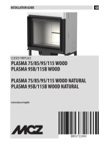
1.2 Fireplace identification
The fireplace is equipped with a metallic label containing the following information:
• CE marking.
• Manufacturer’s name and address.
• European homologation standards number.
• Appliance type.
• Fuel.
• Nominal heat output.
• CO (calculated at 13% of O2).
• Nominal electrical power.
• Rated frequency.
• Lot no.
• Minimum distance from combustible materials.
• Warnings.
The label is located on the upper part of the fireplace.
The label may be graphically different.
Via San Giuseppe, 2 - 24060 Telgate - BG - *
Tel. +39.035.8359211 - fax +39.035.8359200
Apparecchio funzionante a legna - Wood stove insert - Gerät geeinigt für Holzbetrieb - Inserts à
feu ouvert alimentés bois - Aplicaciones de fuego abierto alimentadas leña
Rendimento
Efficiency
Wirkungsgrad
Rendement
Rendimiento
Potenza elettrica nominale
Rated electrical power
Elektr. Leistungsaufnahme
Puissance électrique nominale
Potencia eléctrica nominal
Distanza minima materiali combustibili adiacenti
Min. clearance from combustible materials
Abstand zu angrenzenden entzündlichen Stoffen
Distance aux matériaux combustibles
Distancia a materiales combustibles adyacentes
Utilizzare solo combustibili raccomandati
Use recommended fuels only
Verwenden Sie nur die empfohlenen Brennstoffsort*
Utiliser seulement des combustibles recommandés
Utilizar sólo los combustibles recomendados
CO emissioni
CO emissions
CO emission
Emission de CO
Emisión de CO
Tensione/Frequenza nominale
Rated voltage/frequency
Spannung/Nennfrequenz
Tension/Fréquence nominale
Tensión/Frecuencia nominal
Temperatura media fumi
Medium flue gas temperature
Abgastemperatur Mittelwert
Température moyenne des fumées
Temperatura media de los humos
Leggere e seguire le istruzioni di funzionamento
Read and follow the operating instructions.
Lesen und befolgen Sie die Betriebsanleitungen
Lire et suivre les instructions de fonctionnement
Leer y seguir las instrucciones de funcionamiento
Potenza termica nominale
Rated heat output
Nenn-Heizleistung
Puissance nominale
Potencia térmica nominal
N° lotto
Legna-Wood-Holz-Bois- Leña
75/170 W
230 V
300
L144238
Cod UMEDB/C
292,7°C
14,7 kW
26
Potenza bruciata
Burned power
Max Heizleistung
Puiss. max. disponi*
Potencia quemada
Potenza termica resa all'ambiente
Space heating output
Heizleistung an den Raum
Puiss. émise dans la pièce
Potencia térmica al ambiente
Potenza ceduta al fluido
Power given to fluid
Heizleistung ans Fluid
Puissance cédée au fluide
Potencia cedida al fluido
2,8 kW
19,4 kW 12 kW
50 Hz
mm
0,46%
76%
Aria
10
CO
P
Qtot
Psh
Pw
ta
Matr: 031725
n° DOP JM 00020
the dop was drafted on the basis to the test report of accredited laboratory
the accreditation number of the laboratory is 0068 Istituto Masini
08
UNIVERSALJOLLY MEDIO
*Pursuant to European Regulation No. 305/2011, manufacturers are now required to have the DoP - Declaration
of Performance for each product of own design concerned; Jolly-Mec did namely provide all of these documents in
downloadable electronic form that you can easily see on the website of the Company at the following address: http://www.
jolly-mec.it.
ATTENZIONE

4
1.3 Technical data
4
Approval EN 13229
352 Burned power (by wood) Qtot 19,4 18,2 kW
365 Thermal rated output (by wood) P 14,7 13,9 kW
301 Consumption at max power Bt 4,5 4,2 Kg/h
356 Maximum output disposed of in the environment (by wood) Psh 2,8 4,2 kW
359 Power given to fluid (by wood) Pw 12 9,6 kW
052 Efficiency (by wood) η 76 76 %
455 Max. heated area depending the kind of house 65-90-150 70-100-180 m2
653 Smoke exhaust Ø 200 200 mm
451 Surface exchange 1,4 1,5 m2
652 Hot air outlet union Ø 100 100 mm
554 Air fan capacity 410 410 m3/h
253 Total weight 101 121 Kg
604 Installed electrical power 75/170 75/170 W
601 Nominal voltage/frequency 230/50 230/50 V/Hz
702 Min. draft 12 12 Pa
102 Max T smoke (by wood) 320 375 °C
105 Med T smoke (by wood) ta 292,7 283 °C
005 CO2 (wood) 8,7 7,1 %
002 CO (13% O2) (wood) 0,46 0,41 %
202 Smoke volume (by wood) m 12,9 14,92 g/s
701 Inflammable materials distance 300 300 mm
991 Maximum load (wood) 4 4,5 Kg
Code Description Version UM
Universaljolly Universaljolly
Medium Maxi
Recommended fuels: WOOD: dry beech, hornbeam, oak, locust (acacia) very dry
Primary air CLOSED
Damper CLOSED
Fan air delivery: 410 m3/h
Quantity, sizes and arrangement of wood: 4 Kg/h length 330 +/-30 mm arranged parallel to the front area
Power 12.7 kW
Procedures and adjustments for obtaining the above performance with model Maxi
The chart’s technical data was derived from certified data according to EN 13229 test methods.

5
1.4 Example of fireplace installed and clad
5
Ducting of air to upper floors
Ducting of hot air also to several
floors.
The powerful 410 m3/h
or 620 m3/h (optional) fan allows
hot air to be delivered to the
various rooms.
Base
Without masonry work, the ducting
can exploit the space freed in the
old flue for reaching the top floor
(using stainless steel pipes only).
Universaljolly inserted in an
existing structure
THE original appearance of
the room can be maintained by
fitting the Universaljolly insert
in the fireplace, which turns the
old fireplace into a real heating
system.
Closing
Finishing the insertion only
requires simple closing work.
Optimising flue draught
The old flue serves for holding
the new piping which is sized
to optimise the draught of the
new fireplace and to simplify
installation.
Ducting air to the various rooms
The air pipes can be concealed by
a covering in plasterboard.
Ducting outside the hood
By making a hole in the hood, the
air can be ducted to the various
rooms.
Insulation
The new fireplace must be
carefully insulated with rock wool
to prevent heat loss.
IMPORTANT!
Only use double-wall stainless steel pipes inside the hood and flue and for hot air ducting.

6
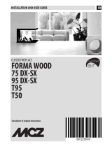
1.5 Fireplace parts
6
1
9
8
2
12
3
1
2
3
4
5
6
7
8
9
10
11
12
Exchanger
Support with grille for
inside suction (only for
do-it-yourself inside suction
model)
Ash pan
Cast iron grate
Fire bed with wood retainer
Ash pan support
Adjustable fume shutter
automatic opening pin
Fume outlet damper
Precut plugs (knock out only
for air ducting)
Fan
Electronic controller
Rock wool matting for boiler
insulation
610
7
5
4
11

7
1.6 Fireplace operation
7
1.6.1 Starting with wood
1.6.2 Electronic controller
The electronic controller is arranged for controlling the room air
fan, in order to set the optimum air flow level.
The ventilation level can be set manually by the user or
automatically.
In automatic setting (possible in the version with temperature
probe), the ventilation is set according to the fireplace
temperature.
A fan operation mode is provided, even with the fireplace off,
for room ventilation.
The user interface is in the wired version, already arranged for
the radiofrequency version.
Through the interface it is possible to set the various operation
modes and identify any faults.
Room temperature display (with remote control only).
Increase selected value
in manual programme
Decrease selected value
in manual programme
- Summer/Winter mode change
- Automatic fan speed display
DISPLAY
No communication with fireplace
(with remote control only)
The controller is arranged for
remote control link
norF
Operation programme
AU = Automatic
LX = manual with ventilation
level X (1-9)
OF = Off
RF reception in progress Winter mode (if the controller is not present
Summer mode is set)
Off/Manual/Automatic operation
Programme change
• Clean the fire bed and empty the ash pan
• On the display, choose winter through the correct button.
Press P and select the fan modality desired: Automatic or
Manual.
For detailed information on the Controller operation
,
see the SM/032 Card supplied.
• Fully open the grille on the ash pan.
• Prepare the wood and light the fire (it is advisable to use
firelighters or similar products)
• Close the door.
Fireplace heat output and load burn time are regulated by the
amount of combustion air; to adjust the amount, adjust the primary
air (opening or closing the ash pan grille).
To obtain a heating power of 23 Kw it is necessary to burn
5-6 kg of wood per hour.

8
1.6 Fireplace operation
8
1.6.3 Advice
Use only original spare parts recommended by the manufacturer.
Original spare parts are available through retailers, specialised
Tecnical Service Centers, or directly at the head office of Jolly
Mec Caminetti S.p.A.
Regular and methodical maintenance is all-important for correct
operation and maximum efficiency.
This is a high performing fireplace which works with a closed
door concept. If the doors are opened and the flue draught is
not optimal (12 Pa), small puffs of smoke may occasionally
occur.
If, for example, it is necessary to open the doors to load some
wood, check that you have opened the fume damper as far as
possible to prevent the formation of small puffs of smoke. When
you have finished and reclosed the doors, reset the damper to
its standard operating position.
WARNING!
In case of a power failure, if the fireplace is lit and
loaded with lots of wood, some electrical components
could become damaged.
In case of a power failure, check the heat output of the
fire and if high, remove a few pieces of wood to reduce
it.
ATTENZIONE!
The firebox must always be closed, except when
loading fuel, to prevent smoke escaping. For models
with two doors, always open (slowly) the right door
first and then the left one. The only part not covered by
cladding and therefore subject to high temperatures
is the glass.
THE fan must be activated with the fireplace lit, as the
”UNIVERSALJOLLY” is a very powerful heat exchanger fireplace.
Fig. 1
Damper in standard position (optimum fireplace efficiency)
Fig. 3
Damper shifted forward to further increase draught
MORE CLEANING = MORE EFFICIENCY
The fireplace can be used in summer to ventilate the rooms, by
setting the controller to SUMMER and adjusting the fan speed.
If the flue draught is insufficient and smoke escapes at the
doors, the draught can be adjusted by means of the damper
which can be positioned in order to facilitate the rear passage
of fumes. (
Fig. 2-3
).
If a decrease in draught is noticed, remove the damper
and clean any soot fallen from the flue onto the boiler.
If a decrease in hot air is noticed, this means that the fan needs
cleaning: access it by removing the fire bed; See par. 1.7.2
Fig. 2
Damper shifted forward to increase draught

9
9
1.7 Routine maintenance
1.7.1 Cleaning the fireplace
•
Cleaning the ash pan
Empty periodically when necessary.
•
Glass
Use products such as ”Fornet” or ones with similar characteristics.
Do not use aggressive cleaning products, which could damage
the paint on the trim around the glass. If the glass requires more
frequent cleaning, check the flue draught.
•
Cleaning the flue
Routine flue cleaning depends on the draught, fireplace use,
weather conditions and the type of wood or pellets used.
It is mandatory to clean the flue every year, by a specialised
technician, in autumn before lighting the fireplace.
1.7.2 Parts that can be removed to clean the fireplace or service the fan
NOTE!
The flue must be installed so that it can be easily brushed or
removed, and without any elbow bends or sections sloping in
the other direction.
Periodical annual flue cleaning will ensure optimum fireplace
draught and significantly reduces puffs of smoke when
opening the door to load wood.
1 2
3 4
5 6
1
2
3
4
5
6
Ash pan
Cast iron grate
Fire bed (remove only for
fan maintenance)
Rock wool insulation
(remove only for fan
maintenance)
Prebox (remove using a
Phillips screwdriver only for
fan maintenance)
Damper

10
1.8 Optionals
10
27
1
Exchanger guide support (only
for version with outside air
suction)
2
Outlet with adjustable closure for
hot air 180x120
3
Grille for outside air inlet
230x230 (only for version with
outside air suction)
4
Automatic closure box for
outside air inlet (only for version
with outside air suction)
5
Connection for connecting
automatic closure box to the fan
6
Smooth stainless steel flue Ø
200 length 500
7
Universal connection between
Ø200 mm exhaust pipe and flue
8
Double-wall flexible stainless
steel flue Ø 200
9
Smooth stainless steel flue Ø
200 (various lengths)
10
Connection for double-wall
flexible exhaust pipe Ø 200
11
Reduction adapter for exhaust
pipes, various sizes
12
45° bend for exhaust pipe in
stainless steel Ø 200
13
Connection for hot air ducting
Ø 80, Ø 100
14
Flexible aluminium pipe Ø 80 or
Ø 100 (various lengths)
15
T connection for aluminium
pipes Ø 80 or Ø 100 for hot air
ducting
16
Y connection for aluminium
pipes Ø 80 or Ø 100 for hot air
ducting
17
Straight connection for
aluminium pipes Ø 80 or Ø 100
for hot air ducting
18
Pipe clamps Ø 80, Ø 100, Ø
200
19
Rock wool matting for boiler
insulation
20
620 m3/h fan
21
Mesh for closing
22
Stainless steel meat grill with
removable handle 500x180
(400x180 for Medium model)
23
Cast-iron andirons with supports
24
Primary alloy non-stick plate
25
Stainless steel pizza shovel
26
Connection for fitting boiler hood
27
60 or 90 litre boiler hood
262524
23
22212019
171615 18
121110 13 14
8
765
3 421
9
All measurements are in millimetres (mm)

11
11
1.9 Installation and maintenance card use and keeping
•
Card recipients
The installation and maintenance card is intended for users responsible for fireplace operation; particular attention must be paid the parts
concerning safety.
•
Purpose of the card
The card contains information on correct use of the fireplace, according to the purposes for which it was designed and built.
It also provides information on weights, commissioning, repair and maintenance of the fireplace, in conformity with the limits set by the
manufacturer, inside the card.
•
Keeping the card
The installation and maintenance card is an integral part of the fireplace and must be kept until scrapping of the same.
It must be kept in a safe and dry place away from direct sunlight, and near the fireplace so that it is always readily available for reference.
Should the manual get damaged, the user must request a copy from the retailer where he purchased the appliance.
•
Updating the card
The installation and maintenance manual reflects the state of the art at the time the fireplace was marketed. The Manufacturer reserves
the right to make changes to the fireplace, and consequently to the relevant card, without having to update previous editions.
The user can always request information and updates which, when issued, become an integral part of the installation and maintenance
card.
If selling or transferring the fireplace, the user is requested to also give the new owner the card and in any case to inform the Manufacturer,
so that the new owner can receive subsequent supplements.
•
Cases relieving the Manufacturer from liability
The Manufacturer is relieved from any liability in the following cases:
a) improper use of the fireplace.
b) use not envisaged by specific national regulations.
c) incorrect installation.
d) feed faults.
e) failure to carry out maintenance as prescribed.
f) unauthorised modifications or operations.
g) the use of non-original replacement parts or not specific to the model.
h) total or partial non-compliance with the instructions.
i) exceptional events (e.g. breakage due to natural catastrophe).
j) damage caused by power failures, voltage rushes, electromagnetic fields.
k) the use of pellets with characteristics different from those recommended in this card.

12
12
1.10 Ecological regulations
1.10.1 DISCARDED MATERIALS AND THEIR DISPOSAL
Spare parts replaced during the machine’s product life are to be considered waste and must be taken to special col-
lection centres or entrusted to authorised disposal centres.
Ashes must be placed in a metal container with a sealed lid. Until the coals definitively go out, the closed container
must be placed on a non-combustible base and kept away from combustible materials.
Only when the ashes go out can they be thrown into the organic waste collection, naturally without nails or non-organic
materials.
The ashes from natural wood (untreated) derived from stove or fireplace combustion are mainly composed of calcium,
silicon, potassium and magnesium oxides.
The machine must be disposed of in a manner that complies with the laws in force and the environment.
PROTECT THE ENVIRONMENT !!!!
1.10.2 DISPOSAL OF THE MACHINE
The fireplace is mainly composed of ferrous materials, but it may also contain:
• piping
• insulating materials
• electrical parts etc.
• refractory materials
When you have finished using the fireplace definitively, do not dispose of it irresponsibly:
• empty the circuit completely (if present)
• remove piping (if present)
• remove plastic parts
• remove electric cables and electric components
These materials must be disposed of by specialised firms or according to the laws of the country where it is installed.
Furthermore:
• immobilise moving parts
• make the locks on the doors inoperative
Take the remaining part of the fireplace to the firms that dispose of ferrous materials.
NOTE: When taking it to the firms that dispose of ferrous materials, move the fireplace
according to the safety regulations in force.

13
13
2.1 Dimensions and weights
2.1.1 Universaljolly with outside suction
The fireplace is supplied on pallets, packed with a cellophane
hood and with the following parts:
• Complete boiler body
• Assembly card
• 410 m3/h fan (620 m3/h optional by request)
• Electronic controller
• Rock wool for boiler insulation
Width: Front 68 80 cm
Rear 46.5 53 cm
Height 50 58 cm
Depth 48 48 cm
Flue diameter 20 20 cm
Weight 80 100 kg
MEDIUM MAXI
2.1.2 Universaljolly do-it-yourself with inside suction
The fireplace is supplied on pallets, packed with a cellophane
hood and with the following parts:
• Complete boiler body
• Assembly card
• 410 m3/h fan (620 m3/h optional by request)
• Electronic controller
• Rock wool for boiler insulation
• Support with grille for inside suction
Width: Front 68 80 cm
Rear 46.5 53 cm
Height 55 63 cm
Depth 48 48 cm
Flue diameter 20 20 cm
Weight 85 105 kg
MEDIUM MAXI

14
14
2.2 Flue
The flue is an all-important element for
fireplace’s proper
functioning and must comply with the standards:
EN1856-1 -Fireplaces: requirements for metal fireplaces-
Part 1:Products for fireplace systems.
EN1856-2 -Fireplaces: requirements for metal fireplaces-
Part 2: Internal ducts and metal exhaust pipes
EN10683 -Installation requirements
The cross section of the flue must be that indicated in the
fireplace technical characteristics. Each stove must have its
own flue, which must not be shared by any other emissions
(fireplaces, boilers, stoves, etc.)
The dimensions of the flue depend on its height, to be measured
from the fireplace to the bottom of the chimney cap.
To ensure adequate draught, the fume outlet area of the cap
must be double the cross section area of the flue. The pipe
used to exhaust the fumes generated by the natural-draught
fireplace must:
- be fumetight, impermeable and adequately insulated
according the conditions of use (see UNI 9615).
- be made from materials able to withstand the normal
mechanical stresses, heat, and be resistant to the action of
fumes and possible condensate.
- be mainly vertical, with deviations from the axis not exceeding
45°.
- be installed at a suitable distance from combustible or
flammable materials, by an air gap or suitable insulation
- preferably have a round internal section: square or rectangular
sections must have rounded corners with radius of at least 20
mm.
- have a uniform, free and independent internal section.
-
have the rectangular sections with a max. ratio between the
sides of 1.5:1.
An antiwind-type cap is advisable. If the flue is installed
externally, it must be insulated to prevent the cooling of fumes
and the formation of condensate. The same applies to the
section from the roof to the chimney cap.
For the connection between the fireplace and flue, or in the
presence of branches or bends, or for easier, quick and safe
installation, it is advisable to use double-wall stainless steel
pipes without insulation inside hoods. Non-combustible materials
resistant to the fumes and their possible condensate must be
used for installing the fume ducts.
The use of asbestos cement pipes to connect appliances to the
flue is prohibited.
The fume ducts must not cross rooms in which the installation
of combustion appliances is prohibited. The fume ducts must
be installed in such a way as to ensure fume tightness when
the fireplace is in negative pressure operating conditions and
to avoid the formation of condensate and its conveyance to
the unit.
Horizontal sections should be avoided as much as possible.
For exhaust pipes which must reach ceiling or wall outlets
that are not coaxial with respect to the fireplace fume outlet,
changes of direction must be made using open elbows not
exceeding 45° (see
Fig. 1
).
Do not use elements sloping in the other direction. The flue must
be designed allow removal of soot and brush cleaning. The
exhaust pipe must have a uniform cross section. Any changes
in section are only permitted at the generator outlet; reduction
adapters must not be used at the connection with the flue.
Do not route other air supply and system pipes inside the
exhaust pipes even if the latter are oversized.
Do not support the weight of the flue on the stove/fireplace
connection. Use special brackets or separate supports.
Other stoves, fireplaces, boilers or air extractors must not
be installed in the same room (excluded of the type “C”
according to UNI 10683).
Minimum height of exhaust pipe: 3 metres.
Fig. 1

15
15
2.3 Assembly steps
Fig. 1
•
Forced air version with outside suction
•
Do-it-yourself version with inside suction
PLAN VIEW OF EXISTING FIREPLACE dimensions in cm
20x20 outside air inlet
46
35
20 (Profondità)
40
2
Rock wool
Existing fireplace walls
Smoothing
with cement
Power cable
entry
Optional guide support (if
provided for) or exchanger
Fan
compartment
35x40x20h
46
35
20 (Profondità)
40
2
Rock wool
Existing fireplace walls
Smoothing
with cement
Power cable
entry
Support with grille for inside
suction
Fan
compartment
35x40x20h
1.
Make the air inlet communicating with the outside of dimensions
20x20 cm. or with a Ø 200 mm aluminium pipe (
Fig.1
).
2.
Create the fan compartment according to the dimensions given
in the drawings (
Fig.1
and
Fig.2
).
3.
Make a hole for power cable entry (
Fig.1
).
4.
Smooth everything with normal mortar.
5.
If use of the support with grille
(optional) is provided for, place it
level in the right position and fix
it with mortar and plaster, filling
from the outside.
For DO-IT-YOURSELF model,
place the support with grille for
inside suction level in the right
position and fix it with mortar and
plaster, filling from the outside.
6.
Fix the exchanger with silicone,
applying a layer before inserting, in order to prevent air
passages between the exchanger and fireplace.
7.
If air ducting (with relevant optionals) to other rooms is provided
for, prepare the holes in the hood or rear wall or where most
convenient for the pipes (
Fig. 9
and
Fig. 12
). If the flue is large
enough for routing the air ducting or fume exhaust it can be
used for that purpose after ducting the fireplace fume exhaust
with a double-wall stainless steel pipe up to the chimney cap
(
Fig. 13
).
8.
Apply the universal connection (
Fig. 5
RECOMMENDED
Optional) or insert a section of double-wall stainless pipe the
same diameter as the exchanger (Ø 200) in the fireplace flue,
starting from the exchanger and entering the flue by at least 50
cm (
Fig. 4
).
9.
Place mineral wool between the existing flue and the stainless
steel pipe in order to prevent smoke returning and soot falling,
thus eliminating the risk of fire (
Fig. 3
) or, if possible, make a
hole in the hood and seal (from above) with mortar or plaster.
10. Spread the rock wool matting (supplied) on the walls of the
fireplace (
Fig. 4
).
•
For the assembly steps, follow the numbers
Fig. 2 Fig. 3 Fig. 4

16
16
2.3 Assembly steps
Fig. 7 Fig. 8
Connecting the flue with universal
connection (optional)
Apply the universal connection at a
height within hand’s reach for filling
(with cement and plaster) with funnel
shape (
Fig. 5
).
Insert the piece of double-wall flexible
stainless steel pipe of length equal to
the distance between the exchanger
and the outside of the connection
(
Fig. 6
).
RECOMMENDED
Flue
Mixture with
plaster and cement
(smoothen by
hand)
Universal connection
(optional)
Possible top access
by making a hole
in the flue for filling
inside the hood
Stainless steel pipe
Fig. 5 Fig. 6
Fig. 10Fig. 9

17
2.3 Assembly steps
Fig. 11
Fig. 15
Fig. 16
Fig. 13
11. Remove the galvanised protection plate on the fan support
(bottom of fireplace exchanger).
12. If ducting is provided for, using a hammer knock out the
precut sheets on the top hot air outlets (
Fig. 11
) and insert
the special connections to test before inserting the boiler
(optional). The air connections can also be applied with the
fireplace fitted, by removing the dampers.
13. Place the exchanger in the right position and make sure
the fan does not suck air between the exchanger and the
fireplace base.
14. For the hot air ducting, connect the air pipes by means of the
fume exhaust.
15.Insert the air ducting pipes on the special connection
(optional) and fix them with the pipe clamp (optional).
16.
Insert the connection and pipe in the support and turn to
secure the connection (
Fig. 12
). N.B. It is advisable to try
fitting the connections before inserting the fireplace.
17. Insulate the top part of the exchanger.
18. Lower the stainless steel pipe all the way into the special
support on the exchanger, operating from the fume exhaust
or, if possible, from the outside, forcing it down with hands
or using a curved iron (
Fig. 8
) to hermetically close the fume
passage.
19. Position the controller, securing it to the fireplace structure
at the front or the side (
Fig. 14
and
Fig. 15
).
20. Bend the bottom edge of the fan down to prevent vibration
and noise (
Fig. 16
), insert it in the space and secure with the
special screws.
21. Fit the prebox and secure it with self-tapping screws.
22. Plug any space at the front between the exchanger and the
fireplace with the mesh, securing it with self-tapping screws
or other material suitable for the fireplace, mortar, bricks,
marble, etc. (
Fig. 13
).
17
Fig. 12 Fig. 14

18
18
2.4 Electrical connections
IMPORTANT!
The electrical connections between the various components must be made in conformity with the safety regulations.
•
Replacing the thermostat
1. Remove the fire bed.
2. Unscrew the thermostat protection cap
3. Unscrew the thermostat and replace it.
Thermostat
Probe PT100
Control display
Fan
230V Line
Earth
Connect to
the earth
of the
metal box
Manual
version
Automatic
version
Electrical connections must be carried out by skilled personnel according to the regulations in force ( 2014/30/UE and 2014/35/UE)
The representation of the components is approximate, but they can change in terms of shape
/