
AMX-1842 HD/SD 4 AES Embedder
Guide to Installation and Operation
M684-9600-102
November 2011
AMX-1842 Page 1 of 10
AMX-184 2
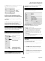
Description
The AMX-1842 is a high-quality embedder which embeds
up to four AES 24-bit 48 kHz digital audio signals into a
single HD/SD serial digital video signal. It includes audio
and video signal presence detection and reporting, and
local or remote configuration and control. A unique feature
is its ability to embed time code, a serial RS-422 data signal
and two GPI status signals into the video signal. The card
has built-in audio tone, time code and video color bar test
signals.
The AMX-1842 is designed for use in the DENSITÉ frame,
with the appropriate double-width rear panel.
Video - Features
• Serial HD/SD-SDI input with automatic equalization for
up to 110/250 meters of cable.
• Automatic detection of video input format
• Automatic detection of input video loss and switchover
to local black for continuity of embedded audio.
Audio - Features
• AES inputs: either 110 Ω balanced or 75 Ω
unbalanced, depending on rear panel in use
• Sample rate conversion for asynchronous AES inputs
• Audio input channel gain selectable from -96dB to
+12dB by 0.5dB steps
• Audio groups insertion/pass-through/delete
• Selectable audio delay of up to 3 frames in ½ frame
steps
• Left/Right channels swappable for each AES input
• Automatic mute on AES error
• Selectable routing of AES signals to audio groups
• Dolby-E compatible (48kHz synchronous)
• Cards cascadeable to embed 4 groups (16 channels)
• 24-bit digital audio embedding
• Monitor selector for Densité frame monitor switcher
(MSB)
• Universal reference signal output for audio DAC
Embedding Other Signals - Features
• Linear Time Code (LTC) embedding
• RS-422 serial data input for embedding as ANC data.
• Sampling of two GPI inputs for embedding as ANC
data.
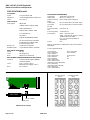
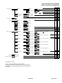
FUNCTIONAL BLOCK DIAGRAM
SPECIFICATIONS
VIDEO INPUT
Video Signal:
HD/SD-SDI
SMPTE 292M / SMPTE 259M
(see list of supported formats below)
Cable Length:
up to 110/250 meters of Belden 1694A
Return Loss:
>15 dB, 5 MHz to 1.485 GHz
AUDIO AES-3id INPUT
Signal:
AES-3id (SMPTE 276M)
Level:
0.2 to 2.0 Vp-p
Impedance:
75 Ω unbalanced
Cable length:
>400 m
AUDIO AES3 INPUT
Signal:
AES3
Level:
0.2 to 7.0 Vp-p
Impedance:
110
Ω
balanced
Cable length
>200 m
AUDIO AES SIGNALS
Sampling Rate:
48kHz synchronous or asynchronous
Dolby-E Rate:
48kHz synchronous
Bits:
24-bit

AMX-1842 HD/SD 4 AES Embedder
Guide to Installation and Operation
Page 2 of 10 AMX-1842
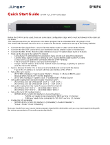
AMX-1842 Front card edge
AMX-1842 Rear Connector Panels
Select
Status
Status LED
SELECT button
AMX-1842
SPECIFICATIONS(cont’d)
LTC SIGNAL
Signal:
LTC per SMPTE 12M
Impedance:
< 10kΩ (bridging 600Ω) unbalanced
Level:
0.2 to 5Vp-p
VIDEO OUTPUT
Video Signal:
HD/SD-SDI
(SMPTE 292M / SMPTE 259M)
Audio embedded per
SMPTE 299M / SMPTE 272M
LTC embedded as
ATC/DVITC
(SMPTE RP188/SMPTE 266M)
RS-422 and two GPIs embedded
as ANC data per SMPTE 291M
(Proprietary type 1 DID)
Return Loss:
>15 dB up to 1.485 GHz
Wideband Jitter:
as per SMPTE-259M-C and 292M
ANC SERIAL DATA INPUT
Signal:
RS-422
Level:
200 mVpp (min)
Rate:
38.400 or 115.200 bauds
ANC GENERAL PURPOSE INTERFACE (GPI) OUTPUT
Signal (2):
Contact closure (opto-isolated),
common ground
Level:
True = 0 to 0.8 V (max.)
Maximum input voltage = ±5.5 V
Rate:
DC to 250 Hz
PROCESSING PERFORMANCE
Signal Path:
10-bit video / 24-bit audio
Video Delay:
HD: 4.5 µs / SD: 11.5 µs
Audio Processing
Delay:
875 µs audio insertion delay ‡‡
Audio Delay:
Up to 3 video frames (1/2 frame steps)
LTC Delay:
Up to 3 video frames (one frame steps)
RS-422
Processing delay:
max 500
µ
s ‡‡
GPI
Processing delay:
4 video lines ‡‡
Test Signals:
Video - color bars 100%
Audio - 1 kHz tone (R steady, L pulsed)
-18dBFS (EBU R49, R68)
LTC – 10 second loop starting at
23:59:00:00
Power:
6 W
Note ‡‡: Applicable to combinations of this card and ADX-
1842/1852.
List of supported formats:
HD-SDI formats :
1920 x 1080/59.94/I
1920 x 1080/50/I
1920 x 1080/29.97/P
1920 x 1080/25/P
1920 x 1080/24/P
1920 x 1080/23.98/P
1920 x 1080/29.97/PsF
(detected as 1920 x 1080/59.94/I)
1920 x 1080/25/PsF
(detected as 1920 x 1080/50/I)
1920 x 1080/24/PsF
1920 x 1080/23.98/PsF
1280 x 720/59.94/P
1280 x 720/50/P
SD-SDI formats :
525
625
AMX-1842-75-DRP
AES-3id
AMX-1842-110-DRP
AES3

AMX-1842 HD/SD 4 AES Embedder
Guide to Installation and Operation
AMX-1842 Page 3 of 10
INSTALLATION
Make sure the following items have been shipped with your
AMX-1842. If any of the following items are missing,
contact your distributor or Miranda Technologies Inc.
* AMX-1842 Digital Audio Embedder
* AMX-1842 rear panel (see figure for options)
The AMX-1842 and its associated rear connector panel
must be mounted in a DENSITÉ frame. It is not necessary
to switch off the frame’s power when installing or removing
the AMX-1842. See the DENSITÉ Frame manual for
detailed instructions for installing cards and their
associated rear panels.
The AMX-1842 has multiple audio and video inputs and
outputs, and making space for all the necessary
connectors at the rear of the frame requires a double-width
rear panel.
When a double–width rear panel has been installed, the
AMX-1842 must be installed in the right-most of the two
slots covered by the panel in order to mate with the panel’s
connectors. If it is placed in the wrong slot, the front panel
LED will flash red. Move the card to other slot for correct
operation. No damage will result to the card should this
occur.
OPERATION
Overview
The DENSITÉ frame incorporates a central controller card,
located in the center of the frame, which is equipped with
an LCD display and a control panel. The controller handles
error reporting and local and remote control for all cards
installed in the frame. The display and control panel are
assigned to the card in the frame whose SELECT button
has been pushed.
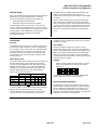
Status Monitor LED
The status monitor LED is located on the front card-edge of
the AMX-1842 module, and is visible through the front
access door of the DENSITÉ frame. This multi-color LED
indicates module status by color, and by flashing/steady
illumination, according to the following chart (which also
indicates fault reporting for this card on the DENSITÉ
frame’s serial and GPI interfaces).
REPORT
COLOR (F=flashing)
SERIAL
GPI
G
Y
R
FR
No errors
No signal
No rear
Test mode
: Factory default. User configurable
A “Flashing Yellow” Status LED indicates that the SELECT
button on the front panel has been pushed, and the
controller display and control panel are now assigned to
this card. The LED color assignments for some error
conditions can be reconfigured by the user (see the chart
and menu for details).
User Interface
Pushing the SELECT button will cause the on-card
STATUS LED to flash yellow, and the card identification
and the current status will be shown on the controller card’s
display. The STATUS LED will revert to it’s normal state
upon a second push of the button, or after a short delay.
The messages which may appear are shown in the top line
of the menu chart on page 3
Example :
SELECT button pushed twice when there is no input
signal connected to the rear panel and the LED is
steady red:
Use the local control panel to access the detailed status
report shown in the STATUS menu on page 3.
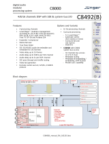
Operating Parameter Adjustment
The AMX-1842 has operating parameters which may be
adjusted at the controller card interface. After pressing the
SELECT button on the AMX-1842 card, use the keys on
the local control panel (described in the Controller card
manual) to step through the displayed menu and adjust the
parameters. The menus are shown below.
A M X - 1 8 4 2
A LN O S I G N

AMX-1842 HD/SD 4 AES Embedder
Guide to Installation and Operation
Page 4 of 10 AMX-1842
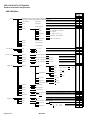
AMX-1842 Menu
HD SD
[ 10,…, 14
, …, 20]
in 525
[ 7, …, 16
, …, 22 ]
in 625
[ AES IN 1-2, AES IN 3-4, PASS
, DELETE ]
[ AES IN 1-2, AES IN 3-4, PASS
, DELETE ]
[ AES IN 1-2, AES IN 3-4, PASS
, DELETE ]
[ AES IN 1-2, AES IN 3-4, PASS
, DELETE ]
[ 1
, 2, 3, 4, 5 ]
[ 1
, 2, 3, 4, 5 ]
CONSUMER / PROFESSIONAL
LINEAR PCM / NON PCM
Same as AES IN 1
Same as AES IN 1
ENCODING
Same as AES IN 1
USE
x
x
x
x
x
x
x
x
x
x
x
x
x
x
x
x
x
x
x
x
x
16 BIT / 20 BIT / 24 BIT / OTHER
NONE/ PRESENT
USER PRESET**
Resolution
affected by
input
x
x
x
x
x
x
INPUT SOURCE**
AUDIO GROUPS
AES IN 1
AES IN
LTC IN
AES IN 2
STATUS
1080p23.98sF/ 1080p25/ 1080i50/ 1080p29.97/ 1080i59.94/ 625/ 525
N.I. / 2 CHANNEL / 1 CHANNEL /
P/S / STEREO
N.I. / NONE / 50 / 15-us / J.17
MODE
EMPHASIS
NO REAR/ NO SIGNAL/ 720p50/ 720p60/ 720p59.94/ 1080p24/ 1080p24sF/
NONE/ 1234
NONE/ 1234
BITS
AES IN 3
AES IN 4
LOAD
GROUP 2
SAVE
GROUP 1
DVITC
DUPLICATE
AES IN 3
DELAY
DELAY
GROUP 4
GROUP 3
CONFIG AES**
SAMPLE RATE CONV
CONFIG LTC**
[ NO
, YES ]
EMBED
Same as AES IN 1
PHASE INVERT
AES IN 2
AES IN 4
AES IN 1
Same as AES IN 1
EMBED BITS
LINE SELECT
[ 20 BIT, 24 BIT
]
[ NONE
, 0.5 FRAME, 1.0 FRAME, 1.5 FRAME, 2.0 FRAME, 2.5 FRAME, 3.0 FRAME ]
[ OFF
, ON ]
[ OFF
, ON ]
[ OFF
, ON ]
Same as AES IN 1
MUTE L&R
SWAP L&R
[ OFF
, AUTO ]
LEVEL
[ NONE
, 1 FRAME, 2 FRAME, 3 FRAME ]
[ OFF
, ON ]
LEFT
RIGHT
LOCK
[MUTE, -95.5 dB, ..., 0 dB
, ..., 12dB]
[MUTE, -95.5 dB, ..., 0 dB
, ..., 12dB]
[ OFF, ON
]
[ OFF
, ON ]
LEFT
RIGHT

AMX-1842 HD/SD 4 AES Embedder
Guide to Installation and Operation
AMX-1842 Page 5 of 10
[] Parameter to select
** Press Select pushbutton to activate selection.
Underlined values in the parameter value lists are the factory
default values, and will be applied when factory default-restore
is selected.
[RESTORE]
[ GREEN
, YELLOW, RED, FLASH RED ]
[ GREEN
, YELLOW, RED, FLASH RED ]
[ GREEN
, YELLOW, RED, FLASH RED ]
[ OFF
, ON ]
[ OFF
, ON ]
[ GREEN, YELLOW, RED
, FLASH RED ]
[ GREEN
, YELLOW, RED, FLASH RED ]
ALARM LEVEL
[ NONE
, GPI ]
x
x
x
[ NONE, ODD
, EVEN ]
x
x
x
x
x
x
x
x
x
x
x
x
x
x
x
x
x
x
x
x
x
[ PASS
, OVERWRITE ]
[ PASS
, OVERWRITE ]
TC LOOP
ANC SIGNALS**
RS-422
SAMPLED GPI 1
[ OFF
, ON ]
SAMPLED GPI 2
COLOR BAR
[ OFF
, TONE ]
TEST**
AES IN 1
AUTO BLACK**
[ OFF
, TONE ]
[ OFF
, TONE ]
[ OFF
, TONE ]
EMBED
ALARM LEVEL
ALARM REPORT
NO AES3
ALARM LEVEL
ALARM REPORT
ALARM REPORT
ALARM LEVEL
ALARM REPORT
FACTORY DEFAULT**
AES IN 2
AES IN 3
AES IN 4
NO SIGNAL
NO AES1
NO AES2
TEST MODE
CONFIG ALARM**
AMX-1842:XXX
x
x
VERSION
PARITY
BAUD RATE
NO LTC IN
x
NO AES4
x
x
[ NONE
, GPI ]
[ NONE
, GPI ]
[ NONE
, GPI ]
[ GREEN
, YELLOW, RED, FLASH RED ]
[ NONE
, GPI ]
[ NONE
, GPI ]
[ GREEN
, YELLOW, RED, FLASH RED ]
[ NO
, YES ]
ALARM REPORT
ALARM REPORT
[ 38.4 Kb
, 115 Kb]
ALARM LEVEL
ALARM REPORT
[ NONE
, GPI ]
ALARM LEVEL
ALARM LEVEL

AMX-1842 HD/SD 4 AES Embedder
Guide to Installation and Operation
Page 6 of 10 AMX-1842
USER PRESET menu
LOAD: Selects which predefined parameter settings will be
used by loading a personalized profile.
SAVE: Saves the parameter settings in one of the five
possible user preset profiles.
INPUT SOURCE menu
GROUP1, GROUP2, GROUP3, GROUP4: Selects the
source of audio for the four embedded audio groups. AES
IN 1-2 and AES IN 3-4 select audio from the AMX-1842
inputs. PASS leaves the incoming embedded audio group
intact, passing it through to the HD/SD-SDI output. DEL
deletes the incoming embedded audio groups, leaving the
HD/SD-SDI output without embedded audio. Sample rate
converters permit the AES inputs to be synchronous or
asynchronous.
Note: The standard for embedded audio specifies 48kHz
sampling, synchronous to video. Sample rate converters
permit the input of asynchronous linear PCM audio;
however, AES signals containing non-PCM audio must be
synchronous 48kHz. Asynchronous inputs will affect the
integrity of channel status and user data, causing error
flags to be set that may be detected by downstream
equipment.
CONFIG AES menu
AES IN 1, 2, 3, 4: Select MUTE: ON or OFF, SWAP L&R:
ON or OFF, or SAMPLE RATE CONV: OFF or AUTO for
each of the four AES channels. In AUTO mode, AES input
detected as non-PCM audio will automatically turn off the
sample rate conversion process.
LEVEL: Sets the audio gain from -96 dB to +12 dB in 0.5
dB steps.
PHASE INVERT: When “on”, inverts the selected audio
channel phase.
DELAY: sets the delay of the AES signal as it passes
through the embedder, from NONE to 3 video frames by
0.5 frame steps.
EMBED BITS: Select the number of embedded bits in the
AES signal to either 20 or 24 bits.
CONFIG LTC menu
EMBED: Permits the user to embed LTC, as ATC into an
HD-SDI signal or as DVITC into a SD-SDI signal.
DELAY: LTC delay selectable between NONE and a
number of video frames (1 to 3).
DVITC (only in video SD mode) : LINE SELECT allows
user to choose the position of DVITC in the video signal.
DUPLICATE fonction allows the user to insert DVITC twice,
on two different video lines.To insert DVITC twice, set
DUPLICATE feature to ON.
ANC SIGNALS menu
RS-422: The incoming RS-422 serial data may be
embedded as ANC data. Select PASS to leave any
already embedded RS-422 data untouched (no insertion)
or OVERWRITE, which embeds incoming RS-422 data to
the HD/SD-SDI signal while any existing embedded RS-
422 data is removed. Only works with signals at 38.400 or
115.200 Bauds with accurate selection of BAUD RATE.
SAMPLED GPI 1, 2: The incoming GPI status data is
sampled and may be embedded as ANC data. Select
PASS to leave any already embedded GPI data untouched
(no insertion) or OVERWRITE, which embeds incoming
GPI data to the HD/SD-SDI signal while any existing
embedded GPI data is removed.
AUTO BLACK menu
Turn AUTO BLACK ON or OFF. Auto Black replaces the
video input with a locally-generated video black in the
event of an input failure, to maintain audio embedding.
CONFIG TEST menu
AES IN 1, 2, 3, 4: User can enable (TONE) or disable
(OFF) a test tone (1 KHz, R-steady, L-pulsed, at –18dBFS)
on each of the four AES channels individually.
COLOR BAR: User can enable (ON) or disable (OFF) color
bars on the video output.
TC LOOP: User can enable a test loop (10 second loop
starting at 23:59:00:00) that is inserted into the video as
ATC (HD-SDI video) or DVITC (SD-SDI video).
CONFIG ALARM menu
The user can configure the status LED presentation
(ALARM LEVEL) and fault reporting (NONE or GPI) for
some of the fault conditions of the AMX-1842. Those not
listed here are factory-set and cannot be user-modified.
NO SIGNAL: Errors include no signal attached to the card
input, or faulty incoming HD/SD-SDI signal.
TEST MODE: Indicates whether test signals are present
on any of the AMX-1842 outputs (audio or video).
FACTORY DEFAULT menu
Select RESTORE to reset all of the menu-adjustable
parameters to a factory-preset state (indicated in the menu
by an underline in the list of available choices).

AMX-1842 HD/SD 4 AES Embedder
Guide to Installation and Operation
AMX-1842 Page 7 of 10
iControl Interface
The AMX-1842 can be operated using Miranda’s iControl
system. This manual describes and explains the control
panel associated with the AMX-1842. Please consult the
iControl User’s Guide for information about setting up and
operating iControl.
In Control Navigator or iControl Websites, double-click on
the AMX-1842 icon to open the control panel.
There are 8 sections in the AMX-1842 iControl panel:
Status Bar: located at the top of the panel, it provides
status icons for several key items and text messages
explaining the detected errors. A complete description of
the Status bar begins on this page.
Select the following tabs by clicking on their name at the
left side of the panel:
Audio: provides controls for processing and embedding
audio signals. A complete description of the Audio tab
begins on this page.
Metadata : gives access to the controls for LTC, RS-422
and GPI status data embedding in an HD/SD SDI signal. A
complete description of the Metadata tab begins on page
8.
Input Error: allows the user to turn on and off the auto
black feature. A complete description of the Input error tab
begins on page 9.
Test: gives the option to insert test signals. A complete
description of the Test tab begins on page 9.
Factory: Allows the user to reset the options to the default
factory-preset settings. A complete descrition of the
Factory tab begins on page 9.
Info: shows information about the AMX-1842 and allows
entry of some data. A complete description of the Info tab
begins on page 9.
User Presets: Allows the creation of user profies for a
personalised configuration of the AMX-1842. A complete
description of the User presets begins on page 9
Status bar
The status bar provides a continuous update of the status
of the AMX-1842. The status bar includes three sections:
Header
Icons
Message area
The header gives the product’s name, and identifies the
slot in which it is installed in its Densité frame. At the left is
a status icon whose color shows the overall status of the
AMX-1842:
Green = OK
Yellow = warning
Red = error
The 3 icons monitor specific aspects of the AMX-1842’s
operations. Move the cursor over an icon to see its current
status in the message area below the icons. If there is an
error status, the message will appear automatically
The first icon shows whether the remote control of this
AMX-1842 device is enabled or not.
The second icon shows the input status. Move the cursor
over the icon to display the audio format.
The third icon indicates if audio or video test signals are
active.
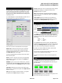
Audio
The audio tab shows the audio groups detected and
provides resources for managing the audio processing of
the AMX-1842.
Group detected: indicates embedded audio groups in the
AMX-1842 SDI imput by turning green.

AMX-1842 HD/SD 4 AES Embedder
Guide to Installation and Operation
Page 8 of 10 AMX-1842
AES detected: indicates AES audio on the indicated AMX-
1842 AES input by turning green.
To configure the AES digital audio signals, access the
AES1 to 4 tabs. There are two sliders (left and right for
stereo sound) available to set the level from -96 dB to +12
dB in steps of 0.5 dB. To invert the selected audio channel
phase, check the phase invert boxes. The lock option
locks both channel level sliders together, so that moving
one slider moves the other one as well. The mute option
mutes both audio channels completely. The swap option
interchanges the right and the left audio channels. The
sample rate converter can be set to either auto or off.
While in auto mode, the sample rate conversion process is
automatically turned off upon detection of non-pcm channel
status.
The Delay tab allows the user to set the delay of the AES
audio as it passes through the embedder. The delay is
selectable between none, and a number of video frames (0
to 3 frames in 0.5 frames steps).
The Embedding tab specifies the content of the AES
groups embedded in the output signal. Each group can be
composed of a pair of AES inputs (AES1-2 or AES3-4). If
the video input already contains an embedded audio group,
it can either be allowed to pass through directly without
modifications (PASS) or it can be deleted (DELETE). The
SD Embed bits is not selectable for HD (24 bits). For SD
signals, the options are 20 or 24 bits
The status tab monitors some of the information carried in
the AES inputs channel status..
The Bits status monitors the audio samples word length (in
bits). The possible values are 16 bits, 20 bits, 24 bits or
other. If the information is not available, it will show as N/I.
The Mode status monitors the channel mode. The possible
values are two channels (Two ch), one channel (One ch),
primary or secondary (Pri/Sec), Stereo or Other. If not
indicated, it will show as N/I.
The Emph status monitors the audio channel emphasis.
The possible values are none, 50/15 µs (CD type) and
J.17. If not indicated, it will show as N/I.
The Use status monitors the use of channel status block.
The possible values are either professional (PRO) or
consumer (CONS).
The Encd status monitors the audio channel encoding
type. The possible values are PCM or NPCM (non PCM).
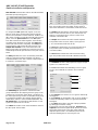
Metadata
The Metadata tab offers setting options for 3 types of input
signals: LTC, RS422 and GPI.
The LTC window allows the embedding of an LTC signal,
as ATC, into an HD-SDI or as DVITC into an SD-SDI
signal.
A: the presence icon shows if an LTC signal is detected by
turning green.
B: the insertion can be toggled to OFF or ON, to disable or
activate the embedding of the LTC signal into the HD/SD
SDI dignal.
C: the delay option allows correction of lipsync problems
by adding up to 3 frames of delay.
D: the DVITC menu has two parameters, Insert line and
duplicate. The insert line option allows the user to choose
the position of the DVITC in the video signal, while the
duplicate option inserts a second DVITC packet on the
video line following the one chosen by the user.
A
B
C
D

AMX-1842 HD/SD 4 AES Embedder
Guide to Installation and Operation
AMX-1842 Page 9 of 10
The RS-422 tab allows the embedding of an RS-422 serial
data as ANC data in the HS/SD SDI signal.
Setting the insertion option to OFF will leave any already-
embedded RS-422 data untouched, while setting it at ON
will remove any existing embedded RS-422 data and
embed the incoming RS-422 data in the HD/SD SDI signal.
The parity pulldown, allows the user to set the parity to
NONE, ODD or EVEN, insuring the continuity of the input
signal’s parity.
The GPI insertion tab allows the embedding of sampled
GPI status data as ANC data. Setting the option OFF will
not insert the GPI data, leaving the already embedded data
untouched, while setting it to ON wil overwrite it,
embedding the new GPI data in the HD/SD-SDI signal.
Input error
In the event of an imput failure, activating the auto black
feature will replace the video input with a locally generated
video black in order to maintain audio embedding.
Test
The test menu allows the user to enable test signals on the
AES and video outputs for troubleshooting purposes.
Factory
Clicking the Load Factory button will restore all of the
adjustable parameters to a factory-preset state. Those
preset settings are indicated by an underline in the AMX-
1842 menu on pages 4 and 5 of this manual.
Info
The Info tab provides information about the AMX-1842,
and provides some data entry options.
Label and Short label: type a label and a short label for
this device in the appropriate data entry boxes.
Source ID: enter the source ID
The details option gives additional information about the
device. The manufacturing process, firmware version,
service version and panel version can be found there.
The advanced tab shows the long ID of the device. The
Miranda Long ID is the address of this AMX-1842 in the
iControl network.
Open the remote system administration tab to acess the
“joining locators: AMX-1842” window.
User presets
User Presets
The AMX-1842 has memory registers which can hold up to
5 user-defined parameter settings.
Select any one of the five presets using the pull-down list.
The name of the currently-selected User Preset is shown
on the name bar.
• Click Load to load the contents of the selected User
Preset into the AMX-1842. All parameter settings and
values will be replaced by the contents of the selected
User Preset.
• Click Save to store the current parameter settings and
values from the AMX-1842 into the selected User
Preset. The existing contents of the preset will be
overwritten.
Enables color bars into the
video output.
Enables a test tone (1 KHz,
R-steady, L-pulsed, at-18
dBFS) in each of the four AES
channels individually
Enables an output test loop
(10 second loop starting at
23:59:00:00) in the video as
ATC into HD-SDI or as DVITC
in SD-SDI video.
Only supports
38,4 Kb
and 115 Kb

AMX-1842 HD/SD 4 AES Embedder
Guide to Installation and Operation
Page 10 of 10 AMX-1842
Electromagnetic Compatibility
This equipment has been tested for verification of compliance with FCC Part 15, Subpart B requirements for Class A
digital devices.
NOTE: This equipment has been tested and found to comply with the limits for a Class A digital device,
pursuant to part 15 of the FCC Rules. These limits are designed to provide reasonable protection against
harmful interference when the equipment is operated in a commercial environment. This equipment generates,
uses, and can radiate radio frequency energy and, if not installed and used in accordance with the instruction
manual, may cause harmful interference to radio communications. Operation of this equipment in a residential
area is likely to cause harmful interference in which case the user will be required to correct the interference at
his own expense.
This equipment has been tested and found to comply with the requirements of the EMC directive 2004/108/CE:
• 2004/108/EC Electromagnetic Compatibility (EMC) Directive
• EN 55022 Conducted emissions, Class A
• EN 55022 Radiated emissions, Class A
• EN 61000-3-2 Harmonic current emission limits
• EN 61000-3-3 Voltage fluctuation and flicker limitations
• EN 61000-4-2 Electrostatic discharge immunity
• EN 61000-4-3 Radiated electromagnetic field immunity – RF
• EN 61000-4-4 EFT immunity
• EN 61000-4-5 Surge immunity
• EN 61000-4-6 Conducted immunity
• EN 61000-4-11 Voltage dips, short interruption and voltage variation immunity
CONTACT MIRANDA
For technical assistance, please contact the Miranda Technical support centre nearest you:
Americas
Telephone:
+1-800-224-7882
e-mail:
techsupp@miranda.com
Asia
Telephone:
+852-2539-6987
e-mail:
asiatech@miranda.com
Europe, Middle East, Africa, UK
Telephone:
+44 (0) 1491 820222
e-mail:
eurotech@miranda.com
China
Telephone:
+86-10-5873-1814
e-mail:
asiatech@miranda.com
France (only)
Telephone:
+33 (0) 1 55 86 87 88
e-mail:
eurotech@miranda.com
Visit our web site at www.miranda.com
-
 1
1
-
 2
2
-
 3
3
-
 4
4
-
 5
5
-
 6
6
-
 7
7
-
 8
8
-
 9
9
-
 10
10


Miranda densite series Manual To Installation And Operation
- Type
- Manual To Installation And Operation
- This manual is also suitable for
Ask a question and I''ll find the answer in the document
Finding information in a document is now easier with AI
Related papers
-
Miranda densite series Manual To Installation And Operation
-
-
-
-
-
-
-
-
-
GRASS VALLEY ADX-1121 Manual To Installation And Operation
Other documents
-
Kramer Electronics FC-340 Datasheet
-
Kramer Ventilation Hood 6808 User manual
-
 Junger Audio D*AP4 LM Quick start guide
-
 OSEE VAM6800 User manual
-
 Junger Audio C8492B User manual
-
Telos Alliance AERO.100 User manual
-
Cobalt Digital BBG-1002-UDX 3G/HD/SD-SDI Standalone Up-Down-Cross Converter/Frame Sync/Audio Embed/De-Embed User manual
-
Crystal Vision TANDEM-100 User manual
-
-
 Trilogy Communications Trilogy Mentor RG User manual


