
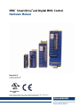
MMC
©
Smart Drive
TM
and Digital MMC Control
Hardware Manual
Keep all product manuals as a product component during the life span of the product.
Pass all product manuals to future users/owners of the product.
Version 6.0
Catalog No. M.1301.5524
Part No. M.3000.1329
IND. CONT. EQ.
12KP


Kollmorgen - December 2011 1
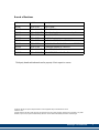
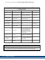
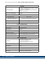
Record of Revisions
Third party brands and trademarks are the property of their respective owners
Technical changes to improve the performance of the equipment may be made without notice!
Printed in USA
All rights reserved. No part of this work may be reproduced in any form (by printing, photocopying, microfilm or any other
method) or processed, copied or distributed by electronic means without the written permission of Kollmorgen.
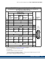
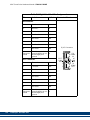
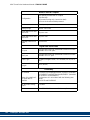
Edition Valid for Description
03/2007 PiCPro V16.1 Major Update
10/2007 PiCPro V16.1 SP2 Added MMC-D8
05/2008 PiCPro V16.1 SP3 Added 4 analog drives, various manual updates
09/2008 PiCPro V17.0 Added S200-DLS Drives
12/2008 PiCPro V17.0 Rev 1 fixed various typos
01/2009 PiCPro V17.0 Rev 2 added CE/UL info to S200-DLS
03/2009 PiCPro V17.0 Rev 3 added Aux Feedback Connector to S200DLS
02/2010 PiCPro V18.0 Kollmorgen Branding & S200 BiSS
03/2011 PiCPro V18.0 SP1 Added 230V, 3-Phase Drives
01/05/12 PiCPro V18.0 SP2 Added 460V, 3-Phase NextGen Drives

2 Kollmorgen - December 2011
NOTE
These products are being manufactured and sold by G & L Motion Control, Inc., a Kollmorgen
company.
Progress is an on-going commitment at Kollmorgen. We continually strive to offer the most advanced
products in the industry; therefore, information in this document is subject to change without notice.
The text and illustrations are not binding in detail. Kollmorgen shall not be liable for any technical or
editorial omissions occurring in this document, nor for any consequential or incidental damages
resulting from the use of this document.
Kollmorgen makes every attempt to ensure accuracy and reliability of the specifications in this
publication. Specifications are subject to change without notice. Kollmorgen provides this information
“AS IS” and disclaims all warranties, express or implied, including, but not limited to, implied
warranties of merchantability and fitness for a particular purpose. It is the responsibility of the product
user to determine the suitability of this product for a specific application.
DO NOT ATTEMPT to use any Kollmorgen product until the use of such product is completely
understood. It is the responsibility of the user to make certain proper operation practices are
understood. Kollmorgen products should be used only by qualified personnel and for the express
purpose for which said products were designed.
Should information not covered in this document be required, contact the Customer Service
Department, Kollmorgen, 672 South Military Road, P.O. Box 1960, Fond du Lac, WI 54936-1960.
Kollmorgen can be reached by telephone at (920) 921-7100 or (800) 558-4808 in the United States or
by e-mail at glmotion.suppor[email protected]m.
Catalog No. (Order No.) M.1301.5524
Printed Version Part No. M.3000.1329
Electronic Version Part No. M.3000.1328
Release 01042012
©2012, Kollmorgen

Kollmorgen - December 2011 3
MMC Smart Drive Hardware Manual - TABLE OF CONTENTS
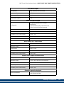
Table of Contents
Table of Contents................................................................................................................................3
1 Introduction to the MMC Smart Drive.............................................................................................9
1.1 Overview...................................................................................................................................9
1.2 Contents of This Manual...........................................................................................................9
1.3 Software and Manuals..............................................................................................................9
1.3.1 Required Software and Manuals.....................................................................................9
1.3.2 Suggested Manuals ........................................................................................................9
1.4 Kollmorgen Support Contact ..................................................................................................11
2 Safety Precautions.........................................................................................................................13
2.1 System Safety ........................................................................................................................13
2.1.1 User Responsibility .......................................................................................................13
2.1.2 Safety Instructions.........................................................................................................13
2.2 Safety Signs ...........................................................................................................................14
2.3 Warning Labels.......................................................................................................................14
2.4 Safety First .............................................................................................................................15
2.5 Safety Inspection....................................................................................................................15
2.5.1 Before Starting System.................................................................................................15
2.6 After Shutdown.......................................................................................................................15
2.7 Operating Safely.....................................................................................................................16
2.8 Electrical Service & Maintenance Safety................................................................................16
2.9 Safe Cleaning Practices .........................................................................................................17
3 Installing the MMC Smart Drive....................................................................................................19
3.1 Storing the Drive Before Installation ......................................................................................19
3.2 Unpacking the Drive ...............................................................................................................19
3.3 Handling an MMC Smart Drive...............................................................................................19
3.4 Inspecting the Drive Before Installation..................................................................................19
3.5 Complying with European Directives......................................................................................20
3.6 Conforming with UL and cUL Standards ................................................................................20
3.7 General Installation and Ventilation Requirements ................................................................20
3.8 Controlling Heat Within the System........................................................................................21
3.9 Bonding .................................................................................................................................22
3.9.1 Bonding a Subpanel Using a Stud................................................................................22
3.9.2 Bonding a Ground Bus Using a Stud............................................................................22
3.9.3 Bonding a Ground Bus or Chassis Using a Bolt ...........................................................22
3.9.4 Grounding Multiple Drive Cabinets ...............................................................................23
3.9.5 Bonding Multiple Subpanels..........................................................................................23
3.10 Drive Mounting Guidelines ...................................................................................................23
3.11 Drive System Grounding Procedures...................................................................................24
3.11.2 Grounding Multiple Drives in the Same Cabinet.........................................................27
3.12 System Wiring Guidelines ....................................................................................................27
3.12.1 Recommended Signal Separation ..............................................................................28
3.12.2 Building Your Own Cables..........................................................................................30
3.12.3 Routing Cables............................................................................................................30
3.13 Wiring the Drive....................................................................................................................30
3.13.1 Sizing the 24V Power Supply......................................................................................30
3.13.2 System AC Power Wiring Guidelines .........................................................................31
3.13.3 Connecting Interface Cables ......................................................................................32
3.13.4 Preparing Motor Connection Wires ............................................................................33

4 Kollmorgen - Decamber 2011
MMC Smart Drive Hardware Manual - TABLE OF CONTENTS
4 System Power Devices ................................................................................................................. 37
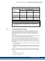
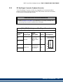
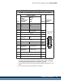
4.1 AC Input Power Requirements............................................................................................... 37
4.2 Protection............................................................................................................................... 39
4.2.1 Motor Overload Protection............................................................................................ 39
4.2.2 Motor Thermal Protection............................................................................................. 39
4.2.3 230V Smart Drive Protection Requirements................................................................. 39
4.2.4 460V Smart Drive Protection Requirements................................................................. 40
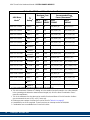
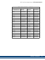
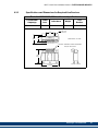
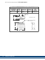
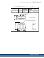
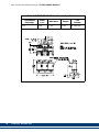
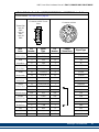
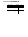
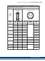
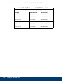
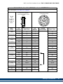
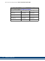
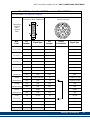
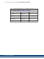
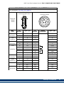
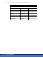
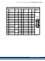
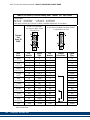
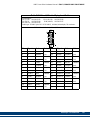
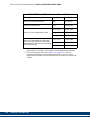
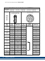
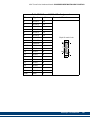
4.3 Line Reactors......................................................................................................................... 44
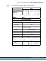
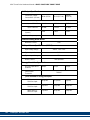
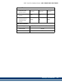
4.3.1 Specifications and Dimensions for Required Line Reactors......................................... 45
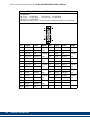
4.4 Isolation Transformers ........................................................................................................... 51
4.5 External Shunts...................................................................................................................... 52
4.5.1 Choosing External Shunts............................................................................................ 52
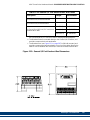
4.5.2 Mounting External Shunts ............................................................................................ 54
4.5.3 Connecting Shunt Modules .......................................................................................... 61
4.5.3.1 230V, 1-Phase MMC Smart Drive Shunt Wiring................................................. 61
4.5.3.2 460V, 3-Phase MMC Smart Drive (-SD) Shunt Wiring........................................ 62
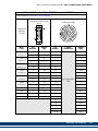
4.6 Line Filters.............................................................................................................................. 63
4.6.1 Line Filters and CE Compliance................................................................................... 63
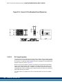
4.6.2 Dimensions for 230V Line Filters.................................................................................. 69
4.6.3 Dimensions for 460V Line Filters.................................................................................. 70
5 230V 1/3 Phase MMC Smart Drive................................................................................................ 71
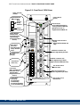
5.1 Control Section Connectors, Switches, LEDs........................................................................ 73
5.1.1 LEDs............................................................................................................................. 73
5.1.2 PiCPro Port (Digital Interfaced Drives)......................................................................... 73
5.1.3 PiCPro Port (Analog Drives)......................................................................................... 75
5.1.4 Node Address Rotary Switch (Digital Interfaced MMC-SD Only)................................. 78
5.1.5 Digital Link Ports (Digital Interfaced MMC-SD Only).................................................... 79
5.1.6 Feedback Connectors (F1 & F2) .................................................................................. 81
5.1.6.1 Feedback Connectors (F1 and F2) Details ......................................................... 86
5.1.6.2 Feedback Port (F1/F2) to Motor Cables.............................................................. 90
5.1.7 Drive I/O Connector (IO)............................................................................................. 102
5.2 Power Section Connectors...................................................................................................109
5.2.1 24 VDC IN/Brake Connector ...................................................................................... 110
5.2.1.1 "EN" requirements and Safe-off Operation ....................................................... 111
5.2.2 Power Connector........................................................................................................ 112
5.2.3 DC Bus/Regen Connector (3-phase drive only) ......................................................... 115
5.3 Specifications - 230V MMC Smart Drive.............................................................................. 116
5.3.1 General Data for all 230V Models ............................................................................. 116
5.3.2 Physical and Electrical Data for 230V Drives ............................................................. 119
5.4 Dimensions for 230V MMC Smart Drive.............................................................................. 120
6 460V 3 Phase MMC Smart Drive NextGen................................................................................. 127
6.1 Control Section Connectors, Switches, LEDs...................................................................... 130
6.1.1 Status Display............................................................................................................. 130
6.1.2 Node Address Rotary Switches.................................................................................. 130
6.1.3 Digital Link Ports......................................................................................................... 131
6.1.4 Feedback Connectors (F1 & F2) ................................................................................ 133
6.1.4.1 Feedback Connectors (F1 and F2) Details ....................................................... 138
6.1.4.2 Feedback Port (F1/F2) to Motor Cables............................................................ 143
6.1.5 Drive I/O Connectors (IO1 & IO2)............................................................................... 148
6.2 Power Section Connectors...................................................................................................152
6.2.1 DC Power Connector.................................................................................................. 152
6.2.1.1 "EN" requirements and Safe-off Operation ....................................................... 152

Kollmorgen - December 2011 5
MMC Smart Drive Hardware Manual - TABLE OF CONTENTS
6.2.2 AC Power Connector ..................................................................................................153
6.2.2.1 Line Fusing........................................................................................................153
6.2.3 Motor/Brake Connector...............................................................................................154
6.2.3.1 Motor/Brake Cables...........................................................................................156
6.2.3.2 Motor Chokes ....................................................................................................156
6.2.4 DC Bus/Regen Connector...........................................................................................157
6.2.4.1 Bus/Regen Connections....................................................................................157
6.2.4.2 External Regen Resistors..................................................................................157
6.3 Specifications - 460V MMC Smart Drive NextGen...............................................................159
6.3.1 General Data...............................................................................................................159
6.3.2 Physical and Electrical Data........................................................................................163
6.4 Dimensions...........................................................................................................................164
7 460V 3-Phase MMC Smart Drive.................................................................................................167
7.1 Control Section Connectors, Switches, LEDs ......................................................................167
7.2 Power Section Connectors...................................................................................................167
7.2.1 Size 1 Power Section Connectors...............................................................................167
7.2.1.1 Shunt/DC Bus Connector .................................................................................169
7.2.1.2 AC Power Connector ........................................................................................170
7.2.1.3 Motor Connector................................................................................................170
7.2.1.4 24V Power Connector (J1) ................................................................................171
7.2.1.5 Motor Brake Connector (X101) .........................................................................172
7.2.2 Size 2 Power Section Connectors...............................................................................172
7.2.2.1 AC Power Connector.........................................................................................174
7.2.2.2 Motor Connector................................................................................................175
7.2.2.3 24V Power Connector (J1) ................................................................................176
7.2.3 Size 3 Power Section Connectors...............................................................................177
7.2.3.1 AC Power Connector.........................................................................................179
7.2.3.2 Motor Connector................................................................................................180
7.2.3.3 24V Power Connector (J1) ................................................................................181
7.2.3.4 Motor Brake Connector (X101)..........................................................................182
7.2.4 Size 4 Power Section Connectors...............................................................................182
7.2.4.1 AC Power Connector ........................................................................................184
7.2.4.2 Motor Connector................................................................................................185
7.2.4.3 24V Power Connector (J1) ................................................................................186
7.2.4.4 Motor Brake Connector (X101)..........................................................................187
7.2.4.5 Fan Connector (X36).........................................................................................188
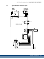
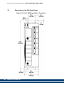
7.3 Typical 460V Drive Connection Layout ................................................................................189
7.4 Specifications - 460V MMC Smart Drive).............................................................................190
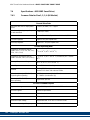
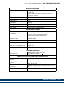
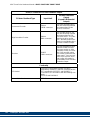
7.4.1 Common Data for Size 1, 2, 3, 4 (All Models).............................................................190
7.4.2 Physical/Electrical Data for 460V Size 1 Smart Drives...............................................193
7.4.3 Physical/Electrical Data for 460V Size 2 Smart Drives...............................................195
7.4.4 Physical/Electrical Data for 460V Size 3 Smart Drives...............................................198
7.4.5 Physical/Electrical Data for 460V Size 4 Smart Drives...............................................201
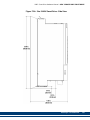
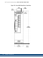
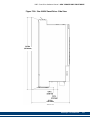
7.5 Dimensions for the 460V Smart Drives ...............................................................................204
8 S200-DLS Drive ............................................................................................................................213
8.1 S200-DLS Option Card.........................................................................................................215
8.1.1 LED Indicators.............................................................................................................215
8.1.2 Diagnostic Indicator Details.........................................................................................215
8.1.3 Digital Link LEDs.........................................................................................................215
8.1.4 Node Address Rotary Switches ..................................................................................216
8.1.5 Digital Link Ports.........................................................................................................217
8.1.6 Auxiliary Feedback Port..............................................................................................219

6 Kollmorgen - Decamber 2011
MMC Smart Drive Hardware Manual - TABLE OF CONTENTS
8.1.7 Drive I/O and I/O Power Ports.................................................................................... 227
8.1.8 Drive I/O Port Details.................................................................................................. 229
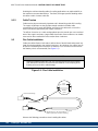
8.1.8.1 Drive I/O Port Outputs....................................................................................... 230
8.1.8.2 Drive I/O Port Inputs.......................................................................................... 230
8.1.8.3 Drive I/O Port Wiring Example.......................................................................... 230
8.2 Power Section Wiring Accessories ...................................................................................... 231
8.3 Specifications - S200-DLS Drive.......................................................................................... 233
9 Motor Cables & Connectors ....................................................................................................... 235
9.1 Flex Cable Installation Guidelines........................................................................................ 235
9.1.1 Bending Radius.......................................................................................................... 235
9.1.2 Cable Tension ............................................................................................................236
9.2 Flex Cable Installation.......................................................................................................... 236
9.3 AKM/DDR Motor Power Cables........................................................................................... 238
9.4 LSM/MSM Motor Connector Kits ......................................................................................... 239
9.5 LSM/MSM Motor Power Cables........................................................................................... 240
9.6 LSM/MSM Motor Fan Cables............................................................................................... 243
10 Maintenance and Troubleshooting.......................................................................................... 245
10.1 Maintenance ...................................................................................................................... 245
10.2 Troubleshooting ................................................................................................................. 246
10.2.1 General Troubleshooting.......................................................................................... 246
10.2.2 Power LED ...............................................................................................................246
10.2.3 Power-On Diagnostics.............................................................................................. 246
10.2.4 Run-Time Diagnostics .............................................................................................. 246
10.2.4.1 Troubleshooting with the Diagnostic LED (D1)............................................... 247
10.2.4.2 Troubleshooting with the 7-Segment Display.................................................. 247
10.2.4.3 Troubleshooting using the Status LED (STATUS).......................................... 255
11 Resolver Interface Option Module........................................................................................... 259
11.1 Theory of Operation........................................................................................................... 259
11.2 Installing the Resolver Module........................................................................................... 259
12 Drive Resident Digital MMC Control........................................................................................ 263
12.1 Introduction ........................................................................................................................ 263
12.1.1 Overview................................................................................................................... 263
12.1.2 Major Components ................................................................................................... 263
12.2 Installing the Drive Resident Digital MMC Control............................................................. 265
12.2.1 Installing into a 230V MMC-SD Drive....................................................................... 265
12.2.2 Installing into a 460V MMC-SD Drive....................................................................... 265
12.3 System Wiring Guidelines..................................................................................................266
12.4 Starting an Operation......................................................................................................... 267
12.4.1 Connecting the Drive Resident Digital MMC Control to the Application................... 267
12.4.2 Basic Setup and Maintenance Procedures .............................................................. 267
12.4.3 Start-up Diagnostics ................................................................................................. 268
12.4.3.1 Power LED...................................................................................................... 268
12.4.3.2 Scan LED........................................................................................................ 268
12.4.3.3 Drive Resident Digital MMC Control Start-Up Diagnostic LEDs ..................... 269
12.4.4 MMC Run-Time Diagnostics..................................................................................... 270
12.5 Connectors & Operation..................................................................................................... 271
12.5.1 PiCPro Port (P1)....................................................................................................... 271
12.5.2 Block I/O Port (C1) ................................................................................................... 271
12.5.3 User Port .................................................................................................................. 275
12.5.4 Ethernet Port ............................................................................................................ 281

Kollmorgen - December 2011 7
MMC Smart Drive Hardware Manual - TABLE OF CONTENTS
12.5.5 General I/O Port (C5)................................................................................................283
12.5.5.1 DC Output Operation.......................................................................................288
12.5.5.2 DC Input Operation..........................................................................................290
12.6 Specifications ....................................................................................................................292
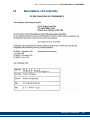
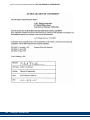
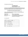
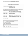
13 Declarations of Conformity.......................................................................................................295
A 460V MMC Smart Drive DC Bus Sharing...................................................................................301
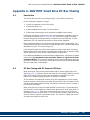
A.1 Introduction ..........................................................................................................................301
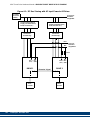
A.2 DC Bus Sharing with AC Power to All Drives.......................................................................301
A.3 DC Bus Sharing with AC Power to One Drive......................................................................303
B 460V MMC Smart Drive DC Bus Sharing...................................................................................307
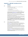
B.1 Introduction ..........................................................................................................................307
B.2 DC Bus Sharing with AC Power to All Drives.......................................................................307
B.3 DC Bus Sharing with AC Power to One Drive......................................................................309
Index.................................................................................................................................................313
Sales and Service............................................................................................................................319

8 Kollmorgen - Decamber 2011
MMC Smart Drive Hardware Manual - TABLE OF CONTENTS

Kollmorgen - December 2011 9
MMC Smart Drive Hardware Manual - INTRODUCTION TO THE MMC SMART DRIVE
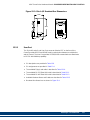
1 Introduction to the MMC Smart Drive
1.1 Overview
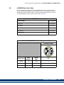
This manual covers four distinct products:
• The Analog and Digital Interfaced 230V MMC Smart Drive (MMC-SD). The 230V
Smart Drive is detailed exclusively in Chapter 5 on page 71
• The Digital 460V Smart Drive NextGen. The 460V Smart Drive NextGen is
detailed exclusively in Chapter 6 on page 127
• The Analog and Digital Interfaced 460V MMC Smart Drive (MMC-SD). The 460V
Smart Drive is detailed exclusively in Chapter 7 on page 167
• The S200-DLS Digital Link Drive which receives motion commands via a digital
connection (Digital Link)
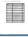
1.2 Contents of This Manual
This manual includes the following major topics:
• Information to safely operate and maintain the equipment in a safe manner.
• User responsibilities for product acceptance and storage.
• Power and environmental information for general power, control cabinet, ground-
ing, heat control and handling.
• Procedures for mounting, wiring, and connecting the MMC Smart Drive and stan-
dard Kollmorgen motors recommended for use with the MMC Smart Drive.
• Recommended drive system wiring guidelines for signal separation and differen-
tial devices. Methods to ensure ElectroMagnetic Compatibility.
• The location of connectors on the drive and descriptions of their functionality
including I/O, encoder, serial interface and motor/brake connector locations and
signal descriptions.
• Physical, electrical, environmental and functional specifications/dimensions.
• Description of the minimal maintenance necessary.
• A troubleshooting chart of potential problems and possible solutions.
• Part numbers and descriptions for the drive and related equipment.
1.3 Software and Manuals
1.3.1 Required Software and Manuals
PiCPro (one of the following)
• Professional Edition
• MMC Limited Edition
• Monitor Edition
1.3.2 Suggested Manuals
• Function/Function Block Reference Guide
• Motion Application Specific Function Block Manual

10 Kollmorgen - December 2011
MMC Smart Drive Hardware Manual - INTRODUCTION TO THE MMC SMART DRIVE
• Ethernet Application Specific Function Block Manual
• General Purpose Application Specific Function Block
Manual

Kollmorgen - December 2011 11
MMC Smart Drive Hardware Manual - INTRODUCTION TO THE MMC SMART DRIVE
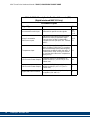
1.4 Kollmorgen Support Contact
Contact your local Kollmorgen representative for:
• Sales and order support
• Product technical training
• Warranty support
• Support service agreements
Kollmorgen Technical Support can be reached:
• In the United States, telephone (800) 558-4808
• Outside the United States, telephone (920) 921-7100
• E-mail address: glmotion.supp[email protected]
• Web site: www.kollmorgen.com

12 Kollmorgen - December 2011
MMC Smart Drive Hardware Manual - INTRODUCTION TO THE MMC SMART DRIVE

Kollmorgen - December 2011 13
MMC Smart Drive Hardware Manual - SAFETY PRECAUTIONS
2 Safety Precautions
READ AND UNDERSTAND THIS SECTION IN ITS ENTIRETY
BEFORE UNDERTAKING INSTALLATION OR ADJUSTMENT OF
THE MMC SMART DRIVE AND ANY ASSOCIATED SYSTEMS OR
EQUIPMENT
The instructions contained in this section will help users to operate and maintain the
equipment in a safe manner.
PLEASE REMEMBER THAT SAFETY IS EVERYONE'S
RESPONSIBILITY
2.1 System Safety
The basic rules of safety set forth in this section are intended as a guide for the safe
operation of equipment. This general safety information, along with explicit service,
maintenance and operational materials, make up the complete instruction set. All
personnel who operate, service or are involved with this equipment in any way should
become totally familiar with this information prior to operating.
2.1.1 User Responsibility
It is the responsibility of the user to ensure that the procedures set forth here are
followed and, should any major deviation or change in use from the original
specifications be required, appropriate procedures should be established for the
continued safe operation of the system. It is strongly recommended that you contact
your OEM to ensure that the system can be safely converted for its new use and
continue to operate in a safe manner.
2.1.2 Safety Instructions
• Do not operate your equipment with safety devices bypassed or covers removed.
• Only qualified personnel should operate the equipment.
• Never perform service or maintenance while automatic control sequences are in
operation.
• To avoid shock or serious injury, only qualified personnel should perform mainte-
nance on the system.

14 Kollmorgen - December 2011
MMC Smart Drive Hardware Manual - SAFETY PRECAUTIONS
• GROUNDING (Protective Earth)
The equipment must be grounded (connected to the protective earth connection)
according to OEM recommendations and to the latest local regulations for electrical
safety. The grounding (protective earth) conductor must not be interrupted inside or
outside the equipment enclosures. The wire used for equipment grounding
(connection to protective earth) should be green with a yellow stripe.
2.2 Safety Signs
The purpose of a system of safety signs is to draw attention to objects and situations
which could affect personal or plant safety. It should be noted that the use of safety
signs does not replace the need for appropriate accident prevention measures.
Always read and follow the instructions based upon the level of hazard or potential
danger.
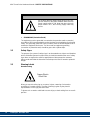
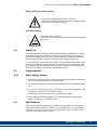
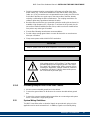
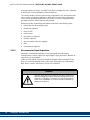
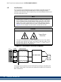
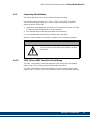
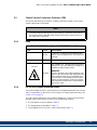
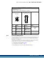
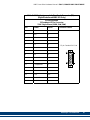
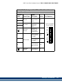
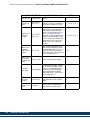
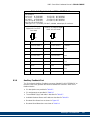
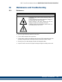
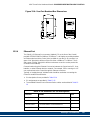
2.3 Warning Labels
Hazard warning
When you see this safety sign on a system, it gives a warning of a hazard or
possibility of a hazard existing. The type of warning is given by the pictorial
representation on the sign plus text if used.
To ignore such a caution could lead to severe injury or death arising from an unsafe
practice.
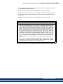
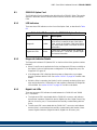
ATTENTION
Do not touch the main power supply fuses or any com-
ponents internal to the power modules while the main
power supply switch is ON. Note that when the main
power switch is OFF, the incoming supply cable may
be live.
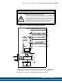
Danger Electric
Shock Risk

Kollmorgen - December 2011 15
MMC Smart Drive Hardware Manual - SAFETY PRECAUTIONS
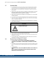
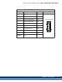
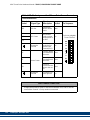
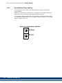
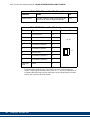
Danger, Warning, or Caution warning
Hot Surface warning
2.4 Safety First
Kollmorgen equipment is designed and manufactured with consideration and care to
generally accepted safety standards. However, the proper and safe performance of
the equipment depends upon the use of sound and prudent operating, maintenance
and servicing procedures by trained personnel under adequate supervision.
For your protection, and the protection of others, learn and always follow these safety
rules. Observe warnings on machines and act accordingly. Form safe working habits
by reading the rules and abiding by them. Keep these safety rules handy and review
them from time to time to refresh your understanding of them.
2.5 Safety Inspection
2.5.1 Before Starting System
• Ensure that all guards and safety devices are installed and operative and all doors
which carry warning labels are closed and locked.
• Ensure that all personnel are clear of those areas indicated as potentially hazard-
ous.
• Remove (from the operating zone) any materials, tools or other objects that could
cause injury to personnel or damage the system.
• Make sure that the control system is in an operational condition.
• Make certain that all indicating lights, horns, pressure gauges or other safety
devices or indicators are in working order.
2.6 After Shutdown
Make certain all controlled equipment in the plant is safe and the associated electrical,
pneumatic or hydraulic power is turned off. It is permissible for the control equipment
contained in enclosures to remain energized provided this does not conflict with the
safety instructions found in this section.
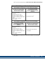
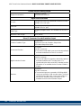
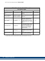
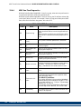
Symbol plus DANGER, WARNING or CAUTION:
These notices provide information intended to prevent potential
sonal injury and equipment damage.
Symbol plus HOT SURFACE:
These notices provide information intended to prevent potential p
e
sonal injury.

16 Kollmorgen - December 2011
MMC Smart Drive Hardware Manual - SAFETY PRECAUTIONS
2.7 Operating Safely
• Do not operate the control system until you read and understand the operating
instructions and become thoroughly familiar with the system and the controls.
• Never operate the control system while a safety device or guard is removed or
disconnected
• Where access to the control system is permitted for manual operation, only those
doors which provide that access should be unlocked. They should be locked
immediately after the particular operation is completed.
• Never remove warnings that are displayed on the equipment. Torn or worn labels
should be replaced.
• Do not start the control system until all personnel in the area have been warned.
• Never sit or stand on anything that might cause you to fall onto the control equip-
ment or its peripheral equipment.
• Horseplay around the control system and its associated equipment is dangerous
and should be prohibited.
• Never operate the equipment outside specification limits.
• Keep alert and observe indicator lights, system messages and warnings that are
displayed on the system.
• Do not operate faulty or damaged equipment. Make certain proper service and
maintenance procedures have been performed.
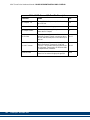
2.8 Electrical Service & Maintenance Safety
• ALL ELECTRICAL OR ELECTRONIC MAINTENANCE AND SERVICE
SHOULD BE PERFORMED BY TRAINED AND AUTHORIZED PERSONNEL
ONLY.
• It should be assumed at all times that the POWER is ON and all conditions treated
as live. This practice assures a cautious approach which may prevent accident or
injury.
• To remove power:
LOCK THE SUPPLY CIRCUIT DISCONNECTING MEANS IN THE OPEN POSI-
TION.
APPLY LOCKOUT/TAGOUT DEVICES IN ACCORDANCE WITH A DOCU-
MENTED AND ESTABLISHED POLICY.
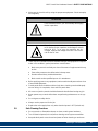
ATTENTION
Know the emergency stop
procedures for the system.

Kollmorgen - December 2011 17
MMC Smart Drive Hardware Manual - SAFETY PRECAUTIONS
• Make sure the circuit is safe by using the proper test equipment. Check test equip-
ment regularly.
• There may be circumstances where troubleshooting on live equipment is required.
Under such conditions, special precautions must be taken:
• Make sure your tools and body are clear of the areas of equipment which may
be live.
• Extra safety measures should be taken in damp areas.
• Be alert and avoid any outside distractions.
• Make certain another qualified person is in attendance.
• Before applying power to any equipment, make certain that all personnel are clear
of associated equipment.
• Control panel doors should be unlocked only when checking out electrical equip-
ment or wiring. On completion, close and lock panel doors.
• All covers on junction panels should be fastened closed before leaving any job.
• Never operate any controls while others are performing maintenance on the sys-
tem.
• Do not bypass a safety device.
• Always use the proper tool for the job.
• Replace the main supply fuses only when electrical power is OFF (locked out).
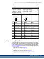
2.9 Safe Cleaning Practices
• Do not use toxic or flammable solvents to clean control system hardware.
• Turn off electrical power (lock out) before cleaning control system assemblies.
• Keep electrical panel covers closed and power off when cleaning an enclosure.
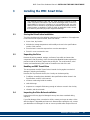
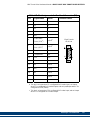
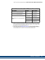
ATTENTION
Care should be taken if you are manually discharging
the bus capacitors.
WARNING
Even after power to the drive is removed, it may take up
to 10 minutes for bus capacitors to discharge to a level
below 50 VDC. To be sure the capacitors are dis-
charged, measure the voltage across the + and - termi-
nals for the DC bus.

18 Kollmorgen - December 2011
MMC Smart Drive Hardware Manual - SAFETY PRECAUTIONS
• Always clean up spills around the equipment immediately after they occur.
• Never attempt to clean a control system while it is operating.
• Never use water to clean control equipment unless you are certain that the equip-
ment has been certified as sealed against water ingress. Water is a very good
conductor of electricity and the single largest cause of death by electrocution.
Page is loading ...
Page is loading ...
Page is loading ...
Page is loading ...
Page is loading ...
Page is loading ...
Page is loading ...
Page is loading ...
Page is loading ...
Page is loading ...
Page is loading ...
Page is loading ...
Page is loading ...
Page is loading ...
Page is loading ...
Page is loading ...
Page is loading ...
Page is loading ...
Page is loading ...
Page is loading ...
Page is loading ...
Page is loading ...
Page is loading ...
Page is loading ...
Page is loading ...
Page is loading ...
Page is loading ...
Page is loading ...
Page is loading ...
Page is loading ...
Page is loading ...
Page is loading ...
Page is loading ...
Page is loading ...
Page is loading ...
Page is loading ...
Page is loading ...
Page is loading ...
Page is loading ...
Page is loading ...
Page is loading ...
Page is loading ...
Page is loading ...
Page is loading ...
Page is loading ...
Page is loading ...
Page is loading ...
Page is loading ...
Page is loading ...
Page is loading ...
Page is loading ...
Page is loading ...
Page is loading ...
Page is loading ...
Page is loading ...
Page is loading ...
Page is loading ...
Page is loading ...
Page is loading ...
Page is loading ...
Page is loading ...
Page is loading ...
Page is loading ...
Page is loading ...
Page is loading ...
Page is loading ...
Page is loading ...
Page is loading ...
Page is loading ...
Page is loading ...
Page is loading ...
Page is loading ...
Page is loading ...
Page is loading ...
Page is loading ...
Page is loading ...
Page is loading ...
Page is loading ...
Page is loading ...
Page is loading ...
Page is loading ...
Page is loading ...
Page is loading ...
Page is loading ...
Page is loading ...
Page is loading ...
Page is loading ...
Page is loading ...
Page is loading ...
Page is loading ...
Page is loading ...
Page is loading ...
Page is loading ...
Page is loading ...
Page is loading ...
Page is loading ...
Page is loading ...
Page is loading ...
Page is loading ...
Page is loading ...
Page is loading ...
Page is loading ...
Page is loading ...
Page is loading ...
Page is loading ...
Page is loading ...
Page is loading ...
Page is loading ...
Page is loading ...
Page is loading ...
Page is loading ...
Page is loading ...
Page is loading ...
Page is loading ...
Page is loading ...
Page is loading ...
Page is loading ...
Page is loading ...
Page is loading ...
Page is loading ...
Page is loading ...
Page is loading ...
Page is loading ...
Page is loading ...
Page is loading ...
Page is loading ...
Page is loading ...
Page is loading ...
Page is loading ...
Page is loading ...
Page is loading ...
Page is loading ...
Page is loading ...
Page is loading ...
Page is loading ...
Page is loading ...
Page is loading ...
Page is loading ...
Page is loading ...
Page is loading ...
Page is loading ...
Page is loading ...
Page is loading ...
Page is loading ...
Page is loading ...
Page is loading ...
Page is loading ...
Page is loading ...
Page is loading ...
Page is loading ...
Page is loading ...
Page is loading ...
Page is loading ...
Page is loading ...
Page is loading ...
Page is loading ...
Page is loading ...
Page is loading ...
Page is loading ...
Page is loading ...
Page is loading ...
Page is loading ...
Page is loading ...
Page is loading ...
Page is loading ...
Page is loading ...
Page is loading ...
Page is loading ...
Page is loading ...
Page is loading ...
Page is loading ...
Page is loading ...
Page is loading ...
Page is loading ...
Page is loading ...
Page is loading ...
Page is loading ...
Page is loading ...
Page is loading ...
Page is loading ...
Page is loading ...
Page is loading ...
Page is loading ...
Page is loading ...
Page is loading ...
Page is loading ...
Page is loading ...
Page is loading ...
Page is loading ...
Page is loading ...
Page is loading ...
Page is loading ...
Page is loading ...
Page is loading ...
Page is loading ...
Page is loading ...
Page is loading ...
Page is loading ...
Page is loading ...
Page is loading ...
Page is loading ...
Page is loading ...
Page is loading ...
Page is loading ...
Page is loading ...
Page is loading ...
Page is loading ...
Page is loading ...
Page is loading ...
Page is loading ...
Page is loading ...
Page is loading ...
Page is loading ...
Page is loading ...
Page is loading ...
Page is loading ...
Page is loading ...
Page is loading ...
Page is loading ...
Page is loading ...
Page is loading ...
Page is loading ...
Page is loading ...
Page is loading ...
Page is loading ...
Page is loading ...
Page is loading ...
Page is loading ...
Page is loading ...
Page is loading ...
Page is loading ...
Page is loading ...
Page is loading ...
Page is loading ...
Page is loading ...
Page is loading ...
Page is loading ...
Page is loading ...
Page is loading ...
Page is loading ...
Page is loading ...
Page is loading ...
Page is loading ...
Page is loading ...
Page is loading ...
Page is loading ...
Page is loading ...
Page is loading ...
Page is loading ...
Page is loading ...
Page is loading ...
Page is loading ...
Page is loading ...
Page is loading ...
Page is loading ...
Page is loading ...
Page is loading ...
Page is loading ...
Page is loading ...
Page is loading ...
Page is loading ...
Page is loading ...
Page is loading ...
Page is loading ...
Page is loading ...
Page is loading ...
Page is loading ...
Page is loading ...
Page is loading ...
Page is loading ...
Page is loading ...
Page is loading ...
Page is loading ...
Page is loading ...
Page is loading ...
Page is loading ...
Page is loading ...
Page is loading ...
Page is loading ...
Page is loading ...
Page is loading ...
Page is loading ...
Page is loading ...
Page is loading ...
Page is loading ...
Page is loading ...
Page is loading ...
Page is loading ...
Page is loading ...
Page is loading ...
Page is loading ...
Page is loading ...
Page is loading ...
Page is loading ...
Page is loading ...
Page is loading ...
Page is loading ...
Page is loading ...
Page is loading ...
Page is loading ...
Page is loading ...
Page is loading ...
-
 1
1
-
 2
2
-
 3
3
-
 4
4
-
 5
5
-
 6
6
-
 7
7
-
 8
8
-
 9
9
-
 10
10
-
 11
11
-
 12
12
-
 13
13
-
 14
14
-
 15
15
-
 16
16
-
 17
17
-
 18
18
-
 19
19
-
 20
20
-
 21
21
-
 22
22
-
 23
23
-
 24
24
-
 25
25
-
 26
26
-
 27
27
-
 28
28
-
 29
29
-
 30
30
-
 31
31
-
 32
32
-
 33
33
-
 34
34
-
 35
35
-
 36
36
-
 37
37
-
 38
38
-
 39
39
-
 40
40
-
 41
41
-
 42
42
-
 43
43
-
 44
44
-
 45
45
-
 46
46
-
 47
47
-
 48
48
-
 49
49
-
 50
50
-
 51
51
-
 52
52
-
 53
53
-
 54
54
-
 55
55
-
 56
56
-
 57
57
-
 58
58
-
 59
59
-
 60
60
-
 61
61
-
 62
62
-
 63
63
-
 64
64
-
 65
65
-
 66
66
-
 67
67
-
 68
68
-
 69
69
-
 70
70
-
 71
71
-
 72
72
-
 73
73
-
 74
74
-
 75
75
-
 76
76
-
 77
77
-
 78
78
-
 79
79
-
 80
80
-
 81
81
-
 82
82
-
 83
83
-
 84
84
-
 85
85
-
 86
86
-
 87
87
-
 88
88
-
 89
89
-
 90
90
-
 91
91
-
 92
92
-
 93
93
-
 94
94
-
 95
95
-
 96
96
-
 97
97
-
 98
98
-
 99
99
-
 100
100
-
 101
101
-
 102
102
-
 103
103
-
 104
104
-
 105
105
-
 106
106
-
 107
107
-
 108
108
-
 109
109
-
 110
110
-
 111
111
-
 112
112
-
 113
113
-
 114
114
-
 115
115
-
 116
116
-
 117
117
-
 118
118
-
 119
119
-
 120
120
-
 121
121
-
 122
122
-
 123
123
-
 124
124
-
 125
125
-
 126
126
-
 127
127
-
 128
128
-
 129
129
-
 130
130
-
 131
131
-
 132
132
-
 133
133
-
 134
134
-
 135
135
-
 136
136
-
 137
137
-
 138
138
-
 139
139
-
 140
140
-
 141
141
-
 142
142
-
 143
143
-
 144
144
-
 145
145
-
 146
146
-
 147
147
-
 148
148
-
 149
149
-
 150
150
-
 151
151
-
 152
152
-
 153
153
-
 154
154
-
 155
155
-
 156
156
-
 157
157
-
 158
158
-
 159
159
-
 160
160
-
 161
161
-
 162
162
-
 163
163
-
 164
164
-
 165
165
-
 166
166
-
 167
167
-
 168
168
-
 169
169
-
 170
170
-
 171
171
-
 172
172
-
 173
173
-
 174
174
-
 175
175
-
 176
176
-
 177
177
-
 178
178
-
 179
179
-
 180
180
-
 181
181
-
 182
182
-
 183
183
-
 184
184
-
 185
185
-
 186
186
-
 187
187
-
 188
188
-
 189
189
-
 190
190
-
 191
191
-
 192
192
-
 193
193
-
 194
194
-
 195
195
-
 196
196
-
 197
197
-
 198
198
-
 199
199
-
 200
200
-
 201
201
-
 202
202
-
 203
203
-
 204
204
-
 205
205
-
 206
206
-
 207
207
-
 208
208
-
 209
209
-
 210
210
-
 211
211
-
 212
212
-
 213
213
-
 214
214
-
 215
215
-
 216
216
-
 217
217
-
 218
218
-
 219
219
-
 220
220
-
 221
221
-
 222
222
-
 223
223
-
 224
224
-
 225
225
-
 226
226
-
 227
227
-
 228
228
-
 229
229
-
 230
230
-
 231
231
-
 232
232
-
 233
233
-
 234
234
-
 235
235
-
 236
236
-
 237
237
-
 238
238
-
 239
239
-
 240
240
-
 241
241
-
 242
242
-
 243
243
-
 244
244
-
 245
245
-
 246
246
-
 247
247
-
 248
248
-
 249
249
-
 250
250
-
 251
251
-
 252
252
-
 253
253
-
 254
254
-
 255
255
-
 256
256
-
 257
257
-
 258
258
-
 259
259
-
 260
260
-
 261
261
-
 262
262
-
 263
263
-
 264
264
-
 265
265
-
 266
266
-
 267
267
-
 268
268
-
 269
269
-
 270
270
-
 271
271
-
 272
272
-
 273
273
-
 274
274
-
 275
275
-
 276
276
-
 277
277
-
 278
278
-
 279
279
-
 280
280
-
 281
281
-
 282
282
-
 283
283
-
 284
284
-
 285
285
-
 286
286
-
 287
287
-
 288
288
-
 289
289
-
 290
290
-
 291
291
-
 292
292
-
 293
293
-
 294
294
-
 295
295
-
 296
296
-
 297
297
-
 298
298
-
 299
299
-
 300
300
-
 301
301
-
 302
302
-
 303
303
-
 304
304
-
 305
305
-
 306
306
-
 307
307
-
 308
308
-
 309
309
-
 310
310
-
 311
311
-
 312
312
-
 313
313
-
 314
314
-
 315
315
-
 316
316
-
 317
317
-
 318
318
-
 319
319
-
 320
320
-
 321
321
-
 322
322


Kollmorgen MMC Smart Drive User manual
- Type
- User manual
- This manual is also suitable for
Ask a question and I''ll find the answer in the document
Finding information in a document is now easier with AI
Related papers
-
Kollmorgen MMC-SD-72.0-460 User manual
-
-
-
-
-
-
-
-
-
Other documents
-
takeMS MS256MMC-MM3R Datasheet
-
 SEAV LG 2020 Owner's manual
-
SCE MOD84FTPT Saginaw Control and Engineering Operating instructions
-
Intelligent Motion Systems IM1007IE User manual
-
 Code 3 Matrix Switch Node Install Instructions
-
 Alarm Controls Corporation TS-2T Installation guide
-
CableWholesale 10U3-02115E Datasheet
-
DKS 1830 Series - RS232-RS422 Extender Kit 1830-190 User manual
-
 KegLand KB09073 Operating instructions
-
WAC Lighting Junction Box Canopy Operating instructions


