PD420/21 & PD460/61 4-20 mA Set Point Generator and Valve Positioner
www.predig.com
2
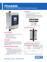
Index Designation Comments
F001
Output mode 0: Coarse tuning mode: use F004 to adjust increment value per click
1: Fine tuning mode: use F005 to adjust increment value per click
2: Quick output: use F100 to enter number of quick output settings
3: Automatic curve output: use F200 to enter number of curves
F002
Output range 0: 4-20 mA 1: 3-21 mA
F003
Display range 0: Current 1: 0-100% 2: 0-50%
F004
Coarse tuning Increment
Value
1-50 Addition and subtraction for each click. Disregard decimal point (1-50) x10
F005
Fine tuning increment value 1-50 Addition and subtraction for each click. Disregard decimal point (1-50) x10
F006
Auto save of adjustment
value
0: Not automatically saved. Need
to press knob to save
1: Automatic save
F007
Calibration Factory set only
Change from coarse to ne tuning mode:
1. Press and hold the knob for two seconds until F001 appears.
2. Press the knob again
3. Change the number from 0 (coarse tuning mode) to
1 (Fine tuning mode)
4. Press the knob again
Entering Passwords:
1. Rotate knob one click clockwise for “ ”
2. Rotate knob one click counter-clock for “-“
3. Press the knob to conrm
Change output range from 4-20 mA to 3-21 mA:
1. Enter the password as described above
2. The F002 menu is used to change the output range.
Turn knob until the desired parameter number appears
and press enter:
a. 0: 4-20 mA
b. 1: 3-21 mA
3. Keep turning the knob until FEnd appears and press the
knob to exit programming
Change display from current (4-20 or 3-21 mA)
to 0.0-100.0% or 0.0-50.0%:
1. Enter the password as described above
2. Turn the knob once clockwise and F003 appears.
3. Press the knob and turn the knob until the desired
parameter number appears and press enter:
a. 0: Current
b. 1: 0.0-100.0%
c. 2: 0.0-50.0%
4. Keep turning the know until FEnd appears and press the
knob to exit
Change the value for how much each click on
the knob adjusts coarse tuning:
1. Enter the password as described above
2. Turn the knob twice clockwise until F004 appears.
3. Press the knob and turn the knob until the number that
represents how much the display will change with each
click appears and press enter.
4. Keep turning the knob until FEnd appears and press the
knob to exit
Change the value for how much each click on
the knob adjusts ne tuning:
1. Enter the password as described above
2. Turn the knob three times clockwise until F005 appears.
3. Press the knob and turn the knob until the number that
represents how much the display will change with each
click appears and press enter.
4. Keep turning the know until FEnd appears and press the
knob to exit
Change from pressing the knob to save
programming to automatic save:
1. Enter the password as described above
2. Turn the knob four times clockwise until F006 appears.
3. Press the knob and turn the knob until the desired
parameter number appears and press enter:
a. 0: Need to press knob to save programming
b. 1: Automatic save
4. Keep turning the know until FEnd appears and press the
knob to exit
PROGRAMMING INSTRUCTIONS
Parameter Table 1: Entering F002-F007 (FXXX System Settings) requires a password “ -- ” rst:
+ +
Default Values Set Point Generator Valve Positioner
Coarse tuning mode Increments of 0.10 Increments of 1
Output range 4-20 mA 4-20 mA
Display mode 4-20 mA 0-100%