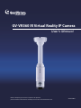
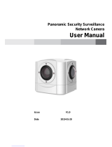
Geovision GV-VR360 User manual
- Category
- Security cameras
- Type
- User manual
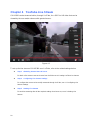
Geovision GV-VR360 is a virtual reality IP camera that will enable you to monitor your surroundings in great detail. It supports two-way audio, allowing you to communicate with people or pets in the vicinity of the camera. Thanks to the infrared night vision you can get footage even in poorly lit environments. Additionally, the camera can be set up to send alerts via email if any suspicious motion is detected. Using the dedicated app, you can remotely access the camera’s live feed and recordings from your mobile device.
Geovision GV-VR360 is a virtual reality IP camera that will enable you to monitor your surroundings in great detail. It supports two-way audio, allowing you to communicate with people or pets in the vicinity of the camera. Thanks to the infrared night vision you can get footage even in poorly lit environments. Additionally, the camera can be set up to send alerts via email if any suspicious motion is detected. Using the dedicated app, you can remotely access the camera’s live feed and recordings from your mobile device.


-
 1
1
-
 2
2
-
 3
3
-
 4
4
-
 5
5
-
 6
6
-
 7
7
-
 8
8
-
 9
9
-
 10
10
-
 11
11
-
 12
12
-
 13
13
-
 14
14
-
 15
15
-
 16
16
-
 17
17
-
 18
18
-
 19
19
-
 20
20
-
 21
21
-
 22
22
-
 23
23
-
 24
24
-
 25
25
-
 26
26
-
 27
27
-
 28
28
-
 29
29
-
 30
30
-
 31
31
-
 32
32
-
 33
33
-
 34
34
-
 35
35
-
 36
36
-
 37
37
-
 38
38
-
 39
39
-
 40
40
-
 41
41
-
 42
42
-
 43
43
-
 44
44
-
 45
45
-
 46
46
-
 47
47
-
 48
48
-
 49
49
-
 50
50
-
 51
51


Geovision GV-VR360 User manual
- Category
- Security cameras
- Type
- User manual
Geovision GV-VR360 is a virtual reality IP camera that will enable you to monitor your surroundings in great detail. It supports two-way audio, allowing you to communicate with people or pets in the vicinity of the camera. Thanks to the infrared night vision you can get footage even in poorly lit environments. Additionally, the camera can be set up to send alerts via email if any suspicious motion is detected. Using the dedicated app, you can remotely access the camera’s live feed and recordings from your mobile device.
Ask a question and I''ll find the answer in the document
Finding information in a document is now easier with AI
Related papers
-
Geovision GV-GVS2100 Quick start guide
-
-
-
-
-
-
-
-
-
Other documents
-
 Sunell SN-IPP5790DDN User manual
-
 Viewtech GV-1000 Easy Manual
-
Toshiba network camera User manual
-
 PhotoShip One VR360 CARBON Assembly And Setup Manual
-
Lumens VS-LC101Bundle Owner's manual
-
LILIN FD2452E Quick Installation Manual
-
ICP iCAM-MR6422X Quick Start
-
-
Sensoray 3011 User manual
-
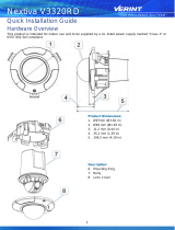 Nextiva V3320RD Quick Installation Manual


