Hotpoint HTDP120GD2WW Installation guide
- Category
- Electric laundry dryers
- Type
- Installation guide
This manual is also suitable for

,°sto,,ot,o°iGos yori@
Instructions
I
Questions? call800.GE.CARES (800.432.2737)or visitour Web siteat:GEAppliances.com
inCanada, call1.800.561.3344or visitwww.GEAppliances.ca I
BEFORE YOU BEGIN
Read these instructionscompletely and
carefully.
• IMPORTANT- savethese instructions
for local inspector's use.
• IMPORTANT = Observe all governing
codes and ordinances.
, Note to Installer- Be sure to leave these
instructions with the customer.
, Note to Customer - Keep these
instructions with your Owner's Manual for
future reference.
, Before the old dryer is removed from
service or discarded, remove the dryer
door.
, Inspect the dryer exhaust outlet and
straighten the outlet walls if they (]re bent.
Service information and the wiring
diagram (]re located in the control console.
Do not allow children on or in the appliance.
Close supervision of children is necessary
when the appliance is used near children.
Install the dryer where the temperature is
above 50°F for satisfactory operation of
the dryer control system.
Product failure due to improper instalk]tion
is not covered under the Warranty.
WARNING RISK OF FIRE
•Toreducethe riskof severe injury or death,follow oil installation instructions.
• Clothesdryer installation must be performed byo qualified instolle[
• Installthe clothes dryer according to these instructions and in accordance with local
codes.Inthe absence of local codes,installation must comply with Notional FuelGas
Code,ANSIZ223.1/NFPA54 or the Canadian Natural Gas and Propane Installation
Code,CSAB149.1.
• CaliforniaSofaDrinking Water ond ToxicEnforcementAct.
This oct requires the governor of California to publish a list of substances known to
the state to cause cancer, birth defects or other reproductive harm and requires
businesses to worn customers of potential exposure to such substances. Gas
appliances con cause minor exposure to four of these substances, namely benzene,
carbon monoxide, formaldehyde and soot, caused primarily by the incomplete
combustion of natural gas or LP fuels. Properly adJusted dryers will minimize
incomplete combustion. Exposureto these substances con be minimized further by
properly venting the dryer to the outdoors.
•Thisdryer must beexhausted to the outdoors.
• Useonly 4" rigid metal ducting for exhausting the clothes dryer to the outdoors.
• DO NOTinstall a clothes dryer with flexible plastic ducting materials, tfflexible metal
(semi-rigidor foil-type) duct isinstalled,it must beULlistedand installed in accordance
with the instructionsfound in "Connecting TheDryerToHouseVent"on page 6of this
manual. Flexibleventing materials ore known to collapse,be easilycrushed, and trap
lint.Theseconditions will obstruct dryer airflow and increase the risk of fire.
• Do not install or store this appliance in any location where it could be exposed to
water and or weathe[
• Save these instructions. (Installers: Be sure to leave these instructions with the
customer).
-- B
In the state of Massachusetts:
, Installation must be performed by a qualified or licensed contractor,
plumber, or gasfitter qualified or licensed by the state.
When using ball-type gas shut-offvalves, they shall be T-handle type.
A flexible gas connector, when used, must not exceed 3 feet.
TOOLS YOU WILL
NEED
1×2)
i0"ADJUSTABLEWRENCHES ____
8"PIPEWRENCH LEVEL
SLIPJOINTPLIERS FLATBLADESCREWDRIVER
.) MATERIALSYOU WILL NEED
4"DIA.METALDUCT P=====_
(RECOMMENDED)
4"DIAMMETALELBOW
4"DIA.FLEXIBLEMETAL(SEMI-RIGID)
ULLISTEDTRANSITIONDUCT
(IFNEEDED)
KITWXO8X10077(iNCLUDES2ELBOWS)
4"DIA.FLEXIBLEMETAL(FOILWPE)
ULLISTEDTRANSITIONDUCT
(IFNEEDED.)
PIPE
4"DUCTCLAMPS
OR
4"SPRINGCLAMPS
x2)
EXHAUSTHOOD COMPOUND
(x3
DUCTTAPE
FLEXIBLEGASLINECONNECTOR
0
SOAPSOLUTION
FORLEAKDETECTION
SAFETVGLASSES
GLOVES
IIIIIIIIIIIIIII
234D2217PO01 31-16735
III
i0-15 GE

Installation instructions
Minimum Clearance Other Than Alcove or Closet Installation
Minimum clear(]nce to combustible surf(]ces (]nd for (]iFopening (]re: 0 in, cle(]r(]nce both sides (]nd 1 in. re(]r.
Consider(]tion must be given to provide (]dequ(]te cle(]r(]nce for inst(]ll(]tion (]nd service.
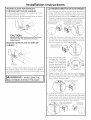
rl]PREPARING FOR INSTALLATION OF
NEW DRYER
TIP:Install your dryer before installing your washer.
This will allow better access when installing dryer
exhaust.
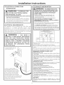
DISCONNECTING GAS
TURNGAS
SHUT-OFFVALVE IC_, DISCONNECTANDDISCARDOLD
TOTHEOFF _t_._J FLEXIBLEGASCONNECTORAND
POSiTiON
OLDTRANSITIONDUCTING
MATERIAL.REPLACEWITHNEW
CSA(AGA)APPROVEDFLEXIBLE
GASLINECONNECTORANDUL
APPROVEDTRANSITIONDUCT.
WARNING - NEVERREUSEOLD
FLE×II3LE CON NECTORS.
Theuseof old flexible connectors c(]n c(]use le(]ks(]nd
person(]l injury. AIw(]ys use new fexible connectors
when inst(]lling g(]s (]ppli(]nces.
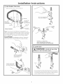
REMOVING LINT FROM WALL EXHAUST
OPENING
. Remove and discard existing plastic or metal foil
transition duct and replace with UL listed transition
duct.
WALL
INTERNALDUCT
CHECKTHATEXHAUST
OPENING HOODDAMPEROPENS
ANDCLOSESFREELY.
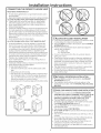
TILTTHE DRYERSIDEWAYS
AND REMOVETHE FOAM
SHIPPING PADS BY
PULLING ATTHE SIDES
AND BREAKING THEM
AWAY FROM THE DRYER
LEGS.BE SURETO
REMOVEALL OFTHE
FOAM PIECESAROUND
THE LEGS.
[][] GAS REQUIREMENTS
kWARNING
Installation must conform to local codes and
ordinances, or in their absence, the NATIONAL FUEL
GASCODE,ANSI Z223.
This gas dryer is equipped with a Valve & Burner
Assembly for use only with natural gas. Using
conversion kit WE25×0217, your local service
organization can convert this dryer for use with
propane {LPIgas. ALL CONVERSIONSHUST BE HADE
BY PROPERLYTRAINED AND QUALIFIED PERSONNEL
AND IN ACCORDANCE WITH LOCAL CODES AND
ORDINANCE REQUIREHENTS.
The dryer must be disconnected from the gas supply
piping system during any pressure testing of that
system at a test pressure in excess of O.5PSI(3.4 KPal.
The dryer must be isolated from the gas supply piping
system by closing the equipment shut-off valve
during any pressure testing of the gas supply piping
of test pressure equal to or less than 0.5 PSI(3.4 KPaI.
DRYERGASSUPPLYCONNECTION
A 2-5/8" " 3/8"NPTMALETHREADGASSUPPLY
NOTE:Addtoverticaldimension
thedistancebetweencabinet
bottomtofloor.
_AS SUPPLY
A 1/8-in.N(]tion(]l Pipe T(]per thre(]d plugged t(]pping,
(]ccessible for test g(]uge connection, must be inst(]lled
immedi(]tely upstre(]m of the g(]s supply connection to
the dryer. Cont(]ct your Ioc(]l g(]s utility should you h(]ve
questions on the inst(]ll(]tion of the plugged t(]pping.
Supply line isto be 1/2-in. rigid pipe (]nd equipped with
on (]ccessible shut-off within 6 ft. of, (]nd in the s(]me
room with the dryer.
Use pipe thre(]d se(]ler compound or Teflon t(]pe
(]ppropri(]te for natur(]l or LPg(]s.
You must use with this dryer (] flexible metal connector
listed connector ANSI Z21.24 / CSA6.10.The length of
the connect sh(]ll not exceed 3 ft.
Connect flexible met(]l connector to dryer (]ndg(]s supply.
Open shut-off v(]lve.
2
ADJUSTING FOR ELEVATION
, G(]sclothes dryers input r(]tings (]re b(]sed on se(] level
oper(]tion (]nd need not be (]djusted for oper(]tion (]t or
below 2000 ft. elev(]tion.
For oper(]tion (]t elev(]tions (]bove 2000 ft., input r(]tings
should be reduced (]t (] r(]te of 4 percent for e(]ch 1000
ft. (]bove se(] level.
, Inst(]ll(]tion must conform to Ioc(]lcodes(]ndordin(]nces or,
in their (]bsence,the NATIONALFUELGASCODE,ANSIZ223.

Installation
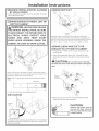
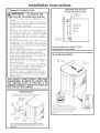
_] RECONNECTING GAS
Listed connector ANSI Z2!.24 / CSA 6.!0
1/8" NPT PIPE
NEW METAL PLUG FOR
GAS
FLEXIBLEGAS INLETPRESSURE
LINECONNECTOR
ADAPTER
ELBOW
3/8" NPT
SHUT-OFF
PIPESIZE
ITEMSNOT SUPPLIED _AT LEAST i/2"
Note: The connector and fittings ore designed for use
only on the original installution and ore not to be reused
for another uppliance or at another locution. Keep flare
end of adoptor free of grease, oil and thread sealant.
CAUTION: Use odoptersosshown,Connector
nutsmustnotbe connecteddirectlytopipethreods.
APPLYPIPECOMPOUND
TOTHEADAPTERAND
DRYERGASINLET,
TIGHTEN THE FLEXIBLE
GAS LINE USING TWO
ADJUSTABLE WRENCHES.
Instructions
APPLYPIPECOMPOUND
TOALL MALETHREADS.
TIGHTEN ALL CONNECTIONS
USINGTWO ADJUSTABLE WRENCHES.
DO NOT OVERTORQUE GAS CONNECTIONS!
[-_ LEAK TEST
,& WARNING: NEVER USE AN OPEN
FLAME TO TEST FOR GAS LEAKS.
\SVALVE.
._ckall connections for leoks with soapy solution or equivalent.
)ly soop solution. Leok test solution must not contoin ommonio
ch could cGuse damage to the brass fittings. If leoks (]re found,
_evGIve, retighten the joint, Gnd repeot the soop test.
3

Installation instructions
[ ELECTRICAL CONNECTION
INFORMATION
WARNING - TOREDUCETHE
RISK OF FIRE, ELECTRICAL SHOCK,
AND PERSONAL INJURY:
. DO NOT USEAN EXTENSIONCORDORAN ADAPTER
PLUGWiTH THiS APPLIANCE.
Dryer must be electrically grounded in accordance
with local codes and ordinances, or in the absence
of local codes, in accordance with the NATIONAL
ELECTRICALCODE,ANSI/NFPANO.70.
ELECTRICAL REQUIREMENTS
This appliance must be supplied with 120V, 60Hz, and
connected to a properly grounded branch circuit,
protected by a !5- or 20- amp circuit breaker or time-
delay fuse. If electrical supply provided does not meet the
above specifications, it is recommended that a licensed
electrician install an approved outlet.
WARNING - THISDRYERIS
EQUIPPED A THREE-PRONG (GROUNDING)
PLUG FOR YOUR PROTECTION AGAINST
SHOCK HAZARD AND SHOULD BE PLUGGED
DIRECTLY INTO A PROPERLY GROUNDED
THREE-PRONG RECEPTACLE. DO NOT CUT
OR REMOVE THE GROUNDING PRONG
FROM THIS PLUG.
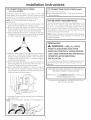
ENSUREPROPERGROUND
EXISTSBEFOREUSE.
IF LOCAL CODES PERMIT,
AN EXTERNAL GROUND WIRE
(NOT PROVIDED), WHICH MEETS
LOCAL CODES, MAY BE ADDED
BYATTACHING TO THE GREEN
GROUND SCREW ON THE REAR
OF THE DRYER, AND TO A GROUNDED
IVlETALCOLD WATER PIPE OR OTHER
ESTABLISHED GROUND.
EXHAUST INFORMATION
WARNING - IN CANADA AND IN THE
UNITED STATES,THE REQUIRED EXHAUST DUCT
DIAMETER IS4 IN (102ram). DO NOT USEDUCT
LONGER THAN SPECIFIED IN THE EXHAUST
LENGTH TABLE.
Usingexhaust longer than specifiedlength will:
. Increasethe dryingtimes and the energy cost.
. Reducethe dryer life.
, Accumulate lint, creating a potential fire hazard.
Thecorrect exhaust installation isYOUR
RESPONSiBiLITY.Problemsdue to incorrect installation
are not covered by the warranty.
Removeanddiscard existingplastic or metal foiltransition
duct and replacewith ULlisted transition duct.
TheMAXIMUMALLOWABLEduct length and number of
bends ofthe exhaustsystem depends upon the type of
duct, number of turns,the type of exhaust hood (wallcap),
and all conditions noted below.Themaximum duct length
for r_lid metal_own in the table below.
EXHAUST LENGTH
RECOMMENDED MAXIMUIV_ LENGTH
Exhaust Hood Types
Recommended Use only for short
run installations
NO of go° Rigid
Elbows kletaJ
9O Feet
6O Feet
A5 Feet 35 Feet
35 Feet 25 Feet
. Forevery extra 90° elbow, reducethe allowable vent system
length by 10 ft.
. Two 45° elbowswill be treated likeone 90° elbow.
. Forthe side exhaust installations,add one 90° elbow to the
chart.
. Thetotal vent system length includesall the straight portions
and elbows of the system(transition duct included).
EXHAUST SYSTEM CHECK LIST
HOOD ORWALL CAP
•Terminatein a mannerto preventbackdraftsor entryof birdsor
otherwildlife.
•Terminationshouldpresentminimal resistanceto the exhaustair
flowandshouldrequirelittleor nomaintenanceto preventclogging.
•Neverinstalla screeninor overtheexhaustduct.Thiscouldcause
lintbuildup.
•Wallcapsmustbeinstalledat least12in.abovegroundlevelorany
otherobstructionwiththeopeningpointeddown.
SEPARATIONOFTURNS
Forbestperformance,separateallturns byat least4ft. ofstraight
duct,includingdistancebetweenlastturnandexhausthood.
TURNSOTHERTHAN90°
•Oneturnof45°orlessmaybeignored.
•Two/450turnsshouldbetreatedasone900turn.
• Eachturnover450shouldbetreatedasone900turn.
SEALINGOFJOINTS
•Alljointsshouldbetighttoavoidleaks.Themaleendofeachsection
ofductmustpointawayfromthedryer.
•Donotassembletheductworkwithfastenersthat extendintothe
duct.Theywillserveasa collectionpointfor lint.
•Ductjoints can be madeair and moisture-tightbywrappingthe
overlappedjointswith ducttape.
•Horizontal runs should slope down toward the outdoors 1//4
inchperfoot.
INSULATION
Duct work that runs through an unheatedarea or is near air
conditioningshouldbe insulatedto reducecondensationand lint
build-up.
4

Installation instructions
[_ EXHAUST CONNECTION
WARNING -TOREDUCETHE
RISK OF FIRE OR PERSONAL INJURY:
, This clothes dryer must be exhausted to the
outdoors.
. We recommend that you install your dryer before
installing your washer. This will permit direct access
for easier exhaust connection.
Useonly 4"rigid metal ducting for the home exhaust
duct.
Use only 4" rigid metal or UL-listed flexible metal
(semi-rigid or foil-type) duct to connect the dryer
to the home exhaust duct. It must be installed
in accordance with the instructions found in
"Connecting The Dryer To House Vent" on page 6 of
this manual.
Do not terminate exhaust in a chimney, a wall,
a ceiling, gas vent, crawl space, attic, under on
enclosed floor, or in any other concealed space
of a building. The accumulated lint could create a
potential fire hazard.
Never terminate the exhaust into o common duct
with a kitchen exhaust system. A combination of
grease and lint creates a potential fire hazard.
Donot use duct longer than specified in the exhaust
length table. Longer ducts con accumulate lint,
creating a potential fire hazard.
Never install a screen in or over the exhaust duct.
This will cause lint to accumulate, creating a
potential fire hazard.
Do not assemble ductwork with any fasteners
that extend into the duct. These fasteners con
accumulate lint, creating a potential fire hazard.
Do not obstruct incoming or exhausted air.
Provide on access for inspection and cleaning of
the exhaust system, especially at turns and joints.
Exhaust system shall be inspected and cleaned at
least once year.
THIS DRYER COMES READY FOR REAR
EXHAUSTING, IF SPACE IS LIMITED, USE
THE INSTRUCTIONS IN SECTION 9 TO
EXHAUST DIRECTLY FROM THE SIDES OR
BOTTOM OF THE CABINET.
STANDARD REAR EXHAUST
(Vented at flaarlevel)
FORSTRAIGHTLINEINSTALLATION,CONNECTTHEDRYEREXHAUSTTO
THEEXTERNALEXHAUSTHOODUSINGDUCTTAPEORCLAIViR
CSA(AGA)APPROVED
NEWFLEXIBLEGAS
LINECONNECTOR
GAS
EXTERNAL
INLET
DUCT
PIPE
OPENING
DUCTTAPEOR
DUCTCLAMP
4" METALDUCT
(CUTTOPROPER
LENGTH) DUCTTAPEOR
DUCTCLAMP
NOTE:WE STRONGLYRECOMMENDSOLIDMETALEXHAUSTDUCTING.
HOWEVER,IF FLEXIBLEDUCTINGIS USEDITMUSTBEUL-LISTEDMETAL
NOTPLASTIC.
ELBOWHIGHLY
RECOMMENDED-
STANDARD REAR EXHAUST
(Vented above floorlevel)
ELBOWHIGHLY
_ RECOMMENDED
RECOMMENDED
CONFIGURATION
TOMINIMIZE
EXHAUST
BLOCKAGE.
NOTE: ELBOWS WILL PREVENT DUCT
KINKING AND COLLAPSING.
I-_ LEVELING DRYER
LEVEL
FRONT-TO-BACK.
--_._ LEVEL
SIDE-TO-SIDE.
4LEVELINGLEGS
STANDTHEDRYERUPRIGHTNEARTHE
FINALLOCATIONANDADJUSTTHE/4LEVELING
LEGSTOMATCHTHEHEIGHTOFYOURWASHER.
ADJUSTTHE2ANTI-TIPLEGSTOCONTACT
THEFLOOR.
2ANTI-TIPLEGS
5

Installation
CONNECTING THE DRYERTO HOUSE VENT
RIGID METALTRANSITION DUCT
• Forbestdrying performance,a rigid metaltransitionduct is
recommended.
• Rigidmetaltransitionsductsreducetheriskofcrushingandkinking.
UL-LISTEDFLEXIBLEMETAL(SEMI-RIGIDTRANSITIONDUCT
• tf rigid metalduct cannot be used,then UL-listedflexible
metal(semi-rigid)ducting canbeused(KitWX08X10077).
• Neverinstallflexiblemetal duct in walls,ceilings,floorsor
otherenclosedspaces.
• Totallengthofflexiblemetalductshouldnotexceed8feet(2.4m).
• Formany applications,installingelbowsat boththedryer
andthe wallishighlyrecommended(seeillustrationsbelow).
Elbowsallowthe dryerto sitcloseto thewallwithout kinking
andor crushingthetransition duct,maximizingdrying
performance.
• Avoidrestingthe ducton sharpobjects.
UL-LISTEDFLEXIBLEMETAL(FOIL-TYPE}TRANSITION DUCT
• tnspecialinstallations,it maybenecessaryto connectthe
dryertothe housevent usingaflexiblemetal(foiltype)duct.
A UL-listedflexiblemetal(foil-type)duct maybe usedONLY
ininstallationswhererigidmetalor flexiblemetal(semi-rigid)
ductingcannotbeusedANDwherea4" diametercanbe
maintainedthroughoutthe entirelengthofthetransitionduct.
• tnCanadaand the UnitedStates,onlytheflexiblemetal(foil-
type)ductsthat complywith the"Outlinefor ClothesDryer
TransitionDuctSubject2158A"shallbe used.
• Neverinstallflexiblemetal duct in walls,ceilings,floorsor
otherenclosedspaces.
• Totallengthofflexiblemetalductshouldnotexceed8feet(2.4m).
• Avoidrestingthe ducton sharpobjects.
• Forbestdrying performance:
1.Slideone endof theduct overthe clothesdryeroutlet
pipe.
2.Securethe duct with a clamp.
3.With the dryerin its permanentposition,extendthe duct
to its full length.Allow2"ofduct to overlaptheexhaust
pipe.Cutoff and removeexcessduct. Keeptheduct as
straightaspossiblefor maximumairflow.
4.Securethe duct to theexhaustpipewith the otherclamp.
ELBOWHIGHLY
RECOMMENDED
_WS HIGHLY
RECOMMENDE Lj/
Instructions
EXCESSIVE
EXHAUST
LENGTH
D]ALCOVE OR CLOSETINSTALLATION
• If yourdryerisapprovedfor installationinan alcoveor closet,
it will bestatedon a labelon thedryer back.
• ThedryerMUSTbe ventedto theoutdoors.Seethe EXHAUST
INFORMATIONsection.
• Minimumclearancebetweendryercabinet and adjacent
wallsor other surfacesis:
0in.eitherside
] in.front and rear
• Minimumverticalspacefrom floor to overheadcabinets,
ceiling,etc.is52 in.
• Closetdoorsmust beIouveredor otherwiseventilatedand
mustcontaina minimumof 60 sq.in.of openareaequally
distributed.Ifthe closetcontainsboth a washerand a dryer,
doorsmustcontain a minimumof 120sq.in,of openarea
equallydistributed.
• Theclosetshouldbeventedto the outdoorsto preventgas
pocketingincaseof a gasleakin the supplyline.
• Nootherfuel-burningapplianceshallbeinstalledinthe same
closetwith thedryer.
iTO]BATHROOM OR BEDROOM INSTALLATION
• ThedryerMUSTbe ventedtothe outdoors.SeeEXHAUST
INFORMATIONsection6.
• Theinstallationmustconformwith localcodesor,in the
absenceof localcodes,with the NATIONALFUELGASCODE,
ANSIZ223.
6
[n-IMOBILE OR MANUFACTUREDHOME INSTALLATION
• Installationmustconform tothe MANUFACTUREDHOME
CONSTRUCTION& SAFETYSTANDARD,TITLE24,PART32-80
or,whensuchstandard isnotapplicable,withAMERICAN
NATIONALSTANDARDFORMOBILEHOME,NO.501B.
• ThedryerMUSTbe ventedto theoutdoorswith the
termination securelyfastenedto the mobilehomestructure.
(SeeEXHAUSTINFORMATIONsection6.)
• Thevent MUSTNOTbeterminated beneatha mobileor
manufactured home.
• Thevent duct material MUSTBEMETAL.
• KIT14-D346-33MUSTbeusedto attachthe dryersecurelyto
the structure.
• Thevent MUSTNOTbeconnectedto anyother duct,vent,or
chimney.
• Donot usesheetmetal screwsor other refasteningdevices
which extendintothe interiorof theexhaustvent.
• Providean openingwith a freeareaof at least25sq.in.or
introductionof outsideair intothe dryerroom.
• Stackingofa gasdryerisnot permittedin a mobilehomeor
manufactured home.

Installation
[]GARAGE INSTALLATION {IF ALLOWED
BY LOCAL CODES}
, Dryers installed in garages must be elevated 18 inches
(46cm) above the floor.
[13]DRYER EXHAUST TO RIGHT, LEFT OR
BOTTOM CABINET
WARNING-BEFOREPERFORMING
THIS EXHAUST INSTALLATION, BE SURE
TO DISCONNECT THE DRYER FROM ITS
ELECTRICAL SUPPLY. PROTECT YOUR
HANDS AND ARMS FROM SHARP
EDGES WHEN WORKING INSIDE THE
CABINET. BE SURE TO WEAR GLOVES.
REMOVE
SCREW
ANDSAVE.
REMOVE//_
DESIRED
KNOCKOUT
(ONEONLY).
Detach and remove the bottom, right or left sideknockout
as desired.Removethe screw insidethe drger exhaust duct
and save.Pullthe duct out ofthe dryer.
Note: Only 4" round rigid metal ducting allowed inside
dryer.
FIXINGHOLE,
J_ 9"
Cut the duct as shown and keep portion A.
TAB LOCATION
BENDTAB
UP45o
Through the rear opening, locate the tab in the middle of
the appliance base. Lift the tab to about 450 using a flat
blade screwdriver.
Instructions
ADDING NEW DUCT
FIXING
HOLE
PORTION"A"
LEFTSIDE
EXHAUST
Reconnectthe cut portion (A)of the duct to the blower
housing. Makesurethat the shortened duct isaligned with
the tab inthe base.Usethe screw saved previouslgto secure
the duct in placethrough the tab on the appliance base.
ADDING ELBOW AND DUCT FOR
EXHAUST TO LEFT SIDE OF CABINET
. Preassemble 4" elbow with 4" duct. Wrap duct tape
around joint.
, Insert duct assembly, elbow first, through the side
opening and connect the elbow to the dryer internal
duct.
CAUTION: Be sure not to pullor damage
the electrical wires inside the dryer when inserting the
duct.
BEADDEDTO _-_z I F'_7[
LEFTOR RIGHTSIDE _
IN____ DUCT
TAPE
. Apply duct tape as shown on the joint between the
dryer internal duct and the elbow.
DUCT
,TAPE
CAUTION:
Internal duct joints must be
secured with tape, otherwise
_ they may separate and cause
U a safety hazard.
7

Installation
ADDING ELBOW FOR EXHAUST
THROUGH BOTTOM OF CABINET
, Insert the elbow through the rear opening and connect
it to the dryer internal duct.
. Apply duct tape on the joint between the dryer internal
duct and elbow, as shown on page 7.
CAUTION:
Internal duct joints must be secured with tape,
otherwise they may separate and cause a
safety hazard.
ADDING COVER PLATE TO REAR OF
CABINET
(KITWEII454)
Connect standard metal elbows and ducts to complete
the exhaust system. Cover back opening with a plate (Kit
WE1M454) available from your local service provider. Place
dryer in final location.
WARNING - NEVERLEAVETHE
BACK OPENING WITHOUT THE PLATE.
Instructions
F_CHANGING DIRECTIONOFDOOROPENING
1.Open the door and remove the filler plugs opposite the
hinges. With the door completely open, remove the
bottom screws from each hinge on the dryer face. Insert
these screws about half way into the TOPholes, for each
hinge on the opposite side (where you removed the filler
plugs). Apply firm pressure to get the screws started.
REMOVE 4 PLUGS AND KEEP
FOR INSERTION INTO
THE OPPOSITE SIDE
REMOVE BOTTOM SCREW FROM EACH HINGE
AND INSTALL HALF WAY INTO EACH TOP OF
OPPOSITE HINGE HOLES ._f"_-_*-_
!,i
t
2.Loosen the top screws from each hinge on the dryer
face halfway. With one hand holding the top of the door
and the other hand holding the bottom, remove the
door from the dryer by lifting it UPand OFF.
LOOSEN EACH TOP HINGE .j_'_,. _ _-__
REE oTJW ?o LIFT/ \
3.Removethe blind plate from
the hinge side of the dryer
by removing its two screws. _:,_
Remove the strike plate :;
from theopposite sideof the sTRiK_ /BLIND
dryer by removing its two PLATE:
screws. Reinstallthe plates, FRONTPANEL
on the opposite sides,using
two screws in each plate.
4.Rotate the door 180°. Insert the door on the opposite
side of the opening by moving the door ON and DOWN
until the top hinge and the bottom hinge are resting on
the top screws inserted in step 1.
o
ROTATE DOOR 180 AND HANG
IT ON TOP HINGE SCREWS
5.Remove the remaining screws from the side of the
opening from which the door was removed. With these
screws secure each hinge at the bottom. Tighten the
two top screws on each hinge. Reinsertthe plastic plugs
on the side from which the door was removed.
INSTALL AND TIGHTEN BO]q-OM
"_X SCREWS AND TIGHTEN TOP
INSERT PLUGS
INTO HOLES ON
OPPOSITE SIDE
8

Installation Instructions
[] CONNECTING INLET HOSES
fan some models)
To produce steam, the dryer must connect to the cold
water supply. Since the washer must also connect to the
cold water, a "Y" connector is inserted to allow both inlet
hoses to make that connection at the same time.
NOTE:Usethe new inlet hoses provided; never
use old hoses.
1.Turn the cold water faucet off. Removethe washer inlet
hose from the washer fill valve connector (cold).
2. Ensurethe rubber fiat washer is in place and screw the
female coupling of the short hose onto the washer fill
valve connector. Tighten by hand until firmly seated.
3. Attach the female end of the "Y" connector to the mule
coupling of the short hose. Ensurethe rubber fiat washer
isin place. Tighten by hand until firmly seated.
4. Insert the filter screen in the coupling of the washer's
inlet hose. If a rubber fiat washer is already in place
remove it before installing the filter screen. Attach this
coupling to one male end of the "Y" connector. Tighten
by hand until firmly seated.
5. Ensurethe rubber fiat washer is in place and attach the
dryer's long inlet hose to the other male end of the "Y"
connector. Tighten by hand until firmly seated.
6. Ensure the rubber fiat washer is in place and attach
the other end of the dryer's long inlet hose to the fill
valve connector at the bottom of the dryer back panel.
Tighten by hand until firmly seated.
7. Using pliers, tighten all the couplings with an additional
two-thirds turn.
NOTE: Do not overtighten. Damage to the couplings may
result.
[] CONNECTING INLET HOSES Icont.)
8.Turn the water faucet on.
9. Check for leaks around the "Y" connector, faucet and
hose couplings.
WATER SUPPLY REQUIREMENTS
Hot and cold water faucets IvlUSTbe installed within 42 in.
(107 cm) of your washer's water inlet. The faucets MUST
be 3/4 in. (1.9 cm) garden hose-type so inlet hoses can
be connected. Water pressure MUSTbe between 10 and
120 pounds per square inch. Your water department can
advise you of your water pressure.
NOTE:Awater softener is recommended to reduce buildup
of scale inside the steam generator if the home water
supply isvery hard.
_SERVICING
WARNING- LABEL ALL WIRES
PRIOR TO DISCONNECTION WHEN
SERVICING CONTROLS. WIRING ERRORS
CAN CAUSE IMPROPER AND DANGEROUS
OPERATION AFTER SERVICING/
INSTALLATION.
Forservicing phone numbers for replacement parts, and
other information, refer to Owner's Manual or visit our
Web site.
REGISTERYOUR NEW APPLIANCE TO RECEIVEANY
IMPORTANT PRODUCT NOTIFICATIONS.
Please go to www.GEAppliances.com or mail in your
Product Registration Card.
For questions on installation, call: 800.626.2000 (US)or
800-561-3344 (Canada).
9

Notes
10

Notes
11

Notes
12

,°sto,,ot,o°iGos yori@
Instructions
I
Questions? call800.GE.CARES (800.432.2737)or visitour Web siteat:GEAppliances.com
inCanada, call1.800.561.3344or visitwww.GEAppliances.ca I
BEFORE YOU BEGIN
Read these instructionscompletely and
carefully.
• IMPORTANT- savethese instructions
for local inspector's use.
• IMPORTANT = Observe all governing
codes and ordinances.
, Note to Installer- Be sure to leave these
instructions with the customer.
, Note to Customer - Keep these
instructions with your Owner's Manual for
future reference.
, Before the old dryer is removed from
service or discarded, remove the dryer
door.
, Inspect the dryer exhaust outlet and
straighten the outlet walls if they (]re bent.
Service information and the wiring
diagram (]re located in the control console.
Do not allow children on or in the appliance.
Close supervision of children is necessary
when the appliance is used near children.
Install the dryer where the temperature is
above 50°F for satisfactory operation of
the dryer control system.
Product failure due to improper instalk]tion
is not covered under the Warranty.
WARNING RISK OF FIRE
•Toreducethe risk of severe injury or death,follow oil installation instructions.
• Clothesdryer installation must be performed byo qualified instolle[
• Installthe clothes dryer according to these instructions and in accordance with local
codes.Inthe absence of local codes,installation must comply with Notional FuelGas
Code,ANSIZ223.1/NFPA54 or the Canadian Natural Gas and Propane Installation
Code,CSAB149.1.
• CaliforniaSofaDrinking Water ond ToxicEnforcementAct.
This oct requires the governor of California to publish a list of substances known to
the state to cause cancer, birth defects or other reproductive harm and requires
businesses to worn customers of potential exposure to such substances. Gas
appliances con cause minor exposure to four of these substances, namely benzene,
carbon monoxide, formaldehyde and soot, caused primarily by the incomplete
combustion of natural gas or LP fuels. Properly adJusted dryers will minimize
incomplete combustion. Exposureto these substances con be minimized further by
properly venting the dryer to the outdoors.
•Thisdryer must beexhausted to the outdoors.
• Useonly 4" rigid metal ducting for exhausting the clothes dryer to the outdoors.
• DO NOTinstall a clothes dryer with flexible plastic ducting materials, tfflexible metal
(semi-rigidor foil-type) duct isinstalled,it must beULlistedand installed in accordance
with the instructionsfound in "Connecting TheDryerToHouseVent"on page 6of this
manual. Flexibleventing materials ore known to collapse,be easilycrushed, and trap
lint.Theseconditions will obstruct dryer airflow and increase the risk of fire.
• Do not install or store this appliance in any location where it could be exposed to
water and or weathe[
• Save these instructions. (Installers: Be sure to leave these instructions with the
customer).
-- B
In the state of Massachusetts:
, Installation must be performed by a qualified or licensed contractor,
plumber, or gasfitter qualified or licensed by the state.
When using ball-type gas shut-offvalves, they shall be T-handle type.
A flexible gas connector, when used, must not exceed 3 feet.
TOOLS YOU WILL
NEED
1×2)
i0"ADJUSTABLEWRENCHES ____
8"PIPEWRENCH LEVEL
SLIPJOINTPLIERS FLATBLADESCREWDRIVER
.) MATERIALSYOU WILL NEED
4"DIA.METALDUCT P=====_
(RECOMMENDED)
4"DIAMMETALELBOW
4"DIA.FLEXIBLEMETAL(SEMI-RIGID)
ULLISTEDTRANSITIONDUCT
(IFNEEDED)
KITWXO8X10077(iNCLUDES2ELBOWS)
4"DIA.FLEXIBLEMETAL(FOILWPE)
ULLISTEDTRANSITIONDUCT
(IFNEEDED.)
PIPE
4"DUCTCLAMPS
OR
4"SPRINGCLAMPS
x2)
EXHAUSTHOOD COMPOUND
(x3
DUCTTAPE
FLEXIBLEGASLINECONNECTOR
0
SOAPSOLUTION
FORLEAKDETECTION
SAFETVGLASSES
GLOVES
IIIIIIIIIIIIIII
234D2217PO01 31-16735
III
i0-15 GE

Installation instructions
Minimum Clearance Other Than Alcove or Closet Installation
Minimum clear(]nce to combustible surf(]ces (]nd for (]iFopening (]re: 0 in, cle(]r(]nce both sides (]nd 1 in. re(]r.
Consider(]tion must be given to provide (]dequ(]te cle(]r(]nce for inst(]ll(]tion (]nd service.
rl]PREPARING FOR INSTALLATION OF
NEW DRYER
TIP:Install your dryer before installing your washer.
This will allow better access when installing dryer
exhaust.
DISCONNECTING GAS
TURNGAS
SHUT-OFFVALVE IC_, DISCONNECTANDDISCARDOLD
TOTHEOFF _t_._J FLEXIBLEGASCONNECTORAND
POSiTiON
OLDTRANSITIONDUCTING
MATERIAL.REPLACEWITHNEW
CSA(AGA)APPROVEDFLEXIBLE
GASLINECONNECTORANDUL
APPROVEDTRANSITIONDUCT.
WARNING - NEVERREUSEOLD
FLE×II3LE CON NECTORS.
Theuseof old flexible connectors c(]n c(]use le(]ks(]nd
person(]l injury. AIw(]ys use new fexible connectors
when inst(]lling g(]s (]ppli(]nces.
REMOVING LINT FROM WALL EXHAUST
OPENING
. Remove and discard existing plastic or metal foil
transition duct and replace with UL listed transition
duct.
WALL
INTERNALDUCT
CHECKTHATEXHAUST
OPENING HOODDAMPEROPENS
ANDCLOSESFREELY.
TILTTHE DRYERSIDEWAYS
AND REMOVETHE FOAM
SHIPPING PADS BY
PULLING ATTHE SIDES
AND BREAKING THEM
AWAY FROM THE DRYER
LEGS.BE SURETO
REMOVEALL OFTHE
FOAM PIECESAROUND
THE LEGS.
[][] GAS REQUIREMENTS
kWARNING
Installation must conform to local codes and
ordinances, or in their absence, the NATIONAL FUEL
GASCODE,ANSI Z223.
This gas dryer is equipped with a Valve & Burner
Assembly for use only with natural gas. Using
conversion kit WE25×0217, your local service
organization can convert this dryer for use with
propane {LPIgas. ALL CONVERSIONSHUST BE HADE
BY PROPERLYTRAINED AND QUALIFIED PERSONNEL
AND IN ACCORDANCE WITH LOCAL CODES AND
ORDINANCE REQUIREHENTS.
The dryer must be disconnected from the gas supply
piping system during any pressure testing of that
system at a test pressure in excess of O.5PSI(3.4 KPal.
The dryer must be isolated from the gas supply piping
system by closing the equipment shut-off valve
during any pressure testing of the gas supply piping
of test pressure equal to or less than 0.5 PSI(3.4 KPaI.
DRYERGASSUPPLYCONNECTION
A 2-5/8" " 3/8"NPTMALETHREADGASSUPPLY
NOTE:Addtoverticaldimension
thedistancebetweencabinet
bottomtofloor.
_AS SUPPLY
A 1/8-in.N(]tion(]l Pipe T(]per thre(]d plugged t(]pping,
(]ccessible for test g(]uge connection, must be inst(]lled
immedi(]tely upstre(]m of the g(]s supply connection to
the dryer. Cont(]ct your Ioc(]l g(]s utility should you h(]ve
questions on the inst(]ll(]tion of the plugged t(]pping.
Supply line isto be 1/2-in. rigid pipe (]nd equipped with
on (]ccessible shut-off within 6 ft. of, (]nd in the s(]me
room with the dryer.
Use pipe thre(]d se(]ler compound or Teflon t(]pe
(]ppropri(]te for natur(]l or LPg(]s.
You must use with this dryer (] flexible metal connector
listed connector ANSI Z21.24 / CSA6.10.The length of
the connect sh(]ll not exceed 3 ft.
Connect flexible met(]l connector to dryer (]ndg(]s supply.
Open shut-off v(]lve.
2
ADJUSTING FOR ELEVATION
, G(]sclothes dryers input r(]tings (]re b(]sed on se(] level
oper(]tion (]nd need not be (]djusted for oper(]tion (]t or
below 2000 ft. elev(]tion.
For oper(]tion (]t elev(]tions (]bove 2000 ft., input r(]tings
should be reduced (]t (] r(]te of 4 percent for e(]ch 1000
ft. (]bove se(] level.
, Inst(]ll(]tion must conform to Ioc(]lcodes(]ndordin(]nces or,
in their (]bsence,the NATIONALFUELGASCODE,ANSIZ223.

Installation
_] RECONNECTING GAS
Listed connector ANSI Z2!.24 / CSA 6.!0
1/8" NPT PIPE
NEW METAL PLUG FOR
GAS
FLEXIBLEGAS INLETPRESSURE
LINECONNECTOR
ADAPTER
ELBOW
3/8" NPT
SHUT-OFF
PIPESIZE
ITEMSNOT SUPPLIED _AT LEAST i/2"
Note: The connector and fittings ore designed for use
only on the original installution and ore not to be reused
for another uppliance or at another locution. Keep flare
end of adoptor free of grease, oil and thread sealant.
CAUTION: Use odoptersosshown,Connector
nutsmustnotbe connecteddirectlytopipethreods.
APPLYPIPECOMPOUND
TOTHEADAPTERAND
DRYERGASINLET,
TIGHTEN THE FLEXIBLE
GAS LINE USING TWO
ADJUSTABLE WRENCHES.
Instructions
APPLYPIPECOMPOUND
TOALL MALETHREADS.
TIGHTEN ALL CONNECTIONS
USINGTWO ADJUSTABLE WRENCHES.
DO NOT OVERTORQUE GAS CONNECTIONS!
[-_ LEAK TEST
,& WARNING: NEVER USE AN OPEN
FLAME TO TEST FOR GAS LEAKS.
\SVALVE.
._ckall connections for leoks with soapy solution or equivalent.
)ly soop solution. Leok test solution must not contoin ommonio
ch could cGuse damage to the brass fittings. If leoks (]re found,
_evGIve, retighten the joint, Gnd repeot the soop test.
3

Installation instructions
[ ELECTRICAL CONNECTION
INFORMATION
WARNING - TOREDUCETHE
RISK OF FIRE, ELECTRICAL SHOCK,
AND PERSONAL INJURY:
. DO NOT USEAN EXTENSIONCORDORAN ADAPTER
PLUGWiTH THiS APPLIANCE.
Dryer must be electrically grounded in accordance
with local codes and ordinances, or in the absence
of local codes, in accordance with the NATIONAL
ELECTRICALCODE,ANSI/NFPANO.70.
ELECTRICAL REQUIREMENTS
This appliance must be supplied with 120V, 60Hz, and
connected to a properly grounded branch circuit,
protected by a !5- or 20- amp circuit breaker or time-
delay fuse. If electrical supply provided does not meet the
above specifications, it is recommended that a licensed
electrician install an approved outlet.
WARNING - THISDRYERIS
EQUIPPED A THREE-PRONG (GROUNDING)
PLUG FOR YOUR PROTECTION AGAINST
SHOCK HAZARD AND SHOULD BE PLUGGED
DIRECTLY INTO A PROPERLY GROUNDED
THREE-PRONG RECEPTACLE. DO NOT CUT
OR REMOVE THE GROUNDING PRONG
FROM THIS PLUG.
ENSUREPROPERGROUND
EXISTSBEFOREUSE.
IF LOCAL CODES PERMIT,
AN EXTERNAL GROUND WIRE
(NOT PROVIDED), WHICH MEETS
LOCAL CODES, MAY BE ADDED
BYATTACHING TO THE GREEN
GROUND SCREW ON THE REAR
OF THE DRYER, AND TO A GROUNDED
IVlETALCOLD WATER PIPE OR OTHER
ESTABLISHED GROUND.
EXHAUST INFORMATION
WARNING - IN CANADA AND IN THE
UNITED STATES,THE REQUIRED EXHAUST DUCT
DIAMETER IS4 IN (102ram). DO NOT USEDUCT
LONGER THAN SPECIFIED IN THE EXHAUST
LENGTH TABLE.
Usingexhaust longer than specifiedlength will:
. Increasethe dryingtimes and the energy cost.
. Reducethe dryer life.
, Accumulate lint, creating a potential fire hazard.
Thecorrect exhaust installation isYOUR
RESPONSiBiLITY.Problemsdue to incorrect installation
are not covered by the warranty.
Removeanddiscard existingplastic or metal foiltransition
duct and replacewith ULlisted transition duct.
TheMAXIMUMALLOWABLEduct length and number of
bends ofthe exhaustsystem depends upon the type of
duct, number of turns,the type of exhaust hood (wallcap),
and all conditions noted below.Themaximum duct length
for r_lid metal_own in the table below.
EXHAUST LENGTH
RECOMMENDED MAXIMUIV_ LENGTH
Exhaust Hood Types
Recommended Use only for short
run installations
NO of go° Rigid
Elbows kletaJ
9O Feet
6O Feet
A5 Feet 35 Feet
35 Feet 25 Feet
. Forevery extra 90° elbow, reducethe allowable vent system
length by 10 ft.
. Two 45° elbowswill be treated likeone 90° elbow.
. Forthe side exhaust installations,add one 90° elbow to the
chart.
. Thetotal vent system length includesall the straight portions
and elbows of the system(transition duct included).
EXHAUST SYSTEM CHECK LIST
HOOD ORWALL CAP
•Terminatein a mannerto preventbackdraftsor entryof birdsor
otherwildlife.
•Terminationshouldpresentminimal resistanceto the exhaustair
flowandshouldrequirelittleor nomaintenanceto preventclogging.
•Neverinstalla screeninor overtheexhaustduct.Thiscouldcause
lintbuildup.
•Wallcapsmustbeinstalledat least12in.abovegroundlevelorany
otherobstructionwiththeopeningpointeddown.
SEPARATIONOFTURNS
Forbestperformance,separateallturns byat least4ft. ofstraight
duct,includingdistancebetweenlastturnandexhausthood.
TURNSOTHERTHAN90°
•Oneturnof45°orlessmaybeignored.
•Two/450turnsshouldbetreatedasone900turn.
• Eachturnover450shouldbetreatedasone900turn.
SEALINGOFJOINTS
•Alljointsshouldbetighttoavoidleaks.Themaleendofeachsection
ofductmustpointawayfromthedryer.
•Donotassembletheductworkwithfastenersthat extendintothe
duct.Theywillserveasa collectionpointfor lint.
•Ductjoints can be madeair and moisture-tightbywrappingthe
overlappedjointswith ducttape.
•Horizontal runs should slope down toward the outdoors 1//4
inchperfoot.
INSULATION
Duct work that runs through an unheatedarea or is near air
conditioningshouldbe insulatedto reducecondensationand lint
build-up.
4

Installation instructions
[_ EXHAUST CONNECTION
WARNING -TOREDUCETHE
RISK OF FIRE OR PERSONAL INJURY:
, This clothes dryer must be exhausted to the
outdoors.
. We recommend that you install your dryer before
installing your washer. This will permit direct access
for easier exhaust connection.
Useonly 4"rigid metal ducting for the home exhaust
duct.
Use only 4" rigid metal or UL-listed flexible metal
(semi-rigid or foil-type) duct to connect the dryer
to the home exhaust duct. It must be installed
in accordance with the instructions found in
"Connecting The Dryer To House Vent" on page 6 of
this manual.
Do not terminate exhaust in a chimney, a wall,
a ceiling, gas vent, crawl space, attic, under on
enclosed floor, or in any other concealed space
of a building. The accumulated lint could create a
potential fire hazard.
Never terminate the exhaust into o common duct
with a kitchen exhaust system. A combination of
grease and lint creates a potential fire hazard.
Donot use duct longer than specified in the exhaust
length table. Longer ducts con accumulate lint,
creating a potential fire hazard.
Never install a screen in or over the exhaust duct.
This will cause lint to accumulate, creating a
potential fire hazard.
Do not assemble ductwork with any fasteners
that extend into the duct. These fasteners con
accumulate lint, creating a potential fire hazard.
Do not obstruct incoming or exhausted air.
Provide on access for inspection and cleaning of
the exhaust system, especially at turns and joints.
Exhaust system shall be inspected and cleaned at
least once year.
THIS DRYER COMES READY FOR REAR
EXHAUSTING, IF SPACE IS LIMITED, USE
THE INSTRUCTIONS IN SECTION 9 TO
EXHAUST DIRECTLY FROM THE SIDES OR
BOTTOM OF THE CABINET.
STANDARD REAR EXHAUST
(Vented at flaarlevel)
FORSTRAIGHTLINEINSTALLATION,CONNECTTHEDRYEREXHAUSTTO
THEEXTERNALEXHAUSTHOODUSINGDUCTTAPEORCLAIViR
CSA(AGA)APPROVED
NEWFLEXIBLEGAS
LINECONNECTOR
GAS
EXTERNAL
INLET
DUCT
PIPE
OPENING
DUCTTAPEOR
DUCTCLAMP
4" METALDUCT
(CUTTOPROPER
LENGTH) DUCTTAPEOR
DUCTCLAMP
NOTE:WE STRONGLYRECOMMENDSOLIDMETALEXHAUSTDUCTING.
HOWEVER,IF FLEXIBLEDUCTINGIS USEDITMUSTBEUL-LISTEDMETAL
NOTPLASTIC.
ELBOWHIGHLY
RECOMMENDED-
STANDARD REAR EXHAUST
(Vented above floorlevel)
ELBOWHIGHLY
_ RECOMMENDED
RECOMMENDED
CONFIGURATION
TOMINIMIZE
EXHAUST
BLOCKAGE.
NOTE: ELBOWS WILL PREVENT DUCT
KINKING AND COLLAPSING.
I-_ LEVELING DRYER
LEVEL
FRONT-TO-BACK.
--_._ LEVEL
SIDE-TO-SIDE.
4LEVELINGLEGS
STANDTHEDRYERUPRIGHTNEARTHE
FINALLOCATIONANDADJUSTTHE/4LEVELING
LEGSTOMATCHTHEHEIGHTOFYOURWASHER.
ADJUSTTHE2ANTI-TIPLEGSTOCONTACT
THEFLOOR.
2ANTI-TIPLEGS
5

Installation
CONNECTING THE DRYERTO HOUSE VENT
RIGID METALTRANSITION DUCT
• Forbestdrying performance,a rigid metaltransitionduct is
recommended.
• Rigidmetaltransitionsductsreducetheriskofcrushingandkinking.
UL-LISTEDFLEXIBLEMETAL(SEMI-RIGIDTRANSITIONDUCT
• tf rigid metalduct cannot be used,then UL-listedflexible
metal(semi-rigid)ducting canbeused(KitWX08X10077).
• Neverinstallflexiblemetal duct in walls,ceilings,floorsor
otherenclosedspaces.
• Totallengthofflexiblemetalductshouldnotexceed8feet(2.4m).
• Formany applications,installingelbowsat boththedryer
andthe wallishighlyrecommended(seeillustrationsbelow).
Elbowsallowthe dryerto sitcloseto thewallwithout kinking
andor crushingthetransition duct,maximizingdrying
performance.
• Avoidrestingthe ducton sharpobjects.
UL-LISTEDFLEXIBLEMETAL(FOIL-TYPE}TRANSITION DUCT
• tnspecialinstallations,it maybenecessaryto connectthe
dryertothe housevent usingaflexiblemetal(foiltype)duct.
A UL-listedflexiblemetal(foil-type)duct maybe usedONLY
ininstallationswhererigidmetalor flexiblemetal(semi-rigid)
ductingcannotbeusedANDwherea4" diametercanbe
maintainedthroughoutthe entirelengthofthetransitionduct.
• tnCanadaand the UnitedStates,onlytheflexiblemetal(foil-
type)ductsthat complywith the"Outlinefor ClothesDryer
TransitionDuctSubject2158A"shallbe used.
• Neverinstallflexiblemetal duct in walls,ceilings,floorsor
otherenclosedspaces.
• Totallengthofflexiblemetalductshouldnotexceed8feet(2.4m).
• Avoidrestingthe ducton sharpobjects.
• Forbestdrying performance:
1.Slideone endof theduct overthe clothesdryeroutlet
pipe.
2.Securethe duct with a clamp.
3.With the dryerin its permanentposition,extendthe duct
to its full length.Allow2"ofduct to overlaptheexhaust
pipe.Cutoff and removeexcessduct. Keeptheduct as
straightaspossiblefor maximumairflow.
4.Securethe duct to theexhaustpipewith the otherclamp.
ELBOWHIGHLY
RECOMMENDED
_WS HIGHLY
RECOMMENDE Lj/
Instructions
EXCESSIVE
EXHAUST
LENGTH
D]ALCOVE OR CLOSETINSTALLATION
• If yourdryerisapprovedfor installationinan alcoveor closet,
it will bestatedon a labelon thedryer back.
• ThedryerMUSTbe ventedto theoutdoors.Seethe EXHAUST
INFORMATIONsection.
• Minimumclearancebetweendryercabinet and adjacent
wallsor other surfacesis:
0in.eitherside
] in.front and rear
• Minimumverticalspacefrom floor to overheadcabinets,
ceiling,etc.is52 in.
• Closetdoorsmust beIouveredor otherwiseventilatedand
mustcontaina minimumof 60 sq.in.of openareaequally
distributed.Ifthe closetcontainsboth a washerand a dryer,
doorsmustcontain a minimumof 120sq.in,of openarea
equallydistributed.
• Theclosetshouldbeventedto the outdoorsto preventgas
pocketingincaseof a gasleakin the supplyline.
• Nootherfuel-burningapplianceshallbeinstalledinthe same
closetwith thedryer.
iTO]BATHROOM OR BEDROOM INSTALLATION
• ThedryerMUSTbe ventedtothe outdoors.SeeEXHAUST
INFORMATIONsection6.
• Theinstallationmustconformwith localcodesor,in the
absenceof localcodes,with the NATIONALFUELGASCODE,
ANSIZ223.
6
[n-IMOBILE OR MANUFACTUREDHOME INSTALLATION
• Installationmustconform tothe MANUFACTUREDHOME
CONSTRUCTION& SAFETYSTANDARD,TITLE24,PART32-80
or,whensuchstandard isnotapplicable,withAMERICAN
NATIONALSTANDARDFORMOBILEHOME,NO.501B.
• ThedryerMUSTbe ventedto theoutdoorswith the
termination securelyfastenedto the mobilehomestructure.
(SeeEXHAUSTINFORMATIONsection6.)
• Thevent MUSTNOTbeterminated beneatha mobileor
manufactured home.
• Thevent duct material MUSTBEMETAL.
• KIT14-D346-33MUSTbeusedto attachthe dryersecurelyto
the structure.
• Thevent MUSTNOTbeconnectedto anyother duct,vent,or
chimney.
• Donot usesheetmetal screwsor other refasteningdevices
which extendintothe interiorof theexhaustvent.
• Providean openingwith a freeareaof at least25sq.in.or
introductionof outsideair intothe dryerroom.
• Stackingofa gasdryerisnot permittedin a mobilehomeor
manufactured home.

Installation
[]GARAGE INSTALLATION {IF ALLOWED
BY LOCAL CODES}
, Dryers installed in garages must be elevated 18 inches
(46cm) above the floor.
[13]DRYER EXHAUST TO RIGHT, LEFT OR
BOTTOM CABINET
WARNING-BEFOREPERFORMING
THIS EXHAUST INSTALLATION, BE SURE
TO DISCONNECT THE DRYER FROM ITS
ELECTRICAL SUPPLY. PROTECT YOUR
HANDS AND ARMS FROM SHARP
EDGES WHEN WORKING INSIDE THE
CABINET. BE SURE TO WEAR GLOVES.
REMOVE
SCREW
ANDSAVE.
REMOVE//_
DESIRED
KNOCKOUT
(ONEONLY).
Detach and remove the bottom, right or left sideknockout
as desired.Removethe screw insidethe drger exhaust duct
and save.Pullthe duct out ofthe dryer.
Note: Only 4" round rigid metal ducting allowed inside
dryer.
FIXINGHOLE,
J_ 9"
Cut the duct as shown and keep portion A.
TAB LOCATION
BENDTAB
UP45o
Through the rear opening, locate the tab in the middle of
the appliance base. Lift the tab to about 450 using a flat
blade screwdriver.
Instructions
ADDING NEW DUCT
FIXING
HOLE
PORTION"A"
LEFTSIDE
EXHAUST
Reconnectthe cut portion (A)of the duct to the blower
housing. Makesurethat the shortened duct isaligned with
the tab inthe base.Usethe screw saved previouslgto secure
the duct in placethrough the tab on the appliance base.
ADDING ELBOW AND DUCT FOR
EXHAUST TO LEFT SIDE OF CABINET
. Preassemble 4" elbow with 4" duct. Wrap duct tape
around joint.
, Insert duct assembly, elbow first, through the side
opening and connect the elbow to the dryer internal
duct.
CAUTION: Be sure not to pullor damage
the electrical wires inside the dryer when inserting the
duct.
BEADDEDTO _-_z I F'_7[
LEFTOR RIGHTSIDE _
IN____ DUCT
TAPE
. Apply duct tape as shown on the joint between the
dryer internal duct and the elbow.
DUCT
,TAPE
CAUTION:
Internal duct joints must be
secured with tape, otherwise
_ they may separate and cause
U a safety hazard.
7

Installation
ADDING ELBOW FOR EXHAUST
THROUGH BOTTOM OF CABINET
, Insert the elbow through the rear opening and connect
it to the dryer internal duct.
. Apply duct tape on the joint between the dryer internal
duct and elbow, as shown on page 7.
CAUTION:
Internal duct joints must be secured with tape,
otherwise they may separate and cause a
safety hazard.
ADDING COVER PLATE TO REAR OF
CABINET
(KITWEII454)
Connect standard metal elbows and ducts to complete
the exhaust system. Cover back opening with a plate (Kit
WE1M454) available from your local service provider. Place
dryer in final location.
WARNING - NEVERLEAVETHE
BACK OPENING WITHOUT THE PLATE.
Instructions
F_CHANGING DIRECTIONOFDOOROPENING
1.Open the door and remove the filler plugs opposite the
hinges. With the door completely open, remove the
bottom screws from each hinge on the dryer face. Insert
these screws about half way into the TOPholes, for each
hinge on the opposite side (where you removed the filler
plugs). Apply firm pressure to get the screws started.
REMOVE 4 PLUGS AND KEEP
FOR INSERTION INTO
THE OPPOSITE SIDE
REMOVE BOTTOM SCREW FROM EACH HINGE
AND INSTALL HALF WAY INTO EACH TOP OF
OPPOSITE HINGE HOLES ._f"_-_*-_
!,i
t
2.Loosen the top screws from each hinge on the dryer
face halfway. With one hand holding the top of the door
and the other hand holding the bottom, remove the
door from the dryer by lifting it UPand OFF.
LOOSEN EACH TOP HINGE .j_'_,. _ _-__
REE oTJW ?o LIFT/ \
3.Removethe blind plate from
the hinge side of the dryer
by removing its two screws. _:,_
Remove the strike plate :;
from theopposite sideof the sTRiK_ /BLIND
dryer by removing its two PLATE:
screws. Reinstallthe plates, FRONTPANEL
on the opposite sides,using
two screws in each plate.
4.Rotate the door 180°. Insert the door on the opposite
side of the opening by moving the door ON and DOWN
until the top hinge and the bottom hinge are resting on
the top screws inserted in step 1.
o
ROTATE DOOR 180 AND HANG
IT ON TOP HINGE SCREWS
5.Remove the remaining screws from the side of the
opening from which the door was removed. With these
screws secure each hinge at the bottom. Tighten the
two top screws on each hinge. Reinsertthe plastic plugs
on the side from which the door was removed.
INSTALL AND TIGHTEN BO]q-OM
"_X SCREWS AND TIGHTEN TOP
INSERT PLUGS
INTO HOLES ON
OPPOSITE SIDE
8
Page is loading ...
Page is loading ...
Page is loading ...
Page is loading ...
-
 1
1
-
 2
2
-
 3
3
-
 4
4
-
 5
5
-
 6
6
-
 7
7
-
 8
8
-
 9
9
-
 10
10
-
 11
11
-
 12
12
-
 13
13
-
 14
14
-
 15
15
-
 16
16
-
 17
17
-
 18
18
-
 19
19
-
 20
20
-
 21
21
-
 22
22
-
 23
23
-
 24
24


Hotpoint HTDP120GD2WW Installation guide
- Category
- Electric laundry dryers
- Type
- Installation guide
- This manual is also suitable for
Ask a question and I''ll find the answer in the document
Finding information in a document is now easier with AI
Related papers
-
GE Profile DBSR453GAWW Installation guide
-
GE Profile NBXR333EGWW User manual
-
Hotpoint HTDX100EM4WW Installation guide
-
GE GHDP490EF2WW Installation guide
-
GE HTDX100GD5WW Installation guide
-
-
GE HTDX100EM3WW Installation guide
-
-
-
Hotpoint DVLR223GG1WW Installation guide
Other documents
-
-
Gibraltar Building Products DV4 Installation guide
-
Maytag MGD5801T User guide
-
Everbilt MFX48ULMKHD Operating instructions
-
-
Bosch WTMC3521UC/05 Owner's manual
-
Samsung DV45H6300EW/A3-00 Owner's manual
-
-
EASTMAN 98538 Installation guide
-
Samsung DV42H5000EW/A3-01 User manual