Friedrich PE07R3SA Owner's manual

Type
Owner's manual
WallMaster®PTAC
PackagedTerminalAirConditioners& Heat Pumps
Standard
RemoteThermostat
SeacoastProtected
Installation& OperationManual
920-087-02 (9-03)
920-087-02(9-03)
TableofContents
UnitComponents......................................................................................................................................................................................... 2
P-SeriesAnnouncement/ModelNumberCode............................................................................................................................................ 3
InstallationRecommendations.................................................................................................................................................................... 4
DrainKitInstallation ................................................................................................................................................................................ 5-6
Wall SleeveInstallation............................................................................................................................................................................ 7-8
DeepWallInstallation .................................................................................................................................................................................. 9
Standard GrilleInstallation ........................................................................................................................................................................ 10
InstallationChecklist................................................................................................................................................................................. 11
Electrical RatingTables.............................................................................................................................................................................. 11
ChassisInstallation............................................................................................................................................................................. 12-13
Standard UnitOperations.......................................................................................................................................................................... 14
TemperatureLimitingThermostat .............................................................................................................................................................. 14
HeatingControl(Heat Pumps& EmergencyHeat)..................................................................................................................................... 15
FanCycleSwitch....................................................................................................................................................................................... 15
FreshAirVentControl................................................................................................................................................................................ 15
AirDischargeGrille .................................................................................................................................................................................... 16
Start-up Checklist...................................................................................................................................................................................... 16
AppendixA: RemoteThermostatWiring............................................................................................................................................... 17-18
AppendixB: ElectricalWiringfor 265 V Models........................................................................................................................................ 19
RoutineMaintenance................................................................................................................................................................................ 20
BasicTroubleshootingTechniques............................................................................................................................................................. 21
Accessories......................................................................................................................................................................................... 22-23
Warranty................................................................................................................................................................................................... 24
TypicalUnit Components
Chassis
tcover
2
920-087-02 (9-03)
Announcing the FriedrichP-Series PackagedTerminalAir Conditioner.
A new approach to reliability and efficiency. A totally redesigned Friedrich PTAC.
Thank you for your decision to purchase the newly designed Friedrich Packaged Terminal Air Conditioner
(PTAC). We are confident that you will find this unit a quiet and efficient example of Friedrich reliability.
This Installation and Operation Manual has been designed to insure maximum satisfaction in the performance
of your unit. For years of trouble-free service, please follow the installation instructions closely. We cannot
overemphasize the importance of proper installation. We have added new information to the basic instructions
to help you achieve success.
Remember, proper installation is not difficult but it is essential.
Series
P= P series
System
X= Accessory
E= Coolingwith or
withoutelectric heat
H =HeatPumpwith
Auxiliary Heat
NominalCoolingCapac_y
07 = _000 Btuh
09 = 9,000 Btuh
12 = 12,000 Btuh
15 = 15,000 Btuh
ModelNumberCode
PH07K 3 S A 1
L
I EngineeringDigit I
I Designsedes I
Options
S = Standard
R = RemoteThermostat
C = SeacoastProtection
X = RemoteThermostatand
SeacoastProtection
NominalHeaterSize
(@230Vor 265V)
0 = NoHeater
2 = 2.5 KW
3 = 3.4 KW
5 = 5.0 KW
Voltage
K = 230/208V-1Ph.-60 Hz.
R = 265V-1Ph.-60 Hz.
Please read this manual thoroughly prior to equipment installation or operation. It isthe installer's responsibility
to properly apply and install the equipment. Installation must be in conformance with the NFPA 70-2002
National Electric Code or current edition and Universal Mechanical Code current edition and applicable local
or national codes.
3
920-087-02 (9-03)
PTACInstallation Recommendations
ForproperPTACunitperformanceandmaximumoperatinglifepleaserefertothe minimuminstallationclearancesbelow:
Figure I
PTAC units should be installed
no closer than 12"apart when
two units are side by side. If
three of more PTAC units are to
operate next to one another allow
a minimum of 36" between units.
Also, a vertical clearance of 60"
should be maintained between
units installed.
VIEW: OUTSIDE
BUILDING ELEVATION
60" VERTICAL M]MUMUM
BETWEEN PTACs
THREE OR MORE PTACs
#,DJACENT 36" MINIMUM
GROUND FLOOR PTACs
6" MINIMUM FROM GRADE
Figure 2
ForPTACsonthegroundfloororanytimeobstructionsarepresent,usethefollowingguidelines:
For minor obstructions
such as lamp poles or small
shrubbery a clearance of
12"from the outdoor louver
should be maintained.
For major obstructions such
as a solid fence, wall or
other heat rejecting device
like a condensing unit, a
minimum distance of 36"
should be kept.
TYP. BUILDING ( PLAN VIEW )
-- 36"_] [_ 36"--
PTAC 7 PTAC r
I I
I I
I I
I I
12" MINIMUM, MINOR
OBSTRUCTIONS _ 36"
36" MIMUMUM, MAJOR _
OBSTRUCTIONS _) ' ' ' FENCE OR WALL'
CONDENSING UNIT
PTAC
The above suggestions are for reference only and do notrepresent allpossible installations. Please contact the factory
for information regarding affects of other installation arrangements. By following these simple recommendations you
can be confident that your Friedrich PTAC will provide years of worry free operation.
4
920-087-02(9-03)
Installation Instructions PXDRIODrain Kit
NOTE: Determine whetherdrain willbe located within the wall, on the indoor side, or will drain to the exterior of the building. Follow
appropriate instructionsbelow depending on yourparticular type of installation.
Internal Drain (optional for new construction)
NOTE: Ifinstalling an internaldrain,you MUST install a drain kit on
the wall sleeve before the wall sleeve is installed.
1,
Refer to Figure 3 below and locate the drain within the
"Primary" area for best drainage. Maintain at least a 1/2"
clearance from the embossed area.
2.
Using the mounting plate with the 1/2" hole as a template,
mark and drill two, 3/16" mounting holes and a 1/2" drain
hole.
,
Removethe backingfrom thegasket andmount iton the flat
side of the mounting plate. (See Figure 4.) Insert the drain
tube through the hole in the gasket and mounting plate so
the tube flange will be against the wall sleeve.
4. Position the assembly beneaththe drilled holes and secure
itwith #10-24 x 1/2" machine screws and lock nuts provided.
Seal the tops of the screws with siliconecaulking.
5. Use 1/2" I.D.copper tube, PVCpipe, orvinylhose (obtained
locally) toconnect the internaldraintube tothe drain system
in the building.
6. Referring to Detail A on page 6, locate and assemble the
(2) two cover platesandgaskets over the drain holes atthe
rear ofthe wall sleeve.Attach them with the #10 sheet metal
screws provided. Makecertain that thefour overflow slotsat
the rear of the wall sleeve are not blocked (See drawing of
the back ofthe sleeveon page 6).
7. If a deep wall extension (PXWE) is used, after installing the
field supplied flashing, caulk as required. Be sure to caulk
around the flashing and thewall sleeve where the hole was
drilled for the drain tube.
Figure 3
DrainKitLocationandInstallation
Secondary area
Primary area _ no foam insulation --
If the drain must be located in the
secondary area, the foam insulation
must be cut away and removed to
allow access to the drain,
76 cm
Screw [_
Wail sleeve
Gasket t t
i
Mounting plateNut _ j _ I \\
)
5
920-087-02 (9-03)
ExtemalDrain(for newconstructionorunit replacement)
When usingan external drain system, the condensate is removed through eitherof two drain holes on the back of thewall sleeve. Select
the drain hole which bestmeets your drainagesituation and install the drain kit. Sealoff the other with a cover plate.
Drain Tube Installation
1. Peelthe backing tape off thegaskets and apply thesticky
side toone coverplateand one mounting plateas shown
in DetailsA and B,
2. Placethedrain tube throughthe gasketandthe mounting
plate with the flange toward the wall sleeve.
3. Attach the drain tube assembly to one of the two drain
holes at the rear of the wall sleeve. The large flange on
themountingplateispositionedatthe bottomofthesleeve
facing toward thesleeve, Detail B. When thedrain tube is
positioned at the desired angle,tighten the screws.
NOTE: Ifthewallsleeve hasnot been installed,the draintube must
be rotated to a horizontal position until after the sleeve
is installed. Tighten the mounting plate screws when the
tube is in the proper position. Make certain that the four
overflow slotsatthe rearofthewallsleeveare notblocked.
(See the drawing below.)
Cover Plate Installation
4. Mountthefoamgaskettothecoverplate. Usingtwo#10x
1/2"sheet metal screws (provided), attachthe cover plate
tothe remaining drainhole. Make certain the largeflange
on the plate ispositioned at the bottom of the sleeve.
5. Discardtheadditionalcoverplate,gasket,machinescrews,
and Iocknuts.
QUANTITY DESCRIPTION
2
1
1
3
4
2
2
COVER PLATES
MOUNTING PLATE
DRAIN TUBE
MOUNTING PLATE GASKETS
#10 X 1/2" MOUNTING SCREWS
10-24 X 1/2" MACH, SCREWS
LOCKNUTS
Figure 4
DrainKitInstallation
gasket
plate
DETAIL A
Foam gasket _ _/2"O.D.tube
Mounting plate #10 sheet metal screws
_DETAIL B
NOTES:
The large flange on the mounting plate ispositioned at the bottom of the sleeve facing toward the sleeve. The drain tube must be rotated to a horizontal
position to allow for the wall sleeve to be installed into the wall. Once the wall sleeve is installed, return the drain tube to a downward angle.
6
920-087-02(9-03)
WallSleeveInstallation Instructions(PXWS)
NOTE: Insurethat theunitisonlyinstalled inawall structurallyadequatetosupport the unitincludingthe sleeve,chassis and accessories.
Ifthe sleeve projects more than 8" intothe room, a subbase or other meansof support MUST be used. Please read these instructions
completely before attemptinginstallation.
Figure 5
TypicalWall Sleeve Installation
Lintel to support masonry walls .--_.b_//_
10"
(25.4 cm
Electrical receptacle -
Wall opening Wall sleeve
/
1 1_ _ /]
41._m) _\_'[_ -- -- Electrical receptacle
Insulation --
Smoothsideofscrew
slip facing into room
ForDeep Wall Installation See Section II
The following instructions apply ONLY to walls less than
13 1/4" indepth.
1. Frominsidethebuilding,positionthewall sleevein theopening
and push itthroughthe wall so itprotrudes atleast 1/4"on the
outside, note Figure 5.
2. Position thewall sleeve with a slight tilt towards the outside to
facilitate condensate drainage. Itshould be levelside-to-side
and the front should be 1/4 bubble higher than the back. DO
NOT allow any pitch toward the inside.
Electricalshockhazard.
Turnelectric power OFF at the fuse box or service panel
before making any electrical connections and ensure a
proper ground connectionis made before connectingline
voltage. Failureto do so can result in property damage,
personalinjuryand/ordeath.
920-087-02 (9-03)
Figure 6
Dimensions
A
S
_ ...........Wall
'_7€/////_ _ 6.4 cm
in.
13¾ _
Dimension*
A B
Allow Allow for floor finishing
for wall
finishing
(Minimum) Min. Max
No Accessories ¼" ¼"
(6.4 ram)* (6.4 mm) ---
With Subbase 1¾" 3½" 5"
(4.5 cm) (8.9cm) (12.7cm)
With Lateral Duct ¾" ¼"
(1.9 cm) (6.4 mm) ---
* If mere than one accessory [sto be used, use the maximum
dimension. Ifthe wail thickness is more than 13¾" (35cm) -
(A + ¼" [6.4 mm]), a sleeve extension must be used.
,
Drill two 3/16" holes through each side of the sleeve
approximately4" from top and4"from bottomofsleeve. Screw
four#10x 1"screws (included)or appropriatefastenersfor your
installation, through the holes inthe sides of the wall sleeve.
4. Apply sealant around thewall sleevewhere itprojectsthrough
the insideand outside wall surfaces. Apply the sealant tothe
screw headsor thetops of the fasteners used in Step #3.
NOTE: When sealing the sleeve on the outside of the building,
be careful NOT to let the sealant block the two condensate
drain holes or the four overflow slots at the bottom flange of
the sleeve.
5. Ifthe chassisandexteriorgrilleareto beinstanedlater,leavethe
weatherboard and centersupport in place, otherwise remove
and dispose of them.
6. Providea supportlintelifthewallsleeve isinstalledina concrete
or masonry wall. (See Figure 7.)
Rgure 7
Main studs
LintelInstallation Jack studs
Jack stud
Untel
Mounting screw holes
No holes in bottom of wall
sleeve unless drain kit is used
NOTE: Construct wall opening to comply with all applicable
building codes.
8
920-087-02 (9-03)
Section II - DeepWall Installation(PXWE)
If the wail is thicker than allowed in the notes in Figure 6, a sheet
metal wall sleeve extension and flashing MUST be used.
Installation Instructions for the PXWE - 4" Wall Sleeve
Extension
The following points MUST be considered when installing a wall
sleeve extension:
Provision must be made to direct excess condensate from
the back of the wall sleeve into the extension then outside
the building or to a drainage system.
2. Air baffles mustbe mountedto properlydirect airflow to and
from the condenser.
3. The wail sleeve extension design must allow for the proper
mounting of the grille.
4. Caulking isrequired atansiteswhere condensate or external
water could potentially infiltrate intothe building.
6. Condensate notches and overflow slots must be kept clear
ofsealant and gaskets so condensate canflow freely intothe
wall sleeve extension.
NOTE: Improperfabricationor installationofa wallsleeveextension
will impair PTAC performance.
Extension Installation
Secure thewall sleeveextensionto thewailsleeve beforeinstalling
it in the wall. Refer to Figure 8 for a guide for fabrication of a
condensate drip panel. The panel MUST extend the full depth of
the wail sleeve and the wail sleeve extension.
Payparticular carein sealingand caulkingthe panelwhere itmakes
contact with the wall sleeve (see Figure 8).After installationin the
wall, secure with fasteners through the sides. Use a good grade
of silicone sealant around the sleeve extension. Seal all exposed
screw heads. When the installation is complete, the outside grille
should be attached to the wall sleeve extension.
5. Fabricate and install metal flashing inwall to serve as a drip
panel. Refer to drawingfor more information.
Figure8
WallSleeveExtensionSealant Locations
®
IMPORTANT NOTE: The silicone bead MUST extend 3"
up the side of the two flanges to prevent condensate
from leaking.
Wall Sleeve
Outside Edge
Insulation
Wall Sleeve
Wall Sleeve Extension
Rear Flange Flange
| Wall SLoe %_j_) |
Silicone Bead T-_ "%'
Wall Sleeve
Extension
Sealant
I Drip Panel L
Sealant around perimeter
2 n
Sealant inside (4) bottom corners
Drip
Width of Wall Edge Notches (4)
Wall Sleeve Extension, 42" X 16" Frame, 20 gauge minimum, painted or aluminium
9
920-087-02(9-03)
Installation InstructionsModelPXGAStandardGrille
1. Remove the center support and weatherboardifstininstalled
in the sleeve.
2. Insert six plastic grommets into the grille openings from the
outside of the grille as shown in Figure 9.
3. Insert two #8 x 3/8" sheet metal screws (provided) in the top
two outside edge plasticgrommets, and tighten them halfway
intothe grommets.
4. CAUTION: Bodilyinjury can be caused by grillesfalling from
a building during installation. It is recommended that a safety
line be attached to the grille and an anchor point inside the
building durinq installation.
5. Graspthegrille bytheattached plastichandles. Positionitwith
thecondensate drain knockoutsfacing down. From insidethe
building, maneuver the grille through the wall sleeveand pull
toward you untilthe screw headsare inserted intothe keyhole
slots at the top of the wall sleeve. Tighten the two screws
completely.
6. Insert the remaining screws into the remaining holes and
tighten securely.
Figure 9
Quantity Description
1 Stamped Aluminum Grille
6 Plastic Grommets
6 #8 x 3/8"Sheet Metal Screws
Figure 9
StandardGrille
Waft sleeve
-- Weatherboard
-- Center support
Plastic handles
\
\
Plastic
grommets
10
920-087-02(9-03)
A. Installation Checklist
[]
[]
[]
[]
[]
Inspect all components and accessories for damage
before and after installation.
[] Installthe recommended Condensate Drain Kits for
complete condensate removal.
Removethe cardboard wall sleeve support and grille []
weatherboard.
Check for proper wall sleeve installation in accordance
with thewall sleeve installation instructions.
Check installationof the wall sleeve foam gasket.
Check for a subbase kitorother means of structural
support which is requiredfor ALL installationsprojecting
more than 8" into room.
Ensurethat the chassis is installed in a 16"high x42" wide
wall sleeve that isno deeper than
13 3/4". A baffle kit is required if the sleeve exceeds that
depth.
[] Ensurethat drapes, bed, bedspread, furniture, etc. DO
NOT block either returnor discharge air grilles.
[] Inspect the condenser air inletand outlet for any
obstructions (shrubbery,etc,)
B. ElectricalRatingTables
All230/208 voltunitsare equippedwithpowercords.SeeAppendixBonpage19 forwiringinstructionson 265V units.
NOTE: Use Copper Conductors ONLY. Wire sizesare per NEC,check local codes for overseas applications.
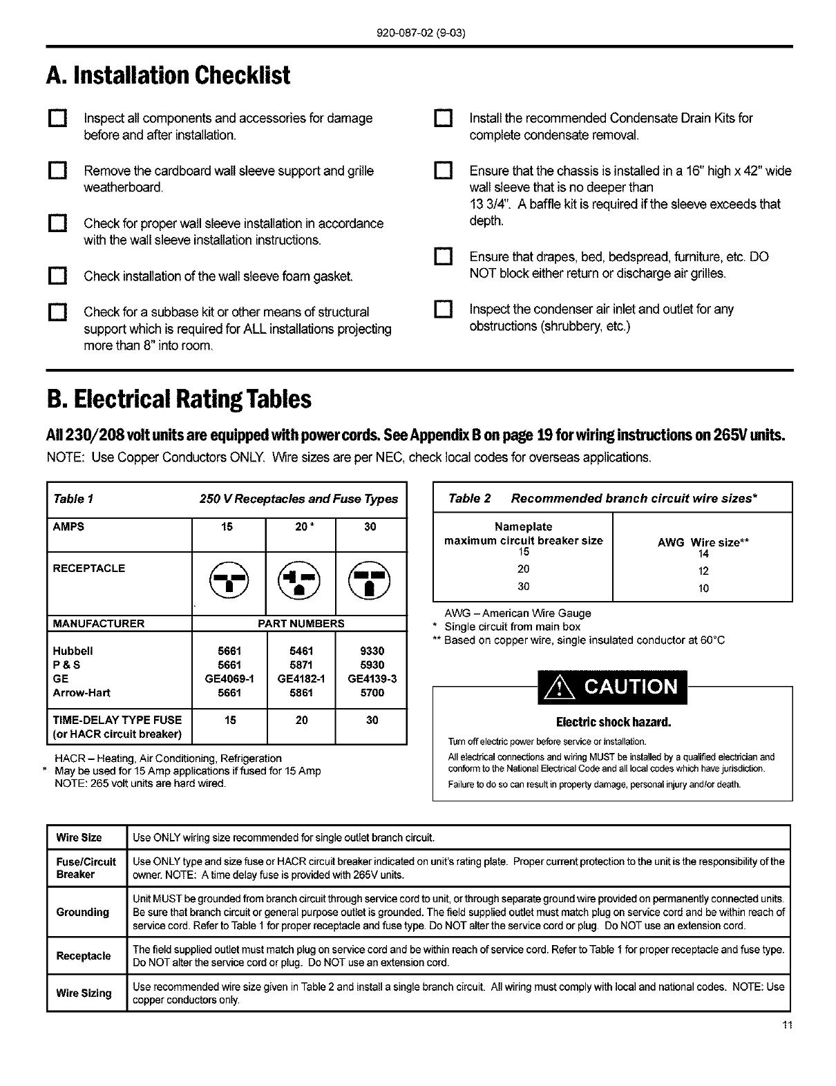
Table 1 250 V Receptacles and Fuse Types
AMPS 15 20 * 30
RECEPTACLE (_ (_ (_
MANUFACTURER PART NUMBERS
Hubbell 5661 5461 9330
P & S 5661 5871 5930
GE GE4069-1 GE4182-1 GE4139-3
Arrow-Hart 5661 5861 5700
TiME-DELAY TYPE FUSE 15 20 30
(or HACR circuit breaker)
HACR- Heating, Air Conditioning, Refrigeration
* May be used for 15Amp applications if fused for 15Amp
NOTE: 265 volt units are hard wired.
Table 2 Recommended branch circuit wire sizes*
Nameplate
maximum circuit breaker size AWG Wire size**
15 14
20 12
30 10
AWG -American Wire Gauge
* Single circuit from main box
** Based on copper wire, single insulated conductor at 60°C
Electric shock hazard.
Turnoffelectricpowerbeforeserviceorinstallation
A_IelectricalconnectionsandwiringMUSTbeinstaUedbya qualifiedelectricianand
confon'ntotheNationalElectricalCodeandalllocalcodeswhichhavejurisdiction
Failuretodosocanrescttinpropertydamage,personalinjuryand/ordeath.
Wire Size Use ONLY wiringsize recommendedfor single outlet branch circuit.
Fuse/Circuit Use ONLY type and size fuse or HACR circuit breaker indicated on unit's rating plate. Proper current protection to the unit is the responsibility of the
Breaker owner. NOTE: A time delay fuse is provided with 265V units.
Unit MUST begrounded from branch circuit through service cord to unit, or through separate ground wire providedon permanentlyconnected units.
Grounding Besure that branch circuit or general purpose outlet is grounded. The field supplied outlet must match plugon service cord and be within reach of
service cord. Refer to Table I for proper receptacle and fuse type. Do NOT alterthe service cord or plug. Do NOT use an extension cord.
The field supplied outlet must match plugon service cord and be within reach ofservice cord. Refer to Table 1for proper receptacle and fuse type.
Receptacle Do NOT alter the service cord or plug. Do NOT use an extension cord.
Use recommended wire size given in Table 2 and install a single branch circuit. All wiring must comply with local and national codes. NOTE: Use
Wire Sizing copper conductors only.
11
920-087-02(9-03)
Section III - ChassisInstallation
* Check to be surethe wall sleeve, extension (if used), grille, and drain kit are installed properly before
chassis installation
1. Remove the weatherboard and center support from
the sleeve (if still in place). Be sure an outdoor grille is
attached.
NOTE: Toavoid breaking the door or hinge pins, do not apply
excessive force when installing
_ Pins
Wall sleeve / Control
Door
-- Weatherboard
Center support
Front Panel
3. Remove the two chassis shipping brackets from the ends of
the shipping pallet.
IMPORTANT:Useawa]]sleeveadapterkit(PXSE)if
installinga P-Serieschassis in a T-Seriessleeve.
Suffocation hazard
Keep bag away from babies and children.
Do NOT use in cribs, beds or playpens. Destroy
immediately after opening. This oag is NOT a toy.
Failure to do so can result in personal injury end/or death
2. Remove the front cover contained ina protective plasticbag
from chassis. Remove the bag and dispose ofit properly.
If the control door is not installed,follow these steps:
Fromthe front ofthe cover,slidethe rightcontrol door pin into
thehole onthe rightside ofthefront cover. Slidethe left door
pin intothehole on the leftside ofthefront cover opening and
snap it intoplace.
@
Compressor
Chassis
shippingbracket
Shipping pallet
IMPORTANT: When installinga Friedrich P-Series PTAC intoan
existing sleeve, it is important to ensure that the unit is installed
completely. Inspection of the air seal between the condenser air
baffles and aroundthe indoormountingflange isrecommended. In
some cases additional gasketsor baffling may be required.
12
920-087-02(9-03)
4. Center the chassis in the pre-instaned sleeve and carefully
push the chassis untilthe chassis flange and gasket contact
the sleeve flange.
®
....... Wall sleeve
Wallsleeveflange
Chassisflange
and gasket
at the bottom back corners of the cover. Tighten them into
the quick nuts located onthe chassisto secure the cover. If
the unit has been placed such that there is noroom to insert
the thumbscrews from the bottom, request a Side Mounting
kit (Part No. PXSM)from Friedrich. Locate the service cord
or conduit in the notch at the bottom rightof the front cover.
®
NOTE: If the unit is mounted flush to the floor, the service cord
MUST bereroutedatthebottomofthefrontcoveron thesideclosest
to the receptacle. A notch MUST be made in the front cover side
where the cord exitsthe unit. Itis the responsibility ofthe installer
to create an exit notch. See diagram 8 for suggested opening size
and placement.
®
mounting screw
Chassis
flange
5. Locate the four #10 x 1" chassis mounting screws. Tighten
the screws into the clips - adjacent to the alignmentdimples
on the mounting brackets on the wall sleeve flange (two per
side).
6. lnstanthefrontcover assembly (includingthedischargegrine)
by placing the top of the cover onto the 90° angle bracket
along the top of the chassis. Rotate the bottom into place
and insert the included thumb screws into the slots located
7. If the filters are not already installed in tracks in the plastic
cover,slide them intoplace.
8. Plug the cord (if applicable) into the appropriate receptacle.
Extra cord may be coiled inside the front cover behind the
return air grille. Restore power tothe unit.
®
To remove the front cover, remove the thumbscrews at
the bottom back comers of the cover (or sides). Pull the
bottom end forward and lift it up to clear the L bracket
across the top of the chassis.
®
Not to scale
If a remotethermostatisto beinstalled,proceedtoAppendixA,Step 1. Fora 265 Vunit, proceedtoAppendixB,Step 1. 13
C.Standard UnitOperation
920-087-02 (9-03)
Rotatethe temperature dial in small increments in the
warmer or cooler direction.Moving the dial more than
1/4" at a time may overcompensate and result in an
extreme hotor cold situation.
Ifa remotethermostat is installed,see AppendixA,
page 18-20.
Control Operation
The full-range thermostat maintains room
temperature at the desired setting in both
Temperature the heating andcooling modes. Turnthe dial
counterclockwise forwarmer and clockwise
for a cooler temperature.
Operates the unit oncooling.Cooling will not
Low and High Cool begin ifthe room temperature isbelow60°F.
Operates the unit onheating. Some models
Low and High Heat do not providethis selection.
Circulates air within the room at high fan
Fan Only speed only. No heatingor coolingfunctions
are active.
Standard UnitControlPanel
_#ALLMAST E R ®
COOLING ONLY MODEL HEAT/COOL MODEL
D.TemperatureLimitingThermostat
1,
2.
,
4,
5,
6,
Set the thermostat knob to center of dial.
Removethe fourscrews holding thecontrol panel.Pull up on
thethermostat knob and remove it.
Locate the two temperature limiting screws. These screws
arefactory installedfor a maximumtemperature rangeof60°-
90°E Each hole in the dial plate represents approximately a
4°change from the adjacent hole.
To adjust the temperature range, move the temperature
limiting screws to the desired location.
Replace the knob when the desired range has been set.
Replace the control panel.
Remo_
knobs
Control panel
limiting
SCreWS
EXAMPLE: To set a maximum temperature range of approximately 64° to 86°F, move the screws to the locations shown in the diagram at right,
14
920-087-02 (9-03)
E.HeatingControl (heat pumpsandemergencyheat operation)
NOTE: Heat pumpmodels only. Heat pumpequipped models use
backup electricresistance heating coils. At extremely low,outdoor
ambient temperatures,theheat pumpisautomaticallydisabledand
the unit operates solely on electric resistance heat.
This control islocated behindthe decorativefrontcover and isfound
on the right side panel ofthe chassis. Itsfunction isto allow youto
set the temperature range inwhich the heatpump operates. This
control switches the unit heat operation between heat pump and
electric resistanceheatbasedon theoutdoorambient temperature.
These change-over temperaturesare basedon the settings ofthe
control. Thefactory settingisattheone o'clock position. Ifyouwish
to changethe factory set point, insert a flat-bladed screwdriver into
the slot and turn counterclockwise to increasethe changeover set
point, or clockwise to decrease it.
HEATING CONTROL
COMMANDE DE CHAUFFAGE
CONTROL DEL CALOR
\OAD O_"
EMERGeNCy HEAT
CHAUFFAG£o URGENCE
CALOR D_ [ME_G_NCIA
250454-00
NOTE: The factory set point is recommended for optimum
performance.
NOTE: Emergency heatoperation only. Intheevent ofa compressor malfunction in the heat pump mode, turnthe screw tothe extreme
counterclockwise emergency heat position. The heater will then cycle using electric resistance heat only. Note that in the emergency
heat position,the compressor is locked out, disabling both heat pump and cooling operations. CALL A SERVICE PERSON. DO NOT
FORGET TO RETURN THE CONTROL TO ITSORIGINAL POSITION AFTER REPAIRSARE MADE OR THE COMPRESSOR WILL
NOT COME ON IN COOLING MODE.
F.FanCycleSwitch
The fan cycle switch is located behind the decorative front cover
below the control panel. It is designed to operate the fan either
continuously or intermittently with the compressor or heating
elements. When the switch is in the CONTINUOUS position,the
fan will run continuously at the selected speed when the unit is
turned on, With the fan cycleswitch in the CYCLE position,thefan
will run onlywhen the compressor or heating elements cycle on.
I I
CONTINUOUS CYCLE
GONTINU CICLO
250-458-02
CYCLE DU I
FAN VENTILATEUR I
CYCLE CICLO DEL
VENTILADOR
NOTE: It is recommended that this switchbe setinthe continuous position for maximum comfort and temperature control.
G.FreshAirVentControl
The vent control lever is located behind the front cover on the left
side of the unit. The unit is shipped in the closed position with a
locking screw in place. Thescrew must be removedto operatethe
lever. When the lever is back, (OPEN), outside air is mixed with
indoor air. When the lever isforward, (CLOSED), no outside air is
admitted into the room and room airis recycled through the unit.
NOTE: The vent should remain closed for peak operating efficiency.
OPEN CLOSED
OUVERT FERME
ABIERTA CERRADA
VENT
AERATION
SALIDA (ESCAPE)
DEL AIRE
FRESH AIR DOOR IS FACTORY
SHIPPED IN CLOSED POSITION.
REMOVE TOP SCREW ON LEVER
TO OPEN DOOR.
250_453_01
15
920-087-02 (9-03)
H.Air DischargeGrille
Moving parts hazard
Turn oft electric power before
servicing this component.
Failure to do so can result in property
damage, personal injury and/or death.
I
I
I
®
The air discharge grillecan be redirectedto blowair either straightup or atan angle intothe room. Tochangethe airflow direction,remove
the front cover,locate and remove the six grill retaining screws. Reverse the ends ofthe grille and refasten the grille to the cover.
I. Start-up Checklist
[] Inspect all components and accessories for
damage before and after installation.
[] Check installation for compliance with all national
and local codes and ordinances.
[] Read and follow all manufacturer's installation
instructions.
[] Check that circuit breaker(s) and electrical wire
sizes are correct. If the unit is supplied with a
power supply cord, insure that it is stored properly.
[] Check the condensate water drain outlet(s) to
make sure they are in compliance with all national
and local codes, that they are adequate for the
removal of condensate water, and that they meet
the approval of the end user.
[] Strictly follow installation instructions concerning
clearances around the unit.
] Secure components and accessories, such as the
control door and front cover.
[] Check the unit air filter, condenser coil and
evaporator coil for any obstructions
[] Check for proper operation of all components.
[] Instruct the owner or operator of the units operation,
and the manufacturer's
recommended routine maintenance schedule.
NOTE: It is highly recommended that a maintenance
schedule log book be prepared for recording
the dates and times of service.
[] Operatethe unit for twenty minutes Record
the unit's indoor/outdoor intake and discharge
temperatures, amperage draw, and power voltage.
[] Assemble the Warranty Certificate, the Operation
and Installation Manual, all accessory installation
instructions and the name, address and telephone
number of the Authorized Friedrich Warranty Service
Company in the area for the owner or operator.
NOTE: Unitsare to be installed, inspected, and checked byqualified service personnelonly.
16
920-087-02(9-03)
AppendixA:RemoteThermostatUnitInstallation
RemoteThermostatSelection& WiringGuidelinesfor
PackagedTerminalAirConditioners
Follow the instructions and recommendations of the thermostat
manufacturer for installationand wiring. Do notusea conventional
heat pump thermostat with emergency electric heat selection for
our heat pumpunits. Our units make an automatic decision about
turning on electricheat ifthe heatingdemand cannot be met bythe
heat pumpdue to low outdoor temperatures.
Manual Changeover Thermostat
For Heat Pump equipped units: A single stage, heat/cool
thermostatwith aterminalfora reversingvalve operationisrequired.
Terminal "B" should be continuously energized in the heat mode
and terminal "G" should be energized whenever there is a call for
heating or cooling. Typically,a heat/cool thermostat designed for
use with electric heat systems will meet the above requirements.
NOTE: This unit is designed for use with a single stage thermostat only. Improper application of the thermostat may result in property
damage, personal injury ordeath.
Honeywell Thermostat Terminal Designation:
TERMINAL LETTER OPERATION CONTACT MADE
Y Cooling During call for cooling.
W Heating During call forheating.
G Fan Continuous if the slider is inthe "Fan" position,otherwise, intermittent.
C Common Terminal Forthermostats requiring a common terminal
R 24 V to the thermostat Directly from the transformer
B (Heat Pump units Only) ReversingValve Made continuously during call for heating.
For Non-Heat Pump equipped units: A single stage cooling and heating thermostat is required. Terminal "G" should be
energized whenever a call for heating or cooling is made. Typically a heat/cool thermostat designed for use with electric heat
systems will meet this requirement.
SimplifiedWiringExample
Unit Terminal Board
* A-Suffix models do not have a "C" terminal
I
0 @ _ v _ ® B 01
--T.plca,PTAO,PT.P..lti
[_ -- Wall thermostat
Thermostat Terminals
NOTE: It isthe installer'sresponsibilitytoensurethat all control wiringconnectionsare made inaccordancewith theinstallationinstructions.
Improper connectionof the thermostat control wiring and/or tampering with the unit's internalwiring can void the equipment warranty and
may result in property damage, personalinjuryor death. Other manufacturer'sPTACsand evenolder Fdedrich models may havedifferent
control wire connections. Questionsconcerning proper connectionsto the unitshould be directedto thefactory.
17
920-087-02(9-03)
AppendixA(continued)
Remote Thermostat 208V Operation
Connection208V60HZDiagram/
-t;t
SMOOTHG RIBBED
i z
I
I
I
COM
The simplified connection diagram at left shows the factory
configured wiring set for 240V operation. If you are going to use
208V exclusively, switch the two (2) black wires on the 240V post
of the primary side of the transformer to the 208V post. This will
ensure correct secondary (low)voltages for the unit. This is only
required on remote thermostat units.
CAUTION
If the supply voltage is 208V, the low
voltage transformer MUST be wired for
208V operation Failure to do so will result
in lower contro_ voltages to the unit and can
damage _ow voltage components
Remote Thermostat Unit Operation
Theseunitsare controlledbytheuseofa remotethermostatthatwill
cycletheunitto maintaindesiredroomtemperature.Seethermostat
operating instruction sheetfor details.
Thefanspeedswitch controlshighand lowspeedfanoperation. Itis
located on the control panel and isindependent ofthe thermostat.
Auto Changeover Thermostat
A singlestage heat/coolthermostatwith auto changeoveris needed.
Thewiringschemeisthesame asthe manualthermostat.
Remote Thermostat Installation
Follow Steps 1through 5 (pages 12and 13),then:
6. Locate the terminal strip on the front of the control box (See
Figure9). Attach thethermostatsubbasewires(fieldsupplied)
tothe appropriately labeled terminals in accordance with the
wiring diagram on the side of the chassis.
7. Carefullyroutethewiresalongsidetheconduitor servicecord.
Attach the otherend ofthe wires tothe appropriateterminals
on thethermostat subbase. Seethe thermostatdirectionsfor
proper wiring and mounting ofthe thermostat.
Figure 10
TerminalStripLocation
WALLMASTER _
REMOTE CONTROL UNIT
SEE WALL
THERMOSTAT
FOR UNIT
OPERATION
HI
Fan
Speed
-t-
LOW
18
920-087-02(9-03)
AppendixB: ElectricalWiringfor 265 VoltModels
NOTE: It is recommended that the PXSB subbase assembly, the PXCJ conduit kit andthe PXDS disconnect switch be installedon all
hardwired units. If installing a flush-floor mounted unit, make provisions for allthe linevoltage power leads and conduit to be removed for
ease of maintenance and service to the chassis.
Toinstall the linevoltage power leads and conduit to the chassis, follow the instructions below.
1. Remove the four control box retaining screws (A) and open
the control box.
2. Punthechassis power lead wires (B) (locatedon the bottom-
right side of the control box) through the plastic bushing so
they are located inside the control box.
3. Remove the plastic bushing.
4. Route the line voltage power leads through the hole where
theplasticbushingwas located,and secure itsconduit (usea
1/2" straightconduit connector,with the Iocknut on the inside
ofthe control box.)
5. Makethe appropriateelectricalconnections within thecontrol
box,thensecure the boxonthechassis. Detailed instructions
are included with the installation instructions for the conduit
kit (PXCJ).
6. Route the line voltage power conduit from the control
box straight down the right front to the bottom side of the
chassis. This will allowthe front cover to be installedwithout
interference with the electrical conduit.
Figure 11
LineVoltageConnections
Fuse holder
SCOWS
Inside back of co_rol
panelcove_
19
920-087-02(9-03)
J.RoutineMaintenance
NOTE: Units are to be inspected and serviced by qualified service personnel only.
1. Clean the unitair intakefilter at leastevery 300 to 350 hours
of operation. Clean the filters with a mild detergent in warm
water and allowto dry thoroughly before reinstalling.
2. The indoor coil (evaporatorcoil), the outdoor coil (condenser
coil) and base pan should be inspectedperiodically (yearly
or bi-yearly) and cleaned ofall debris (lint, dirt, leaves,paper,
etc.). Clean the coils and base pan with a soft brush and
compressed air or vacuum. If using a pressure washer, be
careful notto bend the aluminium fin pack. Use a sweeping
up and down motion in the direction of the vertical aluminum
fin pack when pressure cleaning coils. Cover all electrical
componentstoprotectthem fromwateror spray.Allowtheunit
todry thoroughly,inspect allgasket materialfor deterioration
(replace as necessary), and then reinstall the chassis in the
sleeve.
NOTE: Do not use a caustic coil cleaning agent on coils or base pan. Use a biodegradable cleaning agent and degreaser.
Before reinstalling the chassis in the sleeve, inspect the
indoorblower housing, blower wheel, condenser fan blade,
and condenser shroud periodically (yearly or bi-yeafly) and
clean of all debris (lint, dirt, mold, fungus, etc.) Clean the
blower housingarea and blowerwheel with an antibacterial/
antifungal cleaner. Use a biodegradable cleaning agent and
degreaser on condenser fan and condenser shroud. Use
warm or cold water when rinsingthese items.Allow all items
to dry thoroughly before reinstallingthem.
3. Periodically (at leastyearly or bi-yearly): inspectall control
components, both electrical and mechanical, as well as the
power supply. Use proper testing instruments(voltmeter,
ohmmeter, ammeter, wattmeter, etc.) to perform electrical
tests. Usean air conditioning or refrigeration thermometer to
check room, outdoorand coil operatingtemperatures. Use a
slingpsychrometertomeasurewet bulbtemperatures indoors
and outdoors.
4,
,
6,
Inspect the surrounding area (inside and outside) to ensure
that the units' clearances have not been compromised or
altered.
Inspectthesleeveanddrainsystemperiodically(atleastyearly
or bi-yearly) and dean of all obstructions and debris. Clean
bothareaswith an antibacterialand antifungalcleaner. Rinse
both itemsthoroughly with water and ensure that the drain
outletsare operatingcorrectly. Check the sealant aroundthe
sleeve and resealareas asneeded.
Clean the front cover when needed. Usea mild detergent.
Washand rinsewith warmwater. Allowthemto drythoroughly
before reinstallingthem in the chassis.
Filters
Return Air
Grille
CondenserFanBlade
\
DischargeAirGrille IndoorBlower_
Condenser Gasket
Condenser Shroud
8asepan
Control Panel
Evaporator Coil
Wall Sleeve
2O
  • Page 1 1
  • Page 2 2
  • Page 3 3
  • Page 4 4
  • Page 5 5
  • Page 6 6
  • Page 7 7
  • Page 8 8
  • Page 9 9
  • Page 10 10
  • Page 11 11
  • Page 12 12
  • Page 13 13
  • Page 14 14
  • Page 15 15
  • Page 16 16
  • Page 17 17
  • Page 18 18
  • Page 19 19
  • Page 20 20
  • Page 21 21
  • Page 22 22
  • Page 23 23
  • Page 24 24

Friedrich PE07R3SA Owner's manual

Type
Owner's manual

Ask a question and I''ll find the answer in the document

Finding information in a document is now easier with AI