Lennox 508217-01 User manual

Type
User manual

Lennox 508217-01 Ignition Control Replacement Kit is designed to replace faulty ignition control boards on Lennox 30-400KBTUH unit heaters. The kit includes a new ignition control board, mounting bracket, and all necessary hardware. It is easy to install, with clear instructions provided in the manual. The replacement kit restores the unit heater's functionality, ensuring efficient and reliable heating.

Lennox 508217-01 Ignition Control Replacement Kit is designed to replace faulty ignition control boards on Lennox 30-400KBTUH unit heaters. The kit includes a new ignition control board, mounting bracket, and all necessary hardware. It is easy to install, with clear instructions provided in the manual. The replacement kit restores the unit heater's functionality, ensuring efficient and reliable heating.

Page 1
508217-01
9/2021
INSTALLATION INSTRUCTIONS FOR IGNITION CONTROL REPLACEMENT KIT
(22V19; 623648-01) USED WITH 30-400KBTUH UNIT HEATERS
IGNITION CONTROL
REPLACEMENT KIT
UNIT HEATERS - KITS
Shipping and Packing List
Package 1 of 1 contains:
1-Ignition control board
1-Mounting bracket
Bag assembly containing:
4-Screws #10-16 X 5/8” SDST
Application
This ignition control kit replaces 18P96 (105802-01) and
21J99 (105802-02) ignition boards
Installation
1 - Disconnect all power to unit.
2 - Mark and disconnect all wiring to the existing control
board.
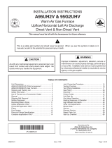
On 30-105KBtuh units, the ignition control may be located
on either the vestibule panel or the burner box panel. See
gure 1.
IGNITION CONTROL LOCATION
30-105KBTUH
LOCATION ON
VESTIBULE
LOCATION ON
BURNER BOX PANEL
FIGURE 1
30-105KBtuh Units: When present, remove the existing
control board green ground wire. Retain the ground screw.
3 - Remove and discard the existing control board and
mounting bracket (when present). Retain the screws
when control board is installed on the vestibule.
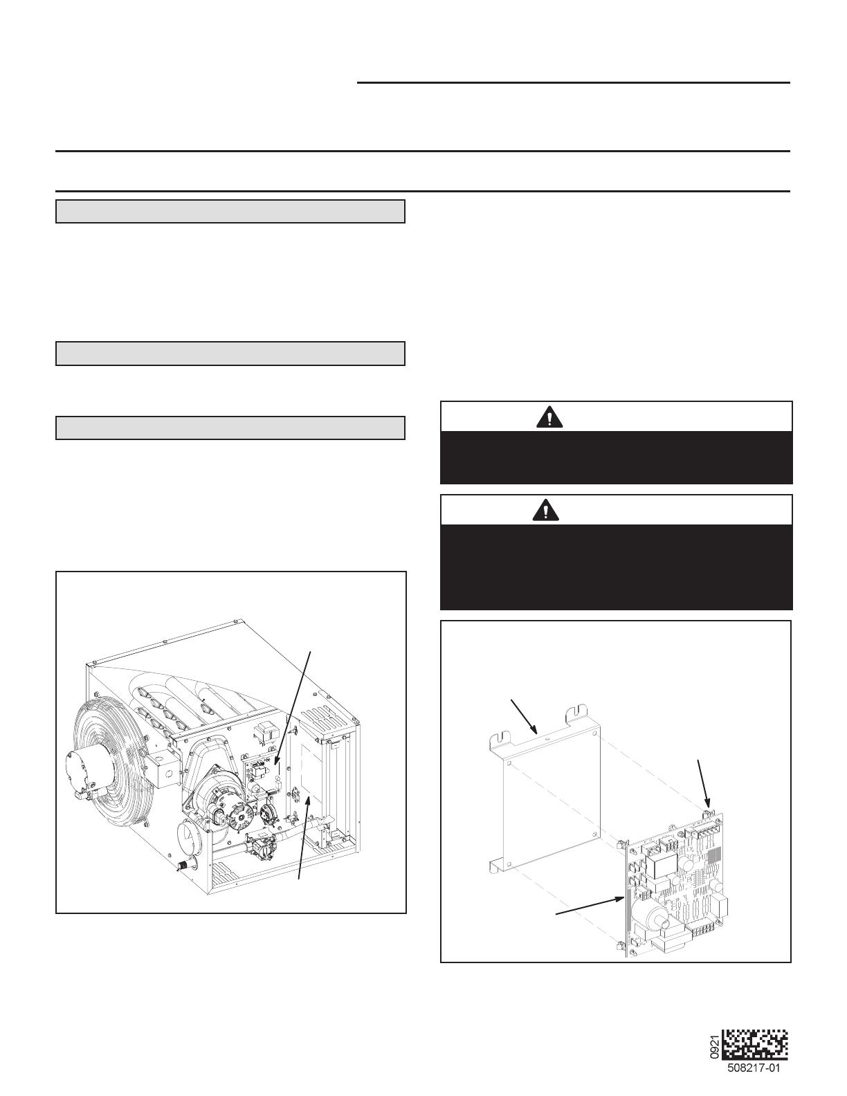
4 - 30-105KBtuh Units - Align four replacement control
board snap-lock ttings with holes on replacement
mounting bracket (provided). Press control board
onto replacement mounting bracket until it locks in
place. See gure 2.
CAUTION
As with any mechanical equipment, personal injury can
result from contact with sharp sheet metal edges. Be
careful when you handle this equipment.
WARNING
Improper installation, adjustment, alteration, service
or maintenance can cause property damage, personal
injury or loss of life. Installation and service must be
performed by a licensed professional installer (or
equivalent), service agency or the gas supplier.
SECURE CONTROL BOARD TO BRACKET
MOUNTING
BRACKET
IGNITION
CONTROL BOARD
(4) SNAP-LOCK
FITTINGS
30-105KBTUH UNITS
FIGURE 2
©2021
Page 2
5 - Boards Installed On Burner Box Panel - Use the
bottom right mounting hole on the burner panel to
position the new mounting bracket (provided). See
gure 3.
6 - 30-105KBtuh Units - Install the replacement
mounting bracket assembly in the previous location
(see previous step for assemblies located on the
burner box panel). Secure with four self-drilling
screws provided in kit. Use existing screws when
installing assembly on the vestibule.
IGNITION CONTROL LOCATED ON
BURNER BOX PANEL
60-105KBTUH
CONTROL BOARD
ASSEMBLY
BURNER BOX PANEL
USE THE EXISTING BOTTOM
RIGHT HOLE FROM THE PREVIOU
S
BOARD TO POSITION THE
REPLACEMENT BOARD
ONCE POSITIONED, SECURE
THE ASSEMBLY WITH FOUR
PROVIDED SCREWS
FIGURE 3
WARNING
Electric shock hazard.
Can cause injury or death.
Disconnect all electrical power supplies
before servicing. Access panels must be in
place during appliance operation.
SECURE CONTROL BOARD TO UNIT
125-400KBTUH UNITS
DISCARD MOUNTING
BRACKET PROVIDED IN KIT
DRILL (4)
HOLES TO 3/16”
REPLACEMENT IGNITION
CONTROL BOARD
CONTROL
MOUNTING
PANEL
FIGURE 4
7 - 125-400KBtuh Units - Drill out the board mounting
holes on the control mounting panel to 3/16”
diameter. See gure 4.
8 - 125-400KBtuh Units - Align four replacement
control board snap-lock ttings with holes on the
control mounting panel. Press control board onto
the mounting panel until it locks in place.
9 - Connect previously removed wiring onto the new
ignition control board.
30-105KBtuh units: If previously removed, install green
ground wire onto the replacement control board provided
in kit. Secure with retained ground screw.
10 - Restore electrical power to the unit.
  • Page 1 1
  • Page 2 2

Lennox 508217-01 User manual

Type
User manual

Lennox 508217-01 Ignition Control Replacement Kit is designed to replace faulty ignition control boards on Lennox 30-400KBTUH unit heaters. The kit includes a new ignition control board, mounting bracket, and all necessary hardware. It is easy to install, with clear instructions provided in the manual. The replacement kit restores the unit heater's functionality, ensuring efficient and reliable heating.

Ask a question and I''ll find the answer in the document

Finding information in a document is now easier with AI