Page is loading ...

103538-04 - 8/13 Price - $5.00
,reliobnonoitamrofnignikeesnehW.rotcartnocgnitaehruoyllac,reliobotsriaperroecivresroF
.lebaLgnitaRnonwohssarebmuNlaireSdnarebmuNledoMrelioBedivorp
rebmuNledoMrelioB
NI
rebmuNlaireSrelioBetaDnoitallatsnI
rotcartnoCgnitaeH rebmuNenohP
sserddA
DNAGNITAREPO,NOITALLATSNI
ROFSNOITCURTSNIECIVRES
ECNEDNEPEDNI
®
RELIOBDERIF-SAG
9700609

2
The New York City Department of Buildings has approved the Independence® Series boiler:
Approval No. MEA 154-93-E Vol. III.
The City of New York requires a Licensed Master Plumber supervise the installation of this product.
The Massachusetts Board of Plumbers and Gas Fitters has approved the Independence® Series boiler. See the Massachusetts
Board of Plumbers and Gas Fitters website, http://license.reg.state.ma.us/pubLic/pl_products/pb_pre_form.asp for the latest
Approval Code or ask your local Sales Representative.
The Commonwealth of Massachusetts requires this product to be installed by a Licensed Plumber or Gas Fitter.
The following terms are used throughout this manual to bring attention to the presence of hazards of various risk
levels, or to important information concerning product life.
DANGER
Indicates an imminently hazardous situation
which, if not avoided, will result in death, serious
injury or substantial property damage.
CAUTION
Indicates a potentially hazardous situation
which, if not avoided, may result in moderate or
minor injury or property damage.
WARNING
Indicates a potentially hazardous situation
which, if not avoided, could result in death,
serious injury or substantial property damage.
NOTICE
Indicates special instructions on installation,
operation, or maintenance which are important
but not related to personal injury hazards.
CAUTION
If, during normal operation, it is necessary to add water to this boiler more frequently than once a month,
consult a qualied service technician to check your system for leaks. A leaky system will increase the
volume of make-up water supplied to the boiler which can signicantly shorten the life of the boiler.
Entrained in make-up water are dissolved minerals and oxygen. When the fresh, cool make-up water is
heated in the boiler the minerals fall out as sediment and the oxygen escapes as a gas. Both can result
in reduced boiler life. The accumulation of sediment can eventually isolate the water from contacting the
cast iron. When this happens the cast iron in that area gets extremely hot and may eventually crack. The
presence of free oxygen in the boiler creates a corrosive atmosphere which, if the concentration becomes
high enough, can corrode the cast iron through from the inside. Since neither of these failure types are a
result of a casting defect the warranty does not apply. Clearly, it is in everyone's best interest to prevent this
type of failure. The maintenance of system integrity is the best method to achieve this.
NOTICE
This boiler has a limited warranty, a copy of which is included with this boiler.
It is the responsibility of the installing contractor to see that all controls are correctly installed and are
operating properly when the installation is complete.
Surface rust on cast iron sections may be attributed to the manufacturing process as well as
condensation during storage. Surface rust is normal and does not affect the performance or longevity
of a boiler.

3
CAUTION
Probe type low water cutoff devices require annual inspection and maintenance! Although these devices
are solid state in their operation, the probe is exposed to possible contamination in the boiler water and
subject to fouling. Refer to Low Water Cutoff Service Instructions for complete, step-by-step inspection and
cleaning instructions.
WARNING
This boiler requires regular maintenance and service to operate safely. Follow the instructions
contained in this manual.
Improper installation, adjustment, alteration, service or maintenance can cause property damage,
personal injury or loss of life. Read and understand the entire manual before attempting installation,
start-up operation, or service. Installation and service must be performed only by an experienced,
skilled, and knowledgeable installer or service agency.
This boiler must be properly vented.
This boiler needs fresh air for safe operation and must be installed so there are provisions for
adequate combustion and ventilation air.
The interior of the venting system must be inspected and cleaned before the start of the heating
season and should be inspected periodically throughout the heating season for any obstructions. A
clean and unobstructed venting system is necessary to allow noxious fumes that could cause injury or
loss of life to vent safely and will contribute toward maintaining the boiler’s efciency.
Installation is not complete unless a safety valve is installed. See the Piping and Trim Section of this
manual for details.
This boiler is supplied with safety devices which may cause the boiler to shut down and not re-start
without service. If damage due to frozen pipes is a possibility, the heating system should not be left
unattended in cold weather; or appropriate safeguards and alarms should be installed on the heating
system to prevent damage if the boiler is inoperative.
This boiler contains very hot water or steam under high pressure. Do not unscrew any pipe ttings
nor attempt to disconnect any components of this boiler without positively assuring the water is cool
and has no pressure. Always wear protective clothing and equipment when installing, starting up or
servicing this boiler to prevent scald injuries. Do not rely on the pressure and temperature gauges to
determine the pressure and temperature of the boiler. This boiler contains components which become
very hot when the boiler is operating. Do not touch any components unless they are cool.
Boiler materials of construction, products of combustion and the fuel contain alumina, silica, heavy
metals, carbon monoxide, nitrogen oxides, aldehydes and/or other toxic or harmful substances which
can cause death or serious injury and which are known to the state of California to cause cancer, birth
defects and other reproductive harm. Always use proper safety clothing, respirators and equipment
when servicing or working nearby the boiler.
Failure to follow all instructions in the proper order can cause personal injury or death. Read all
instructions, including all those contained in component manufacturers manuals which are provided
with the boiler before installing, starting up, operating, maintaining or servicing.
Keep boiler area clear and free from combustible materials, gasoline and other ammable vapors or
liquids.
All cover plates, enclosures and guards must be in place at all times.

4
Figure 1: Dimensional Drawing

5
Table 1: Dimensional Data
Heating Surface: 4.35 sq. ft. per ueway (steam); 5.72 sq. ft. per ueway (water)
Boiler
Model
Approx.
Shipping
Weight
Lbs.
Dimensions (in inches)
Recommended
Min. Round
Chimney Size
(Diameter x Height)
(1)
Gas
Conn.
(NPT)
Water Volume
(Gal.)
'A' 'B' 'C' 'D' 'E' 'F' 'G'
Steam
Boiler
(3)
IN3I 350 14-1/2
40
33-3/4 4
40-1/4
4-3/4
7-1/4 4" x 15 ft.
1/2"
5.1 3.9
IN4I 420 17-3/4 34-3/4 5 8-7/8 5" x 15 ft. 6.5 5.0
IN5I 485 21
35-3/4 6 5-1/4
10-1/2
6" x 15 ft.
7.9 6.1
IN6I 555 24-1/4 12-1/8 9.3 7.2
IN7I 620 27-1/2
36-3/4 7
7-1/2
13-3/4
7" x 15 ft.
3/4"
10.7 8.3
IN8I 690 30-3/4 15-3/8 12.1 9.4
IN9I 760 34 37-3/4
8
17
8" x 15 ft.
13.5 10.5
IN10 815 37-1/4
45 38-3/4 45-1/2
18-5/8
3/4"
(2)
14.9 11.6
IN11 885 40-1/2
9
20-1/4
9" x 15 ft.
16.3 12.7
IN12 955 43-3/4 21-7/8 1" 17.7 13.8
(1) 15' chimney height is from bottom of Draft Hood opening to top of Chimney.
(2) Gas connection size on IN10-IN11 Continuous Ignition (Standing Pilot) is 1 NPT.
(3) Steam boiler's "steamable water volume": water volume from NWL (normal water level) to low water cutoff level.
TABLE OF CONTENTS
I. Pre-Installation.......................................................................................... 7
II. Knockdown Boiler Assembly..................................................................... 9
III. Semi-Pak Boiler Assembly........................................................................ 13
IV. Packaged Boiler Assembly......................................................................... 15
V. Piping and Trim......................................................................................... 16
VI. Gas Piping................................................................................................ 19
VII. Venting...................................................................................................... 21
VIII. Electrical .................................................................................................. 24
IX. System Start-up ...................................................................................... 34
X. Service and Maintenance ........................................................................ 44
XI. Repair Parts ............................................................................................. 50
Appendix B - Figures................................................................................ 69
Appendix C = Tables................................................................................. 71

6
Table 2: Trim and Control Installation in Section Tappings
Tapping
Size
(NPT)
Steam Boiler with Probe L.W.C.O.
Steam Boiler with
Float L.W.C.O.
A 2 Supply Supply
B ½ Bush to ¼ Pressure Gauge Plug
C ½ Gauge Glass
Nipple & ½ Union Gauge, L.W.C.O. Street Elbow,
Syphon & Limit
D 2 Return Return
E ¾ 3" Nipple & Street Elbow Safety Valve 3" Nipple & Street Elbow Safety Valve
F 2 Bush to ¾ Drain Valve and/or Optional Return Bush to ¾ Drain Valve and/or Optional Return
G 2
Optional Supply (IN3I-6)
Required Supply (IN7I-12)
Optional Supply (IN3I-6)
Required Supply (IN7I-12)
H ¾ Bush to ¼ & Syphon Limit Bush to ¼ Pressure Gauge
J ¾ Not Applicable Not Applicable
K ¾ Low Water Cutoff Plug
L 1
Factory Plugged
Surface Blow-Off
Factory Plugged
Surface Blow-Off
M 1¼
Factory Plugged
Alliance SL™ Return
Factory Plugged
Alliance SL™ Return
N 1¼
Factory Plugged
Alliance SL™ Supply
Factory Plugged
Alliance SL™ Supply
P ¾
Factory Plugged
Alliance SL™ Limit
Factory Plugged
Alliance SL™ Limit
Figure 2: Section Tappings

7
I. Pre-Installation
A. Inspect shipment carefully for any signs of damage. All
equipment is carefully manufactured, inspected and
packed. Our responsibility ceases upon delivery of
boiler to carrier in good condition. Any claim for
damage or shortage in shipment must be led
immediately against carrier by consignee. No claims for
variances or shortages will be allowed by Boiler
Manufacturer, unless presented within sixty (60) days
after receipt of equipment.
B. The installation must conform to the requirements of
the authority having jurisdiction. In the absence of such
requirements, installation must conform to the National
Fuel Gas Code, ANSI Z223.1/NFPA 54, and/or Natural
Gas and Propane Installation Code, CAN/CSA B149.1.
Where required by the authority having jurisdiction, the
installation must conform to the Standard for Controls
and Safety Devices for Automatically Fired Boilers,
ANSI/ASME No. CSD-1.
C. Boiler is design certied for installation on combustible
ooring. Boiler must not be installed on carpeting.
D. Provide clearance between boiler jacket and
combustible material in accordance with local re
ordinance. See Figure 3 for minimum listed clearance
to combustible material.
Recommended service clearance is 24 (61.0 cm) inches
from left side, right side, and front. Additional clearance
may be required on left side if optional tankless heater
is installed. Service clearances may be reduced to
minimum clearances to combustible materials.
Provide 1/2" (1.3 cm) between combustible
construction and steam/hot water piping.
E. Install boiler on level oor as close to chimney as
possible. For basement installation provide a solid base,
such as concrete, steel or masonry if oor is not level or
if water may be encountered on oor around boiler.
F. Protect gas ignition system components from water
(dripping, spraying, rain, etc.) during boiler operation
and service (circulator replacement, control
replacement, etc.).
G. Provide combustion and ventilation air in accordance
with applicable provisions of local building codes, or
with "Air for Combustion and Ventilation" section of
the National Fuel Gas Code, ANSI Z223.1/NFPA 54, or
Sections 8.2, 8.3 or 8.4 of Natural Gas and Propane
Installation Code, CAN/CSA B149.1.
WARNING
Adequate combustion and ventilation air must be
provided to assure proper combustion.
The following guideline is based on the National Fuel
Gas Code, NFPA 54/ANSI Z223.1.
1. Determine volume of space (boiler room). Rooms
communicating directly with space (through
openings not furnished with doors) are considered
part of space.
Volume [ft³] = Length [ft] x Width [ft] x Height [ft]
2. Determine Total Input of all appliances in space.
Round result to nearest 1,000 Btu per hour (Btuh).
3. Determine type of space. Divide Volume by Total
Input.
a. If result is greater than or equal to 50 ft³ per
1,000 Btuh, space is considered an unconned
space.
b. If result is less than 50 ft³ per 1,000 Btuh, space
is considered a conned space.
4. Determine building type. A building of unusually
tight construction has the following characteristics:
a. Walls and ceiling exposed to outside atmosphere
have a continuous water vapor retarder with a
rating of 1 perm or less with openings gasketed
and sealed, and
b. Weather-stripping has been added on openable
windows and doors, and
c. Caulking or sealants applied in joints around
window and door frames, between sole plates
and oors, between wall-ceiling joints, between
wall panels, at plumbing and electrical
penetrations, and at other openings.
WARNING
If you do not follow these instructions exactly,
a re or explosion may result causing property
damage or personal injury.
DANGER
Do not install boiler where gasoline or other
ammable vapors or liquids, or sources
of hydrocarbons (i.e. bleaches, cleaners,
chemicals, sprays, paint removers, fabric
softeners, etc.) are used or stored.
NOTICE
Due to the low water content of the boiler, mis-
sizing of the boiler with regard to the heating
system load will result in excessive boiler
cycling and accelerated component failure. U.S.
Boiler Company DOES NOT warrant failures
caused by mis-sized boiler applications. DO
NOT oversize the boiler to the system.

8
Figure 3: Clearance to Combustible Materials
5. For boiler located in an unconned space in a
building of other than unusually tight construction,
adequate combustion and ventilation air is normally
provided by fresh air inltration through cracks
around windows and doors.
6. For boiler located within unconned space in
building of unusually tight construction or within
conned space, provide outdoor air through two
permanent openings which communicate directly or
by duct with the outdoors or spaces (crawl or attic)
freely communicating with the outdoors. Locate one
opening within 12 inches of top of space. Locate
remaining opening within 12 inches of bottom of
space. Minimum dimension of air opening is 3
inches. Size each opening per following:
a. Direct communication with outdoors. Minimum
free area of 1 square inch per 4,000 Btu per hour
input of all equipment in space.
b. Vertical ducts. Minimum free area of 1 square
inch per 4,000 Btu per hour input of all
equipment in space. Duct cross-sectional area
shall be same as opening free area.
c. Horizontal ducts. Minimum free area of 1 square
inch per 2,000 Btu per hour input of all
equipment in space. Duct cross-sectional area
shall be same as opening free area.
Alternate method for boiler located within conned
space. Use indoor air if two permanent openings
communicate directly with additional space(s) of
sufcient volume such that combined volume of all
spaces meet criteria for unconned space. Size each
opening for minimum free area of 1 square inch per
1,000 Btu per hour input of all equipment in spaces,
but not less than 100 square inches.
7. Ventilation Duct Louvers and Grilles. Equip outside
openings with louvers to prevent entrance of rain
and snow, and screens to prevent entrance of insects
and rodents. Louvers and grilles must be xed in
open position or interlocked with equipment to open
automatically before burner operation. Screens must
not be smaller than ¼ inch mesh.
Consider the blocking effect of louvers, grilles and
screens when calculating the opening size to provide
the required free area. If free area of louver or grille
is not known, assume wood louvers have 20-25
percent free area and metal louvers and grilles have
60-75 percent free area.
H. Do not install boiler where gasoline or other ammable
vapors or liquids, or sources of hydrocarbons (i.e.
bleaches, cleaners, chemicals, sprays, paint removers,
fabric softeners, etc.) are used or stored.
I. Pre-Installation (continued)

9
Figure 4: Base Gasket Installation
II. Knocked-Down Boiler Assembly
WARNING
Installation of this boiler should be undertaken
only by trained and skilled personnel from a
qualied service agency.
A. Install Base-Burner-Manifold Assembly
1. Base-Burner-Manifold is shipped assembled from
factory (Gas Valve and Pilot/Burner Assembly is
shipped in the "Gas Controls Carton").
2. Unpack base assembly and place in location where
boiler is to be installed (Refer to Section I: Pre-
Installation).
B. Install assembled cast iron sections on base assembly:
1. Install (4) 5/16" x ¼" self-tapping screws through
(4) holes in upper base ange with screw heads on
underside of ange. Note: Screws are located in
ber gasket parts bag.
2. Install ceramic ber gasket. See Figure 4.
3. Position boiler above base with lugs cast in boiler
sections centered over screws protruding from top of
base. Lower boiler onto base taking care not to
disturb ceramic ber gasket. Secure with 5/16"
locknuts and washers provided. See Figure 5.
4. Loosen nuts on tie rods until only nger tight.
5. If Steam boiler less tankless heater, proceed to
Paragraph C.
Note: If tankless heater is not installed, heater opening
cover plate must remain in place.
C. Test boiler for leaks before connecting to system and
installing controls, trim and jacket.
1. Attach pressure gauge (capable of indicating 30 psi)
on boiler.
Figure 5: Section Assembly Attachment
Figure 6: Hydrostatic Pressure Test
2. Attach ll valve and piping to return tapping and
purge valve to supply tapping. See Figure 6.
3. Install plugs in remaining tappings.
4. Fill boiler completely with water by venting air
through purge valve. Close purge valve and apply
water pressure of at least 10 psi but not exceeding
30 psi gauge pressure.
5. Examine boiler carefully inside and outside for leaks
or damage due to shipment or handling.

10
Figure 9: Jacket Assembly
Figure 7: Canopy Gasket Installation
Figure 8: Canopy Installation
D. Install Canopy.
1. Install ½" thick x 1" wide ceramic ber gasket. See
Figure 7.
2. Position canopy on ceramic ber gasket. See Figure
8.
3. Attach canopy using ¼" carriage bolts, nuts, and
washers provided.
E. Inspect joints between sections. They were factory
sealed. If there are any openings due to shipment or
handling, reseal with boiler putty.
F. Install Jacket. See Figure 9.
1. Models IN7I-IN12: remove 3 inch diameter
knockouts in jacket top panels.
2. Raise rear panel under rear ange of canopy and rest
on oor. Position rear panel and secure to jacket side
panels with sheet metal screws. For Models IN10-
IN12, secure jacket upper rear panels to side panels
with sheet metal screws.
3. Secure both jacket side panels to base with sheet
metal screws.
4. Position front tie bar and secure to jacket side panels
with sheet metal screws.
5. Position vestibule panel and secure to side panels
with sheet metal screws.
6. Attach Rating Label and Vent Damper Instruction
Label at designated locations on vestibule panel.
7. Install top panels by placing over and around outside
of side and rear panels. Seat fully and secure with
sheet metal screws.
II. Knocked-Down Boiler Assembly (continued)

11
Figure 12: Pilot and Gas Piping, Intermittent
Ignition (EI) (IN3I through IN11 Only)
Figure 11: Pilot and Gas Piping, Continuous Ignition
(Standing Pilot) (IN10 through IN12 Only)
Figure 13: Pilot and Gas Piping, Intermittent
Ignition (EI) (IN12 Only)
8. Install black plastic rings into 1-3/32 inch diameter
holes located below upper louvers of front
removable door.
9. Install front removable door by engaging upper side
edges of panel with side receiving anges, sliding
up and under top panel ange - seating front door
fully - then sliding down to engage bottom ange
behind lower front tie bar.
Figure 10: Combustion Chamber
G. Install Pilot/Burner Assembly (shipped in Gas
Controls Carton). See Figure 10.
1. Remove jacket front removable door.
a. Remove burner access panel located above
burners.
b. Install Pilot/Burner Assembly where noted on
gas manifold.
i. Insert rear of burner in burner tray slot.
ii. Position burner over the orice.
NOTE: The burner to the right may need to
be lifted from the orice to install pilot/
burner assembly. Reinstall lifted burner
over the orice.
c. Reinstall burner access panel.
H. Install Gas Valve on main gas burner assembly (if not
factory assembled). See Figure 11, 12 or 13.
1. Connect gas valve to manifold.
2. Connect pilot tubing from pilot burner to gas valve
pilot tapping.
3. Continuous Ignition (standing pilot): connect
thermocouple to gas valve.
I. Install Blocked Vent Switch with sheet metal screws.
1. Models IN3I - IN9I. Install on rear ange of canopy.
See Figure 14.
2. Models IN10 - IN12. Install on right side of draft
hood. See Figure 15. Reset switch must face away
from draft hood relief opening.
3. Attach black 18-2 harness to Blocked Vent Switch
terminals. Use end with two fully insulated
disconnects.
4. Secure harness to right side jacket panel with clamp.
5. Insert harness through ¾ inch hole in right side
jacket panel. Secure with strain relief bushing.
II. Knocked-Down Boiler Assembly (continued)

12
Figure 15: Blocked Vent Switch Installation,
IN10 through IN12
Figure 14: Blocked Vent Switch Installation,
IN3I through IN9I
J. Intermittent Ignition (EI): Install Ignition Module.
1. Mount ignition module mounting bracket to inside
of right side panel using (2) #6 x ¾" sheet metal
screws provided.
2. Mount ignition module to bracket using (2) #8 x ½"
sheet metal screws provided.
3. Install (3) wire harness from ignition module to gas
valve as shown in wiring diagrams.
K. Continue to Section III: Semi-Pak Boiler Assembly,
Paragraph C.
II. Knocked-Down Boiler Assembly (continued)

13
III. Semi-Pak Boiler Assembly
WARNING
Installation of this boiler should be undertaken
only by trained and skilled personnel from a
qualied service agency.
A. Remove Crate
1. Remove all hold down screws and brackets.
2. Slide boiler to rear of skid and carefully remove
from crate skid onto 2 inch thick piece of wood and
then onto oor. Do not bump boiler jacket against
oor.
3. Do not drop boiler at any time.
B. Move Boiler To Permanent Position. Refer to Section
I: Pre-Installation.
C. Identify Trim and Controls
FIRST - Determine controls ordered with boiler and
refer to appropriate section(s) following:
There are two ordering methods for trim and controls:
1. EZ–Connect Carton includes trim, controls, wiring
and wiring instructions for installation.
2. Separate Trim Carton and Control Carton. Only
wiring requiring special connections is provided.
For wiring requirements, refer to Section VIII:
Electrical and appropriate wiring diagram.
D. Install Trim and Controls
Refer to appropriate paragraphs (following) for trim
and controls to be installed.
1. Steam Boiler with Probe Low Water Cutoff
a. Install pressure limit control into Tapping "H"
with siphon, ¾" x ¼" hex bushing, ¾" elbow and
¾" x 3" nipple provided. See Figures 1 and 2.
DO NOT TWIST CONTROL. Use wrench on
hex tting located at bottom of control. See
Figure 16.
b. The L404F pressure limit employs a snap action
switch and does not require leveling. See Figure
16.
c. Install pressure gauge into Tapping "B" (½ NPT
bushed to ¼ NPT). See Figures 1 and 2. Tighten
with wrench applied to square shank on back of
gauge. DO NOT APPLY PRESSURE ON
GAUGE CASE since this may destroy
calibration of gauge.
d. Install Low Water Cutoff Probe into Tapping "K"
(¾ NPT). HANDLE PROBE WITH CARE.
e. Attach Low Water cutoff Control to Probe by
following instructions packed with control.
Figure 16: L404F Pressure Limit Control
f. Install gauge glass ttings into Tappings "C"
(½ NPT). See Figures 1 and 2. Lower tting has
small drain valve.
g. Install gauge glass and protective rods in ttings.
h. Attach "Lowest Permissible Water Level" Plate
with sheet metal screws in location indicated in
Figure 9.
i. Attach "Frequent Water Addition" Label above
the "Lowest Permissible Water Level" Plate.
2. Steam Boiler with McDonnell & Miller 67 Float
Low Water Cutoff
a. Install Low Water Cutoff, see instructions packed
with control.
i. Screw brass nipples with union halves into
Tappings "C" (½ NPT). See Figure 1 and 2.
ii. Attach Gauge Glass/Low Water Cutoff
Assembly to union halves.
iii. Afx Blow-Down Card to Jacket Left Side
Panel adjacent to low water cutoff.
iv. Provide blow down discharge piping.
b. Attach street elbow siphon and pressure limit
control to low water cutoff. DO NOT TWIST
CONTROL. Use wrench on hex tting located at
bottom of control.
c. The L404F pressure limit employs a snap action
switch and does not require leveling. See Figure
16.
d. Install pressure gauge into Tapping "H" (¾ NPT
bushed to ¼ NPT). See Figures 1 and 2. Tighten
with wrench applied to square shank on back of
gauge. DO NOT APPLY PRESSURE ON
GAUGE CASE since this may destroy
calibration of gauge.
e. Attach "Lowest Permissible Water Level" Plate
with sheet metal screws in location indicated in
Figure 9.

14
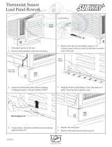
Figure 18: Thermostat Isolation Relay Attachment
f. Attach "Frequent Water Addition" Label above
the "Lowest Permissible Water Level" Plate.
3. All Steam Boiler Controls Cartons
a. Install Junction Box. See Figure 17A.
i. Remove center knockout in rear of Junction
Box and insert black plastic snap bushing in
hole.
ii. Install mounting bracket to rear of Junction
Box with two (2) blunt sheet metal screws
provided.
iii. Align center and mounting holes of Junction
Box with upper front corner of jacket left
side panel.
iv. Install Junction Box to jacket from inside
vestibule area with two (2) blunt sheet metal
screws provided.
b. Mount transformer on Junction Box. For
Canadian boiler provide strain relief by loosely
securing Transformer to Junction Box with wire
tie inserted through Transformer plate and a
Junction Box mounting hole. See Figure 17B.
c. Fork connector on yellow wire of gas valve
harness must be removed and wire stripped
before making wire connections. Refer to
Section VIII for wiring.
d. Steam Boilers only. Secure the R8222
Thermostat Isolation Relay to upper left corner of
jacket vestibule panel with sheet metal screws
provided. See Figure 18.
E. Continue to Section IV. Packaged Boiler Assembly,
Paragraph E.
Figure 17B: Junction Box and Transformer
Assembly
Figure 17A: Junction Box and Mounting Bracket
Assembly
III. Semi-Pak Boiler Assembly (continued)

15
Figure 20: Securing Draft Hood to Canopy
A. Remove crate and move boiler to permanent position
as detailed in Section III: Semi-Pak Boiler Assembly.
B. Remove Jacket Front Panel. See Figure 35.
C. Remove poly bag from vestibule area.
D. On Steam Boilers with probe low water cutoff the
L404 pressure limit/control has been packed in the
vestibule area.
1. Screw the pressure limit/control onto the syphon.
DO NOT TWIST CONTROL. Use wrench on hex
tting at bottom of control. See Figure 16.
2. Snap the electrical conduit from the adjacent
junction box into the hole in the control.
3. Open the control's clear cover and attach the two (2)
wires in the conduit to the two (2) unused screw
terminals.
IV. Packaged Boiler Assembly
Figure 19: Draft Hood Attachment
E. Install Jacket Front Panel.
F. Install Draft Hood. Models IN3I through IN9I.
1. Locate and open "Rear Draft Hood Carton".
2. Position Draft Hood on Canopy Rear Flange. See
Figure 19. Top canopy ange must fully engage
"U"-shaped draft hood ange for proper installation
and operation. Care must be taken to assure that
draft hood is level.
3. Secure Rear Draft Hood to Canopy with wing nuts
provided. See Figure 20.
WARNING
Installation of this boiler should be undertaken
only by trained and skilled personnel from a
qualied service agency.
WARNING
Do not alter boiler draft hood or place any
obstruction or non-approved damper in the
breeching or vent system. Flue gas spillage can
occur. ETL/ETLC certication will become void.

16
V. Piping and Trim
A. Design and install boiler and system piping to prevent
oxygen contamination of boiler water. Sources of
oxygen contamination are system leaks requiring
addition of makeup water, ttings, and oxygen
permeable materials in distribution system. Eliminate
oxygen contamination by repairing system leaks,
repairing ttings, using nonpermeable materials in
distribution system, and eliminating open tanks in
system, or isolating boiler from system with heat
exchanger.
B. Install Safety Valve in Tapping "E" (¾ NPT). See
Figure 21. Use ¾ NPT x 3" nipple and ¾ NPT elbow
provided. Safety Valve must be installed with spindle in
vertical position.
Figure 21: Trim Installation
WARNING
Safety valve discharge piping must be piped
such that the potential of severe burns is
eliminated. DO NOT pipe in any area where
freezing could occur. DO NOT install any shut-
off valves, plugs or caps. Consult Local Codes
for proper discharge piping arrangement.
C. Install Drain Valve in Tapping "F" (2 NPT bushed to
¾ NPT). See Figure 21.
D. Connect supply and return piping to heating system.
Maintain minimum ½ inch clearance from combustible
materials.
1. For STEAM HEATING see Figure 22. Consult
I=B=R, "Residential Hydronic Heating Installation
and Design Guide".
2. If boiler is used in connection with refrigeration
systems, boiler must be installed with chilled
medium piped in parallel with heating boiler using
appropriate valves to prevent the chilled medium
from entering the boiler. See Figure 23. Also
consult I=B=R, "Residential Hydronic Heating
Installation and Design Guide".
3. Boiler piping system of hot water boiler connected
to heating coils located in air handling units where
they may be exposed to refrigerated air circulation
must be equipped with ow control valves or other
automatic means to prevent gravity circulation of
boiler water during cooling cycle.
NOTICE
Before using copper for steam piping, consider the following characteristics of copper piping:
1) high coefcient of thermal expansion can induce mechanical stresses and cause expansion/
contraction noises if not accounted for in the piping system design and installation,
2) high heat transfer rate (heat loss) of uninsulated copper piping must be included in the normal
piping and pickup factors used to size the boiler,
3) soldering or brazing pastes and uxes that end up in the system can cause poor heat transfer,
surging, an unsteady water line and wet steam if not thoroughly removed during the boil out
procedure and,
4) galvanic corrosion of the adjoining metal may occur due to dissimilar metals in certain water
chemistries if dielectric unions are not used.
WARNING
Failure to properly pipe boiler may result in improper operation and damage to boiler or structure.
Do not use softened water in steam boilers. Accelerated boiler corrosion will result. Tie in fresh water
supply to the boiler upstream of a water softener.
Oxygen contamination of boiler water will cause corrosion of iron and steel boiler components, and
can lead to boiler failure. U.S. Boiler Company’s Standard Warranty does not cover problems caused
by oxygen contamination of boiler water or scale (lime) build-up caused by frequent addition of water.

17
Figure 22: Steam Boiler Piping (Minimum)
NOTICE
Failure to pipe boiler as specied in this manual may result in excessive system noise, water line uctuations and water carry over.
V. Piping and Trim (continued)

18
Figure 24: Recommended Piping for
Indirect Water Heater Figure 25: Tankless Heater Piping
Figure 23: Recommended Piping for Combination
Heating and Cooling (Refrigeration) Systems
F. Tankless Heater (if used). See Figure 25.
1. Install automatic tempering or mixing valve to
prevent delivery of scalding hot water to xtures.
Higher temperature water for dishwashers and
automatic washers is possible by piping hot water
from heater prior to entering mixing valve. Install
per manufacturer's instructions.
WARNING
Install automatic mixing valve at tankless heater
outlet to avoid risk of burns or scalding due to
excessively hot water at xtures.
2. Install ow regulator. Match regulator rating to
tankless heater rating. Install in cold water inlet
below and minimum 3 feet downstream of tankless
heater inlet.
3. Install water softener in areas of hard water, this will
reduce mineral deposits which could hinder heat
transfer and delivery of hot water.
G. If a long term pressure test of the hydronic system is
required, the boiler should rst be isolated to avoid a
pressure loss due to the escape of air trapped in the
boiler.
To perform a long term pressure test including the
boiler, ALL trapped air must rst be removed from the
boiler.
A loss of pressure during such a test, with no visible
water leakage, is an indication that the boiler contained
trapped air.
4. If a tankless heater coil is used, connect water lines
to ¾ NPT tappings in coil plate.
E. Alliance SL™ Indirect Water Heater (if used). Refer
to Alliance SL™ Installation, Operating and Service
Instructions for additional information. See Figure 24
for piping recommendations.
1. Supply and Return Piping. Connect supply piping to
Tapping "N" (1¼ NPT) and return piping to Tapping
"M" (1¼ NPT). Install zone circulator and strainer
in supply piping. Install check valve to prevent
gravity circulation of boiler water.
2. Limit. See Figure 21. Install temperature limit
control (Honeywell L4006A or equal) in Tapping
"P" (¾ NPT). See Figure 2. Set at 180°F to prevent
steam production during non-space heating periods.
V. Piping and Trim (continued)

19
VI. Gas Piping
WARNING
Failure to properly pipe gas supply to boiler may
result in improper operation and damage to the
boiler or structure. Always assure gas piping is
absolutely leak free and of the proper size and
type for the connected load.
An additional gas pressure regulator may be
needed. Consult gas supplier.
A. Size gas Piping. Design system to provide adequate
gas supply to boiler. Consider these factors:
1. Allowable pressure drop from point of delivery to
boiler. Maximum allowable system pressure is ½
psig. Actual point of delivery pressure may be less;
contact gas supplier for additional information.
Minimum gas valve inlet pressure is indicated on
Rating Label, located on the vestibule panel.
2. Maximum gas demand. Table 3 lists boiler input
rate. Also consider existing and expected future gas
utilization equipment (i.e. water heater, cooking
equipment).
3. Lengthofpipingandnumberofttings.Referto
Table 4 for maximum capacity of Schedule 40 pipe.
Table5listsequivalentlengthforstandardttings.
4. Correctionsforthespecicgravityofnaturalgas
can be found in Table 6.
Table 3: Rated Input
For materials or conditions other than those listed
above, refer to the National Fuel Gas Code, ANSI
Z223.1/NFPA 54 and/or Natural Gas and Propane
Installation Code, CAN/CSA B149.1, or size system
using standard engineering methods acceptable to
authority having jurisdiction.
WARNING
Failure to use proper thread compounds on all
gas connectors may result in leaks of ammable
gas.
WARNING
Gas supply to boiler and system must be
absolutely shut off prior to installing or servicing
boiler gas piping.
B. Connect boiler gas valve to gas supply system.
1. Use methods and materials in accordance with local
plumbing codes and requirements of gas supplier. In
absence of such requirements, follow the National
Fuel Gas Code, ANSI Z223.1/NFPA 54 and/or
Natural Gas and Propane Installation Code, CAN/
CSA B149.1.
2. Use thread (joint) compounds (pipe dope) resistant
toactionofliqueedpetroleumgas.
3. Install sediment trap, ground-joint union and manual
shut-off valve upstream of boiler gas valve and
outside jacket. See Figure 26.
Figure 26: Recommended Gas Piping
Boiler
Model
Number
Rated Capacity
[cubic feet per hour]
Gas
Connection
Size
Natural LP/Propane
IN3I 62 24¾ ½
IN4I 105 42 ½
IN5I 140 56 ½
IN6I 175 70 ½
IN7I 210 84 ¾
IN8I 245 98 ¾
IN9I 280 112 ¾
IN10 315
(1)
--- ¾
(2)
IN11 349
(1)
--- ¾
( 2)
IN12 385 --- 1
(1)
Reduce IN10 - IN11 input by 3% in Canada
(2)
Gas connection size is 1" on IN10 and IN11
Continuous Ignition (Standing Pilot)

20
Table 5: Fitting Equivalent Lengths
Table 6: Specic Gravity Correction Factors for
Natural Gas
4. All above ground gas piping upstream from manual
gas valve must be electrically continuous and
bonded to a grounding electrode. Do not use gas
piping as a grounding electrode. Refer to the
National Electrical Code, ANSI/NFPA 70 and/or
CSA C22.1 Electrical Code.
C. Pressure Test. The boiler and its gas connection must
be leak tested before placing boiler in operation.
1. Protect boiler gas valve. For all testing over ½ psig
(3.5 kPa), boiler an its individual shut-off valve
must be disconnected from gas supply piping. For
testing at pressure equal to or less than ½ psig (3.5
kPa), isolate boiler from gas supply piping by
closing boiler's individual manual shut-off valve.
2. Using soap solution, or similar non-combustible
solution, electronic leak detector or other approved
method. Check that boiler gas piping valves, and all
other components are leak free. Eliminate any
leaks.
Table 4: Maximum Capacity of Schedule 40 Pipe in CFH for Natural Gas Pressures of 0.5 psig or Less
NOTICE
USA boilers built for installation at altitudes greater than 2,000 feet above sea level have been specially oriced
to reduce gas input rate 4 percent per 1,000 feet above sea level per the National Fuel Gas Code, NFPA 54/
ANSI Z223.1. Canadian boilers' orice sizing is indicated on the rating label. High altitude boiler models are
identiable by the third digit in the model number sufx on the rating label:
_IN_ _ _ - _ _ 2 less than 2000 ft. elevation
_IN_ _ _ - _ _ 4 2000 to 4500 ft. elevation (Canada)
_IN_ _ _ - _ _ 5 2000 to 5000 ft. elevation (USA)
Fitting
Nominal Pipe Size
½ ¾ 1 1¼
45° Ell 0.7 1.0 1.2 1.6
90° Ell 1.6 2.1 2.6 3.5
Tee
(As Elbow)
3.1 4.1 5.2 6.9
Specic
Gravity
Correction
Factor
Specic
Gravity
Correction
Factor
0.50 1.10 1.30 1.07
0.55 1.04 1.40 1.04
0.60 1.00 1.50 1.00
0.65 0.96 1.60 0.97
0.70 0.93 1.70 0.94
0.75 0.90
0.80 0.87
Length\
[Feet]
0.3 inch w.c. Pressure Drop 0.5 inch w.c. Pressure Drop
½ ¾ 1 1¼ ½ ¾ 1 1¼
10 132 278 520 1,050 175 360 680 1,400
20 92 190 350 730 120 250 465 950
30 73 152 285 590 97 200 375 770
40 63 130 245 500 82 170 320 660
50 56 115 215 440 73 151 285 580
60 50 105 195 400 66 138 260 530
70 46 96 180 370 61 125 240 490
80 43 90 170 350 57 118 220 460
90 40 84 160 320 53 110 205 430
100 38 79 150 305 50 103 195 400
DANGER
Do not use matches, candles, open ames or
other ignition source to check for leaks.
VI. Gas Piping (continued)
/