Page is loading ...

ISO 9001
Products are manufactured
in ISO registered facilities.
Intelligent Assembly Solutions
www.dukane.com/us
Dukane Part No. 403 - 591 - 00
iQ Series
ULTRASONIC GENERATOR/POWER SUPPLY
Auto-Plus
User’s Manual
Dukane Intelligent Assembly Solutions • 2900 Dukane Drive • St. Charles, Illinois 60174 USA • TEL (630) 797
-
4900 • FAX (630) 797
-
4949
AUTOMATED
PRESS
HAND PROBE

Page ii
iQ Series, Auto-Plus User’s Manual
Dukane Manual Part No. 403-591-00
Printed in the United States of America.
Dukane Part Number: 403-591-00
Dukane ultrasonic equipment is manufactured under one or more of the following U.S. Patents:
(* = Inactive)
3,780,926 * 4,131,505* 4,277,710* 5,798,599 5,880,580 6,984,921 7,225,965 7,475,801,
7,819,158 and, 8,052,816
Copyright © 2014 Dukane Intelligent Assembly Solutions
2900 Dukane Drive
St. Charles, IL 60174 USA
Notice of Rights:
All rights reserved. No part of this manual including the interior design, cover design and icons may be
reproduced, transmitted or utilized in any form or by any means, electronic, mechanical, photocopying,
recording, or by any information storage and retrieval system, without written permission from Dukane
Corporation.
Notice of Liability:
The information contained in this manual is distributed on an “As is” basis, without warranty. While
every precaution has been taken in the preparation of this manual, Dukane Corporation shall not have
any liability to any person or entity with respect to any liability, loss, or damage caused or alleged to be
caused directly or indirectly by the instructions contained in this manual, or by the hardware products
described herein.
Specications subject to change without notice.
This user’s manual documents product features, hardware, and controls software available at the
time this user's manual was published.

Page iii
Dukane Manual Part No. 403-591-00
Revision History
Revision Revision
Number Summary Date
- 00 Original release. March 14, 2014

Page iv
iQ Series, Auto-Plus User’s Manual
Dukane Manual Part No. 403-591-00
This page intentionally left blank

Page v
Dukane Manual Part No. 403-591-00
Contents
Section 1- Introduction .......................1
Section 2- Health and Safety ...................7
Section 3- Installation .......................13
Connecting Cables.......................................17
MPC Module Installation Guide .............................22
Section 4 - System Operation . . . . . . . . . . . . . . . . . 25
iQ Auto-Plus System Operational Test .......................28
LED Indication ..........................................32
Section 5 - Options..........................33
Heat Sink ..............................................35
Computer Interface ......................................36
Section 6 - Automation Interface ..............37
Input/Output Connection Examples..........................39
E-Stop Wiring and Automation System Safety Circuit ............43
......................................................44
Section 7 - Contacting Dukane ................47
Section 8 - Specications ....................33
Generator Outline Drawing ................................53
Weight, Operating Environment.............................54
AC Power Requirements ..................................55
Ultrasound Pressure .....................................56
Interpreting the Model Number .............................57
iQ Auto to iQ Auto Plus Inputs /Outputs Comparison.............58
Section 9 - Appendices ......................61
Index .....................................65
TM

Page vi
iQ Series, Auto-Plus User’s Manual
Dukane Manual Part No. 403-591-00
This page intentionally left blank

Page 1
Section 1 – Introduction
Dukane Manual Part No. 403-591-00
SECTION 1
Introduction
General User Information . . . . . . . . . . . . . . . . . . 3
Read The Manual First . . . . . . . . . . . . . . . . . . . . . .3
Notes, Cautions and Warnings . . . . . . . . . . . . . . . . . .3
Drawings and Tables . . . . . . . . . . . . . . . . . . . . . . . 3
Generator Overview . . . . . . . . . . . . . . . . . . . . . 4
Key Generator Features . . . . . . . . . . . . . . . . . . . 4
Thermal Considerations . . . . . . . . . . . . . . . . . . . 5

Page 2
iQ Series, Auto-Plus User’s Manual
Dukane Manual Part No. 403-591-00
This page intentionally left blank

Page 3
Section 1 – Introduction
Dukane Manual Part No. 403-591-00
General User Information
Read This Manual First
Before operating your ultrasonic system, read this User’s
Manual to become familiar with the equipment. This will
ensure correct and safe operation. The manual is organized
to allow you to learn how to safely operate this equipment.
The examples given are chosen for their simplicity to il-
lustrate basic operation concepts.
This manual provides information to set up, operate, and
interface this generator/power supply.
Particular models are listed in Section 7 - Specications
.
Notes, Cautions and Warnings
Throughout this manual we use NOTES to provide infor-
mation that is important for the successful application and
understanding of the product. A NOTE block is shown to
the right.
In addition, we use special notices to make you aware
of safety considerations. These are the CAUTION and
WARNING blocks as shown here. They represent increas-
ing levels of important information. These statements help
you to identify and avoid hazards and recognize the conse-
quences. One of three different symbols also accompany
the CAUTION and WARNING blocks to indicate whether
the notice pertains to a condition or practice, an electrical
safety issue or a operator protection issue.
CAUTION
Caution statements
identify conditions or
practices that could result
in damage to the equip-
ment or other property.
WARNING
Warning statements
point out conditions or
practices that could re-
sult in personal injury or
loss of life.
NOTE
Note statements provide additional
information or highlight procedures.
Drawings and Tables
The gures and tables are identied by the section num-
ber followed by a sequence number. The sequence num-
ber begins with one in each section. The gures and
tables are numbered separately. The gures use Arabic
sequence numbers (e.g. –1, –2, –3) while the tables use
Roman sequence numerals (e.g. –I, –II, –III). As an ex-
ample, Figure 3–2 would be the second illustration in sec-
tion three while Table 3–II would be the second table in
section three.
Operator
Protection
(hearing)
Condition
or Practice
Electrical
Safety Issue

Page 4
iQ Series, Auto-Plus User’s Manual
Dukane Manual Part No. 403-591-00
Generator Overview
This generator is designed for ultrasonic applications con-
trolled by a Programmable Logic Controller (PLC). Us-
ing the available system control inputs and outputs, the
generator can easily be integrated into a wide variety of
automated systems.
The generator design accepts several control input signals,
provides system output signals, has a variety of status LED
indicators, and built-in USB and EtherNet connectors.
The Multi-Probe Control (MPC) interface allows the gen-
erator to power multiple probes selected by an automated
control system.
This product’s rugged internal ultrasonic generator cir-
cuitry ensures a continuous resonant frequency lock at the
start of each weld. Ultrasonic settings for the drive signal,
phase delay angle, starting frequency and soft–start ramp
parameters can be customized at the factory. (Contact your
local Dukane sales representative for more information.)
Users can modify generator performance to meet a wide
variety of ultrasonic processing requirements if needed.
The generator’s compact size allows multiple units to be
placed into an industrial equipment cabinet, and the gen-
erator will operate at the same international line voltage
input specications as the other generators of this product
family. It also includes an RFI line lter that passes strict
CE test specications for global applications.
Key Generator Features
• Compact Enclosure Size requires a small footprint for
either vertical or horizontal mounting into your equip-
ment cabinet.
• Pulse Width Modulation incorporates patented
circuitry giving the power supply the ability to
efciently change the output amplitude. This makes
it possible to start large horns with reduced power. It
also provides more power efcient switch-mode gen-
erator operation and increased reliability.
• Linear Ramp Soft Start circuitry allows the acous-
tic stack to ramp up to operating amplitude smoothly,
minimizing the startup surges and abnormal stress to
the stack and generator.
• Automatic Tuning tracks the resonant frequency of
the acoustic stack (horn, booster, transducer) and ad-
justs the generator output frequency to match it. This
is done for every weld cycle and eliminates the need
to manually tune the generator.
• Line Voltage Regulation automatically maintains
constant amplitude regardless of line voltage devia-
tion. The available output power is maintained with
any voltage input within the specied range. This
provides consistent system performance regardless of
line voltage uctuations. It also eliminates the need
for bulky, external constant–voltage transformers.
• Load Regulation provides constant amplitude auto-
matically regardless of power draw. The ultrasonic
output amplitude level is held to within ±1% to pro-
vide weld process consistency and reduced weld cycle
times.
• Industrial Line–Power Source means that standard
systems will operate worldwide at all industrial high
line voltage levels, whether it is 200VAC @60Hz in
Japan, 240VAC @50Hz in Europe or 208VAC @60Hz
in the United States. There are no internal transformer
taps to change for worldwide operation.
• Amplitude Adjustment Control allows the peak -to-
peak excursion of the horn at its workface to be ad-
justed between 20% and 100% of the horn’s nominal
amplitude.
• Multiple Electronic Overload protection circuits
prevent instantaneous component failure in the event
of extreme output overload conditions and rated over-
load power limit is based on the actual true RMS
power output level.
• CE Certication means that the system meets the
required European standards to be sold and used in
Europe.
• ISO 9001 Certication means that this system has
been manufactured to high quality standards and as-
sures you of manufacturing excellence.
• TUVCertication - TÜV Rheinland certies Dukane
products comply with applicable UL (Underwriters
Laboratories) and CSA (Canadian Standards Associa-
tion) requirements.
NOTE
120VAC is also available for
these countries: United States of
A m e r i c a , C a n a d a , M e x i c o a n d J a p a n .
.

Page 5
Section 1 – Introduction
Dukane Manual Part No. 403-591-00
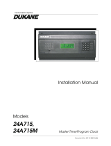
Thermal Considerations
The thermal design of this generator is for applications that
require 600 watts or less of power at less than a 50% duty
cycle. For applications that require higher duty cycles,
an optional cooling package is available. The cooling
package includes a heat sink that mounts to the rear of the
generator. See Section 5 - Options.
NOTE
Add transducer cooling as necessary to keep
front mass temperature to 100°F or less.
55%
60%
65%
75%
100%
50%
Duty Cycle
Standard Generators
Power
(Watts)
Duty Cycle
Generators with Optional Heatsink
Power
(Watts)
55%
60%
65%
75%
100%
100 200 300 400 500 600
50%
100 200 300 400 500 600
Figure 1-1 shows the thermal capability of the generator
with and without the cooling package. For further
information about the cooling package, contact your local
Dukane sales representative.
Figure 1–1 Thermal and Power Considerations for iQ Auto Generators

Page 6
iQ Series, Auto-Plus User’s Manual
Dukane Manual Part No. 403-591-00
This page intentionally left blank

Page 7
Section 2 – Health and Safety
Dukane Manual Part No. 403-591-00
SECTION 2
Health and Safety
General Considerations .............................. 9
Plastics Health Notice................................ 9
Electrical Safety ................................... 10
Power Grounding Connection ............................11

Page 8
iQ Series, Auto-Plus User’s Manual
Dukane Manual Part No. 403-591-00
This page intentionally left blank

Page 9
Section 2 – Health and Safety
Dukane Manual Part No. 403-591-00
Proper Installation - Operate system components only
after they are properly installed.
NoUnauthorizedModications- Do not modify your
system in any way unless authorized to do so by Dukane
Corporation. Unauthorized modications could cause
equipment damage and/or injury to the operator. In ad-
dition, unauthorized modications will void equipment
warranty.
Keep the Cover On - Do not remove any equipment
cover unless directed to do so by Dukane Corporation. The
generator produces hazardous electrical voltages which
could cause injury.
Grounded Electrical Power - Operate this equipment
only with a grounded electrical connection.
See Electrical Safety for grounding instructions, Page 9.
Comply with Regulations - You may be required to add
accessories to bring the system into compliance with
applicable regulations (OSHA in the USA) for machine
guarding and noise exposure.
Use Eye Protection - Wear ANSI approved safety impact
goggles.
Acoustic Stack Hazard - When an acoustic stack (trans-
ducer, booster, horn and tip) is energized by the ultrasound
signal, it presents a potential hazard. Stay clear of an
energized stack.
System E-STOP (abort) Switch - Install a system E-
STOP (abort) switch at each operator station when ultra-
sonic plastic assembly equipment is used with automatic
material handling equipment in an automated system.
Foot Switch - Do not use a foot switch. Using a foot
switch in place of the optical touch nger switches (oper-
ate switches) violates OSHA regulations. Do not install
a foot switch.
NOTE
These recommendations apply to the
welding system. System in this manual
refers to a complete group of components
associated with the welding of parts, also
known as an ultrasonic assembly system.
A typical iQ Series System consists of the
iQ generator, a press with thruster, switch-
es, controls, cables, transducer, booster,
horn, and xture, and iQ Explorer II software.
CAUTION
At some time you may be asked
to remove equipment covers
by the Dukane Service Dept.
personnel. Before doing so,
disconnect the unit electrically from the in-
coming line AC power. If the unit is a press/
thruster, lock the Air Lockout Valve, located
on the rear panel, in its closed position.
General Considerations
Please observe these health and safety recommenda-
tions for safe, efcient, and injury-free operation of your
equipment.
Never operate the genera-
tor with the cover off. This
is an unsafe practice and
may cause injury.
Any fixture manufactured
by a third party must com-
ply with all OSHA and ANSI
requirements. All xtures must
be guarded as necessary.
Dukane Corporation does not
assume any responsibility or li-
ability for xtures manufactured
by the customer or any third
party manufacturer.
WARNING
Continued
WARNING

Page 10
iQ Series, Auto-Plus User’s Manual
Dukane Manual Part No. 403-591-00
System Electrical Cabling - Electrical power must be
off when connecting or disconnecting electrical cables.
Do Not Wear Loose Clothing or Jewelry - They can
become caught in moving parts.
Stay Alert - Watch what you are doing at all times. Use
common sense. Do not operate the press when you are
tired or distracted from the job at hand.
Do Not Operate the Equipment - Your judgement or
reexes could be impaired while taking prescription medi-
cations. If so, do not operate the equipment. Be familiar
with warning labels and recommended activity restrictions
that accompany your prescription medications. If you have
any doubt, do not operate the equipment.
General Considerations
Plastics Health Notice
Certain plastic materials, when being processed, may
emit fumes and/or gases that may be hazardous to the
operator’s health. Proper ventilation of the work station
should be provided where such materials are processed.
Inquiries should be made to the U.S. Department of Labor
concerning OSHA regulations for a particular plastic prior
to processing with Dukane ultrasonic equipment.
Electrical Safety
The iQ Series generator provides the operating power
and power returns. Make sure the generator is grounded
properly.
In addition to the safety considerations, proper grounding
is essential for the effective suppression of RFI (Radio
Frequency Interference). Every generator contains a RFI
lter which blocks noise on the AC power line from enter-
ing the generator control circuitry. This lter also prevents
ultrasonic RFI from being fed back into the AC power line.
If you experience problems with RFI from the press, run
an additional grounding wire from the press base ground-
ing stud to the nearest grounded metal pipe or equivalent
earth ground by means of a ground clamp. Use at least 14
AWG wire for the connection to the press base.
Continued from Previous Page
WARNING
Keep head, hands, limbs
and body at least six
inches (152 mm) away
from an operating press/
thruster. A vibrating, descending horn
can cause burns and/or crushing
injuries.
CAUTION
CAUTION
Parts being joined ultrasoni-
cally will at times vibrate at
audible frequencies. Wear
ear protectors to reduce
annoying or uncomfort-
able sounds. In addition, ultrasound
bafes, sound enclosures, or materials
that absorb sound may be located to
surround the system. Ultrasound pres-
sure level could exceed 110dB. See
Ultrasonic Pressure, Table 8-II, Page 56.
When making cable connec-
tions to system equipment
or disconnecting cables
from system equipment,
make sure electrical power to the system
is turned off, and AC power cords are
removed from their receptacles. After the
cables have been securely connected
and the connections and cable routing
checked a nal time, the power may be
restored.

Page 11
Section 2 – Health and Safety
Dukane Manual Part No. 403-591-00
Electrical Safety
Power Grounding Connection
Figure 2-1 illustrates how the AC line is connected to the
iQ Auto Plus generator.
Figure 2–1 AC Line Connection
If there is any ques-
tion about grounding of
your equipment and/or its
electrical power source,
contact a qualified electrician.
Terminal
Wire Color
North America Europe
L (Live) Black Lt. Brown
(Ground) Green
Green w/yellow
stripe
N (Neutral) White Lt. Blue
Table 2-I Conventional Wire Color Code
L
N
iQ Auto Plus Power
Inlet
Pluggable AC
Line Connector
For safe system operation: To
avoid the risk of re, electri-
cal shock, serious injury or
death, the power line safety
ground must be securely
connected to the center terminal on
the (pluggable) AC line connector.
CAUTION
CAUTION

Page 12
iQ Series, Auto-Plus User’s Manual
Dukane Manual Part No. 403-591-00
This page intentionally left blank

Page 13
Section 3 – Installation
Dukane Manual Part No. 403-591-00
SECTION 3
Installation
Unpacking . . . . . . . . . . . . . . . . . . . . . . . . . . . . . . . . . . . . . . 15
Placement . . . . . . . . . . . . . . . . . . . . . . . . . . . . . . . . . . . . . . 15
Power Grounding . . . . . . . . . . . . . . . . . . . . . . . . . . . . . . . . . 16
Chassis Grounding Stud............................ 16
Connecting Cables ................................ 17
Basic Connections....................................17
P1 System I/O Connector Pinout.........................18
Multi-Probe Control (MPC) .............................20
MPC Module Installation Guide ...................... 22
MPC Module Status LEDs..............................24

Page 14
iQ Series, Auto-Plus User’s Manual
Dukane Manual Part No. 403-591-00
This page intentionally left blank
/