Page is loading ...

23x Indoor Speed Dome Camera
CAM-ISD48
User’s Manual
. .
User’s manual 1

CONTENTS
1. Safety Information..............................................................................4
2. Preface...............................................................................................5
3. Features.............................................................................................6
4. Appearance........................................................................................7
4.2 DIP switches................................................................8
4.3 Set Up Device ID Number ...........................................9
4.4 Control Protocol and Baud Rate................................12
4.5 RS-485 Network and Impedance...............................13
5. Mount The Speed Dome Camera....................................................16
5.1 Mounting Accessory...................................................17
5.2 Surface mount............................................................18
5.3 Embed Camera Into Ceiling.......................................19
5.4 Ceiling-drop mount (with CAM-CM)...........................20
5.5 Wall mount (with CAM-WM).......................................21
5.6 Use External Housing (with CAM-OH).......................23
6. Connecting Wires.............................................................................26
6.1 Power.........................................................................26
6.2 Video..........................................................................27
6.3 RS-485.......................................................................28
6.4 Alarm Input and Alarm Output ...................................28
7. Applications......................................................................................31
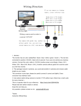
7.1 Controllers and RS-485.............................................31
7.2 Connect single dome to console................................32
7.3 Connect two or more domes to console....................35
8. Camera setup --- OSD functions .....................................................37
8.1 OSD operation...........................................................37
. .
User’s manual 2

8.2 OSD function List.......................................................37
8.3 OSD function description...........................................39
9. Pre-defined System Functions ........................................................45
10. Specification...................................................................................46
. .
User’s manual 3

1. Safety Information
Federal Communication Commission (FCC) Statement
CAUTION
This Class B digital apparatus meets all requirements of the
Canadian Interference Causing Equipment Regulations.
ATTENTION
Cet appareil numerique de laclasse B respects toutes les
exigencies du Reglement sur le materiel brouilleur du
Canada
NOTE: This equipment has been tested and found to comply
with the limits of a Class B digital device, pursuant to Part 15 of
the FCC Rules. These limits are designed to provide reasonable
protection against harmful interference when the equipment is
operated in a commercial environment. This device generates,
uses and can radiate radio frequency energy and, if not installed
and used in accordance with the instruction manual, may cause
harmful interference to radio communications. However, there is
no guarantee that interference will not occur in a particular
installation. If this equipment does cause harmful interference,
the user is encouraged to try to correct the interference by on or
more of the following measures:
Reorient or relocate the receiving antenna.
Increase the separation between the equipment and
receiver.
Correct the equipment into an output o a circuit different
from that to which the receiver is connected
Consult the dealer or an experienced radio / television
technician for help
FCC Caution: To assure continued compliance, any change
or modification not expressly approved by the
party responsible for compliance could void the
user’s authority to operate this equipment.
Notice for customers in Canada
. .
User’s manual 4

2. Preface
Congratulations for the purchasing of the world most compact PTZ (Pan, Tilt
and Zoom) camera. The camera is designed and manufactured not just to
meet the requirements for traditional CCTV and modern digital surveillance,
but also increase the systems’ overall performance.
This camera line incorporates high resolution color CCD, with two types of
lens available: power zoom or vari-focal. Some image and special effect
functions are related to the type of lens, while other functions are the same
across the line.
The PT mechanism provides controllable panning (360
o
) and tilting (90
o
)+
auto-rotation (180
o
) functions, giving users the capability to manipulate the
camera for precise locating on target. The built-in micro-controller allows users
to program up to 64 presets for quick and accurate capture to specific view
positions. Moving speed, ranging from 0.25 to 300 degrees per second and is
selectable to controller, is variable in 16 optional levels. Dwell time of each
view position is also selectable from 1second up to 255 seconds.
System function includes I/O for alarm function for intrusion management, ID
setup
(maximum to 128) and impedance matching option for multiple node
system, 3 control protocols, 3 options of baud rates, RS-485 communication
format. This device is driven by DC12V power. It can be controlled by
keyboard, PC, video server or standalone DVR.
For the power zoom version, a number of image related functions (such as
DSP functions, lens functions, special effects of video…) are managed via
OSD (On-Screen-Display) menu. These functions are explained in the section
of OSD with details. The CCD can be set up for automatic switching to
black-white mode for night-vision ready when illumination is low.
This camera is designed to be water-resistant for outdoor use, under the
condition of normal temperature range from -10
o
to 50
o
C. A companion
outdoor housing is also available for severe weather condition (extreme low or
high temperature environment).
. .
User’s manual 5

3. Features
High resolution color CCD 480 TV lines
23x optical / 10x digital zoom
Continuous panning for 360
o
; Tilt for 90
o
+auto-rotation (180
o
)
Fast rotation speed, up to 300
o
per second
RS-485 digital control, supporting multi-nude topology
BNC connector for video output
Programmable for view position, speed and dwell
View position preset, up to 64 points
Auto-pan and 4 groups of tour
3 alarm inputs and 1 alarm output
Compatible with Pelco D and Pelco P protocols
Internal ID setup function, maximum to 128
Compatible with keyboard and DVR for CCTV system
Compatible with PC and video server for WAN / LAN surveillance
For embedded, surface, wall and ceiling mount
External housing for severe outdoor environment (Option)
. .
User’s manual 6

4. Appearance
4.1 To Access DIP Switches
Before the camera is mounted in place, be sure the following four settings are
properly executed, or the camera may fail the control:
Camera ID setup
Protocol selection
Baud rate selection
Termination impedance
Tools:
Use pencil, pincer, paper clip or small flat screw driver, to move the lever of DIP
switch
Access points:
The DIP switches are located on the bottom of the dome cameras:
DIP switches
. .
User’s manual 7

4.2 DIP switches
Overview of DIP switches
There are three sets of DIP switch on board for different setup purposes.
location # bit quantity used for
DS1 8 Protocol / baud rate setup
DS2 8 Device ID setup
DS3 2 Network impedance
Refer to the picture on below for DIP switch locations.
DS3 DS1 DS2
In the following paragraphs are the detail descriptions of the three main setups the
installer must do, before hardware mounting and cabling work should begin.
. .
User’s manual 8

4.3 Set Up Device ID Number
To build correct network for control communication, every speed dome camera in
the network must have an unique ID number
, which is set by the bit 1 to 8 of a
8-bit DIP switch DS2.
Note: Factory default of device ID is 1
Find 8-bit DIP switch DS2 on the PC board
DS2
Bit number
remark: Dash line “---“ in table means to
set the bit to “OFF” position
Refer to the tables in the next two pages for ID setting (the tables will show the
relation between pin assignments of DIP switch and ID numbers 1 to 128)
Since the highest ID of this camera is 128, maintain the bit number 8 in OFF
position all the time.
All the speed domes in a network must have their unique ID. It is highly
recommended to installers, for future maintenance and users’ convenience, to
mark the ID of each camera onto its corresponding location on the site map,
and make out a list of cameras with their ID numbers.
The DS2 pin assignment for ID setup is in binary format.
. .
User’s manual 9

ID table (1 ~ 64)
. .
User’s manual 10

ID table (65 ~ 128)
. .
User’s manual 11

4.4 Control Protocol and Baud Rate
Control protocol and baud rate must be set correctly in the dome camera in order to
establish proper control communication between the camera and control device.
Be sure that the same protocol and baud rate must be implemented in control
device, too.
3 types of protocol and 3 levels of baud rate are provided by this speed dome,
through an 8-bit DIP switch labeled DS1.
. .
User’s manual 12
First, installer needs to choose a communication protocol with bit number 3, 4
and 5. Watch that the same protocol is chosen for speed dome and controller.
The following table shows the three protocols provided in this speed dome.
Check what are available in the controller before choosing the protocol.
3 4 5
Protocol
-- -- --
Pelco-D
on -- --
Pelco-P
-- on --
Reserved
on on --
Reserved
Bit 1 and 2 are for baud rate setup. Same baud rate must be set up for the
speed dome and control device, or communication fro control will fail.
1 2 Baud rate
-- --
2,400 bps
on --
4,800 bps
-- on
9,600 bps
DS 1
remark:
1. “--“ means to set the bit to “OFF” position
2. Bit 1 and 2 are for baud rate setup
3. Bit 3, 4 and 5 are for protocol selection
4. Bit 6 is reserved future use
5. Bit 7 is for firmware upgrade
6. Bit 8 is for cooling fan on / off switching

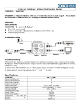
4.5 RS-485 Network and Impedance
Transmission distances of RS-485 Bus
The 0.56mm (24AWG) twisted pair or higher grade wires are recommended for data
transmission cable.
The maximum theoretical transmitting distances, for the AWG#24, are as follows:
Baud Rate Maximum Transmitting Distance
2400 Bps 1800m
4800 Bps 1200m
9600Bps 800m
If user selects thinner cables, or installs the dome in an environment with strong
electromagnetic interference, or connects lots of equipment to the RS-485 bus, the
maximum transmitting distance will be decreased. To increase the maximum
transmitting distance, do the contrary, i.e. use thicker wire and keep the cable away
from the interference.
Connection and termination resistor
The RS-485 standard requires a daisy-chain connection among the equipments.
There must be termination resistors of proper impedance (typically 120 ohms,
within the range from 90 to 250 ohms) at both ends of the connection.
120Ω 120Ω
1# 2# 3# 4# 32#
. . . . .
120Ω
1# 2# 3# 31#
120Ω
D
A+
B-
A+ B -
.....
.....
Main controller
. .
User’s manual 13

Impedance setup for the speed dome
Each speed dome camera has a termination resistor built in.
In a network of RS-485 chain, the speed domes are classified in two categories:
end unit (such as the #31) and node (such as #1 through #30).
To set up the resistor correctly, installer must decide if the specific dome camera is
the termination device or not, i.e. if it is at the end of the RS-485 chain.
The impedance setup is provided by the bit 1 and bit 2 of DIP switch
DS3 .
DS3
Bit 1
Bit 2
Impedance
-- --
Open ( device on node )
On On
Standard 120 ohms ( device at end )
For nodes: Set both of Bit 1 and Bit 2 to OFF position
For end unit: Set both of Bit 1 and Bit 2 to ON position
Impedance of the control unit
This is generally for two cases: controller with RS-485, and controller with RS-232.
Controller with RS-485:
Most keyboard and video server in market have RS-485, which are equipped with
termination resistor to drive a RS-485 system.
But most PC and notebook sort of devices have RS-232 or USB port but no RS-485.
Therefore, for PC system, a RS-232 or USB to RS-485 converter is required. So
installer must check out if the converter has proper termination resistor.
Problems in practical connection
. .
User’s manual 14
In some circumstances user adopts a star configuration in practical connection. The
termination resistors must be connected to the two equipment that are farthest
away from each other, such as equipment 1# and 15# in the following picture. As
the star configuration is not in conformity with the requirements of RS-485

standards, problems such as signal reflections, lower anti-interference performance
arise when the cables are long in the connection. The reliability of control signals
could be downgraded with the phenomena that the dome does not respond to or
just responds at intervals to the controller, or does continuous operation without
stop
In such circumstances the usage of RS-485 distributor is recommended. The
distributor can change the star configuration connection to the mode of connection
stipulated in the RS-485 standards. The new connection achieves reliable data
transmission.
RS
-
485
di
s
t
r
ib
u
t
o
r
. .
User’s manual 15

5. Mount The Speed Dome Camera
The camera and its mounting system are designed in modules. There are 5
methods to mount the PTZ camera, which are:
1. Attached to the ceiling surface directly
2. Embedded into ceiling
3. Held to ceiling surface through a bracket (ceiling-drop)
4. Mounted to wall through a bracket
5. Adapted into external housing
For all these five mounting ways, a common mounting base for mechanical locking
and signal interface shall be adapted as below.
In the next page there is a list of all the accessories provided with the camera for
various environments.
. .
User’s manual 16

5.1 Mounting Accessory
The following items are supplied with the speed dome for the camera mounting.
Description The look The Use
1
Plastic ring
To hold the camera
mbedded on ceiling e
Must be used with the
metal ring together to
hold the PTZ camera..
2
Metal ring
To hold the camera
mbedded on ceiling e
Must be used with the
plastic decoration ring
together to hold the PTZ
camera.
3
Mounting base
The interface for holding
the camera and bridging
signals
4
Plastic Housing
for surface
mount
To hold the camera on
ceiling surface
5
Metal Bowl
holder
To work with item 3 for
creating ceiling or wall
mount
. .
User’s manual 17

5.2 Surface mount
1.
Before installation starts, put mounting base and plastic housing together to
make a base module
2.
Locate the base module onto the place the camera is to be mounted, and fix
the base on the surface completely with screws through the 3 holes on the
base (be sure the cables are well located throughout the cable outlet)
3.
Get the camera and plug it onto the base; watch for the direction of the
connectors on camera and mounting base and be sure they are mated well.
Then rotate the camera body counter-clockwise until it is completely locked
4. Put the safety screw (anti-loss) in locking position and screw it in
. .
User’s manual 18
In case of dealing with a concrete surface:
a. Mark the locations for screw through the holes on the base
b. Make holes on the wall, then insert the supplied plastic plugs into the holes and
squeeze them in until they are flush with the wall surface.
c. Mount the base on the desired place tightly with screws
Integrate the mounting base and the
plastic housing as a module
Mounting the module to the surface
Fit the camera into the module and
lock it in position
Put the safety screw in place

5.3 Embed Camera Into Ceiling
Step 1 make holes
To insert the speed dome into the ceiling, first
a hole must be properly made to let the dome
be through for hanging.
The best way to decide the diameter of the
hole, and the spots for mounting screws, is to
use the supplied metal holder.
Put the holder on the surface of the target location and mark a circle with
pencil or color marker
Also mark out the spots for screws with the screw holes on the holder
Cut the camera hole alone with the curve
Drill holes for screw in 6 mm (1/4”) on the three marked spots;
Step 2 Integrate the decoration ring with camera
The decoration ring is not just for nice looking,
but also the piece to hold the camera in place
for embedded mounting.
To integrate the ring to camera:
1. Take the transparent dome cover off
2. Locate the ring to the bottom side of the
cover
3. Put the cover back to the camera
Step 3 Mount the camera through the hole
Take the below steps to make the camera cling
to ceiling:
1. Place the auxiliary metal bracket onto the
top of the ceiling
2. Put the camera through out the hole
3. Align the screw holes of the decoration
ring and the auxiliary bracket
4. Put screws through and tighten the two
brackets, with the ceiling in between
. .
User’s manual 19

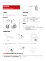
5.4 Ceiling-drop mount (with CAM-CM)
Pre-assembling of the Bowl Module
Both ceiling-drop and wall-mount needs to have a bowl module, an assembly of the
mounting base and metal bowl supplied in the mounting kit, be built first.
Follow the flow chart on below for building up the bowl module.
Put the base
into the bowl
Make a
module
The mounting base
The bowl module
Metal bowl
To drop camera from ceiling, take the ceiling bracket (option item) and bowl module,
1. put the cables into the tube and have them come out from cable outlet
2. put the bracket on top of the bowl and tight them together with screws
The bowl module
Put the bowl
on bracket
Make an
assembly
3. Locate the assembled piece onto the place the camera is
to be mounted, and fix it on the surface completely with
screws through the 3 holes on the bracket
4.
Get the camera and plug it onto the base; watch for the
direction of the connectors on camera and mounting base
and be sure they are mated well. Then rotate the camera
body counter-clockwise until it is completely locked
5. Put the safety screw (anti-loss) in locking position and
screw it in
. .
User’s manual 20
/