Page is loading ...

1
User’s Manual
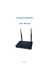
11N ADSL2+ Modem Router
Model No.: SP3367NL

2
Table of Contents
1. Introduction.....................................................................................................2
1.1 Package Contents......................................................................................................................... 2
1.2 Key Features................................................................................................................................. 2
1.3 Safety Information......................................................................................................................... 3
2. Physical Description .......................................................................................5
2.1 Back Panel.................................................................................................................................... 5
2.2 Front Panel ................................................................................................................................... 6
2.3 Hardware Connection ................................................................................................................... 7
3. System and Network Setup............................................................................8
3.1 Build Network Connection ............................................................................................................ 8
3.2 Connecting to Web-Based Management...................................................................................... 9
3.3 Router’ s IP Address ................................................................................................................. 13
4. Web-Based Management UI ........................................................................16
4.1 Fast internet access.................................................................................................................... 16
4.2 Wireless ...................................................................................................................................... 20
4.3 Advanced Setup.......................................................................................................................... 28
5. Management ................................................................................................70
5.1 System log .................................................................................................................................. 70
5.2 SNMP Agent ............................................................................................................................... 71
5.3 TR-069 client............................................................................................................................... 72
5.4 Internet Time............................................................................................................................... 74
5.5 Access Control............................................................................................................................ 75
5.6 Backup ........................................................................................................................................ 76
5.7 Update ........................................................................................................................................ 77
5.8 Restore default............................................................................................................................ 77
5.9 Update Software ......................................................................................................................... 79
5.10 Reboot ........................................................................................................................................ 79

1
Certifications
FCC
This equipment has been tested and found to comply with Part 15 of the FCC Rules.
Operation is subject to the following two conditions:
(1) This device may not cause harmful interference
(2) This device must accept any interference received. Include interference that may cause
undesired operation.
CE
This equipment is in compliance with the requirements of the following regulations: EN 55
022: CLASS B.
RoHS
All contents of this package, including products, packing materials and documentation
comply with RoHS.

2
1. Introduction
Micronet SP3367NL/SP3367NE, 11N ADSL2+ Modem Router, delivers highly reliable and
scalable network environment. The model has incorporated both modem and router
functions into a single unit with wireless support. It is compliant with IEEE 802.11 N and
backward compatible with IEEE 802.11b/g. The wireless connection can be optimized up
to high-speed data rate of 300Mbps for multimedia applications. The modem router allows
multiple network devices to share the single Internet connection via ADSL. Sustain
network security via router’s in-built firewall and DMZ functions.
1.1 Package Contents
Prior to the installation of the device, please verify the following items are in the
package:
1 x 11N ADSL2+ Modem Router
1 x Quick Installation Guide
1 x Product CD
1 x Voice Splitter
1 x Power Adapter
1.2 Key Features
ADSL2/2+ Compliance
Support downstream rates of up to 24Mbps and upstream rates of up to
1Mbps.
Compliant to ITU-T G.992.1 (G.dmt), G.992.2 (G.lite), G.992.3 (ADSL2),
G.992.4 (splitterless ADSL2), G.992.5 (ADSL2+) for Annex A, B. (Annex A
and B are supported in different H/W platform)
Supports Multi-Mode standard (ANSI T1.413, Issue 2; G.dmt (G.992.1);
G.994.1 and G.996.1 (for ISDN only); G.991.1;G.lite (G992.2)).
Multiple Protocols over AAL5 (RFC 1483/2684).
PPP over AAL5 (RFC 2364).

3
PPP over Ethernet (RFC 2516).
Support 802.11n Wireless Access Point
Complies with IEEE 802.11n, IEEE 802.11g and IEEE 802.11b standards.
Farther coverage, less dead spaces and higher throughput with MIMO
technology.
High data rate – up to 300Mbps network speed.
Supports 64-bit/128-bit WEP, WPA-PSK and WPA2-PSK wireless security
functions.
Supports WPS (WiFi Protected Setup) to easy connect wireless network
without configuring the security.
Support Auto Channel Selection.
Supports MAC address filtering.
Supports WDS
Router Advance Functions
NAT (Network Address Translation) IP Sharing
Virtual Server
DMZ
SPI Anti-DOS Firewall
DHCP Server and Client
ACL (Access Control)
IP/MAC/Application/URL Filter
UPnP (Universal Plug and Play)
Dynamic DNS
1.3 Safety Information
In order to keep the safety of users, please follow the following safety instructions:
This router is designed for indoor use only.
Do not put this router at or near hot or humid places. Also, do not leave this router
in the car in summer.
Do not pull any connected cable with force and disconnect it from the router.

4
If users want to place this router at high places, please make sure the router is
firmly secured. Falling from high places would damage the router and its
accessories, and in such cases, the warranty will be void.
Accessories of this router, like antenna and power supply, are danger to small
children under 3 years old. They may put the small parts in their nose or month
and it could cause serious damage to them.
The router will become hot when being used for long time (This is normal and is
not a malfunction). Do not put this router on paper, cloth or other flammable
materials.
There’s no user-serviceable part inside the router. If users found the router is not
working properly, please contact the authorized dealer of purchase. Do not
disassemble the router, otherwise warranty will be void.
If the router falls into water when it’s powered on, do not use hands to pick it up.
Switch the electrical power off before doing anything, or contact an experienced
technician for help.
If users smell something strange, or even see some smoke coming out from the
router or power supply, remove the power supply or switch the electrical power off
immediately, and call authorized for help.

5
2. Physical Description
2.1 Back Panel
Parameter Description
ON/OFF
Power Switch. Press it in to turn on the power and
press it out to turn off the power.
WPS/Reset
Hold and press it for 1 seconds to connect WPS,
and 7 seconds to bring all settings back to factory
defaults.
Power
Jack
Please plug the power adapter attached with the
ADSL Router to the power jack. The power adapter
is 9VDC, 1A.
LAN
LAN network cable interface. It is used to connect
Hub, Switch, or computer in a LAN.
(LAN2 port can also be used to connect IPTV Set-
top box to enable watching TV and online surfing at
the same time. When the access way is changed
into community broadband, LAN4 can be used as
the wireless Router’s WAN port.)
ADSL
Connect the supplied RJ-11 telephone line to this
port and your ADSL/telephone network.

6
Note:
Please use the supplied power adapter, for use of an unmatched power adapter may
damage the device.
2.2 Front Panel
LED Color Status Description
Always On The device has power
Power Green
OFF
The device has no power or power adapter is
damaged
Always On Connected to Internet
SYS Green
Flashing Packets are being transferred through ADSL Link
Flashing Packets are being transferred
WLAN Green
Off Wireless is disabled
Slow
Flashing
ADSL Link has not been established
Fast
Flashing
ADSL Link is being established
ADSL Green
Always On ADSL Link has already been established
Off Unconnected LAN
1/2/3/4
Green
Flashing Packets are being transferred

7
Always On The router has been connected to the computer
ON
Terminal WPS is successfully connected and the
LED lights off in 5 minutes
Flashing WLAN terminal is connecting WPS
WPS Green
Off
No WLAN terminal WPS connection is present or
terminal WPS connection exceeds 5 minutes
2.3 Hardware Connection
Follow the diagram below to connect your network devices when using DSL uplink access
mode (through telephone line).

8
3. System and Network Setup
3.1 Build Network Connection
Please follow the following instruction to build the network connection between the new
wireless router and other network computers and devices:
1. Connect the ADSL port of modem router by telephone cable (RJ-11) to an outlet
or splitter.
2. Connect all computers, network devices (network-enabled consumer devices
other than computers, like game console, or switch / hub) to the LAN port of the
router.

9
3. Connect the A/C power adapter to the wall socket, and then connect it to the
‘Power’ socket of the router.
4. The ADSL LED will be ON if the router is connected to the ADSL cable and
receives the ADSL signals successfully. If the LED is blinking, please contact with
your ISP (Internet Service Provider) to check the problem.
3.2 Connecting to Web-Based Management
After the network connection is established, the next step is to setup the router with
proper network parameters for the user’s network environment.
Before connecting to the router and start configuration procedures, user’s computer
must be able to get an IP address automatically (use dynamic IP address). If the PC is
set to ‘static IP address’, then follow instructions below to reconfigure it to ‘dynamic IP
address’.
IP Address Configuration
a) Windows 95/98/Me
1. Click the Start button and select <Settings>, then click <Control Panel>. The
Control Panel window will appear.
2. Double-click on <Network> icon. The Network window will appear.

10
3. Check the list of Network Components. If TCP/IP is not installed, click the
<Add> button to install it. If TCP/IP is installed, go to step 6.
4. In the Network Component Type dialog box, select <Protocol> and click <Add>
button.
5. In the Select Network Protocol dialog box, select <Microsoft> and <TCP/IP>
then click the <OK> button to start installing the TCP/IP protocol. Windows CD
may be needed to complete the installation.
6. After installing TCP/IP, go back to the Network dialog box. Select <TCP/IP>
from the list of Network Components and then click the <Properties> button.
7. Check each of the tabs and verify the following settings:
Bindings: Check Client for Microsoft Networks and File and printer sharing
for Microsoft Networks.
Gateway: All fields are blank.
DNS Configuration: Select Disable DNS.
WINS Configuration: Select Disable WINS Resolution.
IP Address: Select Obtain IP address automatically.
8. Reboot the PC. PC will now obtain an IP address automatically from the
Broadband Router’s DHCP server.
9. Please make sure that the Broadband router’s DHCP server is the only DHCP
server available on the LAN network.
10. Proceed to Web-based User Interface once IP address is correctly configured.

11
b) Windows 2000
1. Click the <Start> button and select <Settings>, then click <Control Panel>.
The Control Panel window will appear.
2. Double-click <Network and Dial-up Connections> icon. In the Network and
Dial-up Connection window, double-click on <Local Area Connection> icon.
The Local Area Connection window will appear.
3. In the Local Area Connection window, click the <Properties> button.
4. Check the list of Network Components. Users should see Internet Protocol
[TCP/IP] on the list. Select it and click the <Properties> button.
5. In the Internet Protocol (TCP/IP) Properties window, select <Obtain an IP
address automatically> and <Obtain DNS server address automatically> as
shown on the following screen.
6. Click <OK> to confirm the setting. The PC will now obtain an IP address
automatically from the Broadband Router’s DHCP server.
7. Please make sure that the Broadband router’s DHCP server is the only DHCP
server available on the LAN network.
8. Proceed to Web-based User Interface once IP address is correctly configured.
c) Windows XP
1. Click the <Start> button and select <Settings>, then click <Network
Connections>. The Network connections window will appear.

12
2. Double-click <Local Area Connection> icon. The Local Area Connection
window will appear.
3. Check the list of Network Components. Users should see Internet Protocol
[TCP/IP] on the list. Select it and click the <Properties> button.
4. In the Internet Protocol (TCP/IP) Properties window, select <Obtain an IP
address automatically> and <Obtain DNS server address automatically> as
shown on the following screen.
5. Click <OK> to confirm the setting. PC will now obtain an IP address
automatically from the Broadband Router’s DHCP server.
6. Please make sure that the Broadband router’s DHCP server is the only DHCP
server available on the LAN network.
d) Windows Vista
1. Click <Start> button, then click control panel. Click <View Network Status and
Tasks>, then click <Manage Network Connections>. Right-click <Local Area
Network>, then select <Properties>. Local Area Connection Properties window
will appear, select <Internet Protocol Version 4 (TCP / IPv4)> and click
<Properties>.

13
2. Select <Obtain an IP address automatically> and <Obtain DNS server
address automatically>, then click <OK>.
3.3 Router’s IP Address
1. After the IP address setup is complete, please click <Start> then <Run> at the
bottom lower corner of the desktop.

14
2. Enter ‘cmd’ command and click <OK>.
3. Input ‘ipconfig’, then press ‘Enter’ key. Please check the IP address followed by
‘Default Gateway’ (In this example, the IP address of router is 192.168.1.1, please
note that this value may be different).

15

16
4. Web-Based Management UI
4.1 Fast internet access
In previous section, we have explained how to log on to the router and in the following; we
are going to illustrate how to configure the router quickly to let your PC access Internet.
Now check whether you have the screen below, if not, please re-log on to the router’ s
management interface.

17
Have you noticed the option of “ Network” ----“ Access Mode” . There are two modes
available:
DSL Uplink: Select this mode, if you are using a telephone line to directly connect to
router’ s DSL port and then connect the router to your PC (Internet---telephone line—
router---network cable---PC).
Ethernet Uplink: Select this mode, if you are using a network cable to directly connect to
router and then connect the router to your PC (Internet---network cable—router---network
cable---PC).
Diagram of DSL Uplink mode (Internet access through telephone line) is shown below:
For Internet access via DSL uplink mode (through telephone line), there are 4 options
available under “ Network” : 1. Country, 2. Area, 3. PPPOE User name, 4. PPPOE
Password.

18
Country: Select your country.
Area:This option is mainly for distinguishing various areas and operators that have
different VPI/VCI values. To make it convenient for its users, this device has integrated
some main VPI/VCI values. You only need to select your area and operator and the router
will automatically offer a correspondingly matched VPI/VCI value of your local area.
PPPOE User name: the user name provided by your ISP; used together with password to
authenticate the user.
PPPOE Password: the password provided by your ISP; used together with user name to
authenticate the user.
For example: User A obtains a user name and a pass word, which are respectively
ADSL broadband, so he/she needs to input the parameters as below:
Note: For the sake of security, password input on Web UI is shown in encryption code.
Wireless function is supported by this product, so you still have to configure wireless
parameters. Please read the following:
Easy-to-install-----Wireless network configuration (as shown below)
/