
FPI FIREPLACE PRODUCTS INTERNATIONAL LTD. 6988 Venture St., Delta, BC Canada, V4G 1H4
WARNING:
If the information in these instructions are not followed exactly,
a fire or explosion may result causing property damage,
personal injury or loss of life.
FOR YOUR SAFETY
Do not store or use gasoline or other flammable vapors and
liquids in the vicinity of this or any other appliance.
Installation and service must be performed by a qualified
installer, service agency or the gas supplier.
FOR YOUR SAFETY
What to do if you smell gas:
Do not try to light any appliance
Do not touch any electrical switch:
do not use any phone in your
building.
Immediately call your gas supplier
from a neighbour's phone. Follow
the gas supplier's instructions.
If you cannot reach your gas
supplier, call the fire department.
908-788a 01/09/06
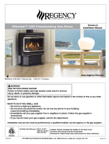
TARA Direct Vent Freestanding Gas Stove
Owners &
Installation Manual
MODELS: T25-NG Natural Gas T25-LP Propane
www.waterfordstoves.com
Tested by:
Installer: Please complete the details on the back cover
and leave this manual with the homeowner.
Homeowner: Please keep these instructions for future reference.

2
Waterford TARA T25 Direct Vent Freestanding Gas Stove
WATERFORD
TARA Direct Vent Freestanding Gas Stove
To the New Owner:
Congratulations! You are the owner of a state-of-the-art Waterford Direct Vent Freestanding Gas Stove
by Waterford Irish Stoves. The Waterford Gas Series of hand crafted appliances has been designed
to provide you with all the warmth and charm of a woodstove, at the flick of a switch. The TARA has been
approved by Warnock Hersey for both safety and efficiency. As it also bears our own mark, it promises
to provide you with economy, comfort and security for many trouble free years to follow. Please take a
moment now to acquaint yourself with these instructions and the many features of your TARA Direct Vent
Freestanding Gas Stove.
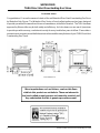
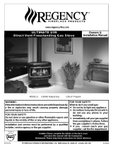
Tara Dimensions
Minor imperfections such as blisters, seeds or thin flaws
visible in this product are not defects. These are inherent in
the hand-crafted enamel process and cannot be avoided, and
they substantiate that this is genuine porcelain enamel.

Waterford TARA T25 Direct Vent Freestanding Gas Stove
3
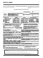
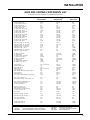
TABLE OF CONTENTS
Converting a Factory Built Metal Chimney .............. 22
High Elevation...................................................... 23
System Data Chart .............................................. 24
Gas Connection ................................................... 24
Gas Pipe Pressure Testing ................................... 24
Valve Description ................................................. 24
Valve Conversion to Propane ................................. 24
Aeration Adjustment ............................................. 26
Removing Cast Iron Front Panel ............................ 26
Optional Front Grill ............................................... 26
Optional Side Shelf .............................................. 27
Log Installation .................................................... 27
Optional Wall Thermostat ..................................... 27
Optional Remote Control Installation ...................... 28
Final Check ......................................................... 28
Wiring Diagram .................................................... 28
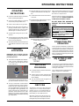
Operating Instructions
Operating Instructions .......................................... 29
Lighting Procedure ............................................... 29
Shutdown Procedure ............................................ 29
First Fire ............................................................. 29
Convection Fan Operation ..................................... 29
Adjusting Flame Height ........................................ 29
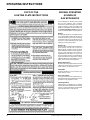
Copy of Lighting Plate Instructions ......................... 30
Normal Operating Sounds of Gas Appliances ......... 30
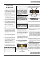
Maintenance
Maintenance Instructions ...................................... 31
General Vent Maintenance.................................... 31
Log Replacement ................................................. 31
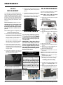
Glass Replacement .............................................. 32
Fan Maintenance ................................................. 32
Valve Maintenance............................................... 32
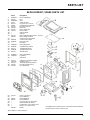
Replacement Parts List ........................................ 33
Warranty
Warranty ............................................................. 35
Page
Safety Label
Safety Labels ........................................................4
Installation
Information for Mobile/Manufactured Home
After First Sale ...................................................5
Before You Start ....................................................5
Manufactured Mobile Home
Requirements .....................................................6
General Safety Information ......................................6
Installation Checklist ..............................................6
Clearances to Combustibles ...................................6
Locating Your TARA Gas Stove ...............................7
Optional Fan Installation .........................................7
Venting Introduction ...............................................9
Installation Precautions ..........................................9
Safety Precautions for the Installer ..........................9
Combustion and Ventilation Air ...............................9
Exterior Vent Terminal Locations ........................... 10
Minimum Horizontal Termination............................ 11
Vertical Termination with Co-Linear Flex System .... 13
DV Stove Horizontal Vent Kit and Installation.......... 14
Dura-Vent Termination Kits ................................... 15
Minimum Dura-Vent Components - Horizontal
Installation........................................................ 16
Minimum Dura-Vent Components - Vertical
Termination ...................................................... 16
Rigid Pipe Venting Components List ...................... 17
Rigid Pipe Venting
- Dura-Vent Horizontal Installation....................... 18
- Dura-Vent Vertical Termination Installation ........ 18
Vent Restrictor .................................................... 19
Dura-Vent Horizontal Installation............................ 19
Dura-Vent Vertical Installation ............................... 20
Offset Chart ......................................................... 21
Cathedral Ceiling Installations ............................... 21
Support Extension - Round or Square .................... 21
Converting a Class-A Metal Chimney or Masonry
Chimney to a Direct Vent System ...................... 21
Page

4
Waterford TARA T25 Direct Vent Freestanding Gas Stove
This is a copy of the label that accompanies
each TARA Direct Vent Freestanding Gas
Stove. We have printed a copy of the contents
SAFETY LABEL
here for your review. The safety label is located
on the inside of the drop down pedestal door.
Copy of Safety Label for TARA T25 Gas Stove
NOTE: Waterford units are constantly being
improved. Check the label on the unit and if
there is a difference, the label on the unit is the
correct one.
For the State of Massachusetts, installation and repair must be done by a plumber or gasfitter licensed in the Commonwealth of
Massachusetts.
For the State of Massachusetts, flexible connectors shall not exceed 36 inches in length.
For the State of Massachusetts, the appliances individual manual shut-off must be a t-handle type valve.

Waterford TARA T25 Direct Vent Freestanding Gas Stove
5
IMPORTANT:
SAVE THESE
INSTRUCTIONS
The TARA Direct Vent Freestanding Gas Stove
must be installed in accordance with these
instructions. Carefully read all the instructions
in this manual first. Consult the building author-
ity having jurisdiction to determine the need for
a permit prior to starting the installation.
Note: Failure to follow the instructions
could cause a malfunction of the
heater which could result in death,
serious bodily injury, and/or prop-
erty damage. Failure to follow
these instructions may also void
your fire insurance and/or war-
ranty.
Note: These instructions take prece-
dence over Simpson Dura-Vent
instructions.
SPECIFICATIONS
Fuels: The TARA is factory equipped for
use with natural gas. A Propane
Conversion Kit (#290-969) is availa-
ble to convert the TARA for use with
liquefied petroleum gases (propane).
Electrical: 120V A.C. system.
Circulation Fan: Variable speed, 125/75
(Optional)
Log Sets: Ceramic fibre, 5 per set.
Vent System: Coaxial (6-5/8" outer / 4"
inner liner) rigid flue and
termination cap.
The efficiency rating of the appliance is a
product thermal efficiency rating determined
under continuous operating conditions and
was determined independent of any installed
system.
INFORMATION FOR
MOBILE/
MANUFACTURED
HOMES AFTER
FIRST SALE
This Waterford product has been tested and
listed by Warnock Hersey as a Direct Vent Wall
Furnace to the following standards: UL 307B-
1995, CAN/CGA-2.17-M91 and ANSI Z21.88b-
2003/CSA 2.33b-2003.
INSTALLATION
This Direct Vent System Appliance must be
installed in accordance with the manufactur-
er's installation instructions and the Manufac-
tured Home Construction and Safety Standard,
Title 24 CFR, Part 3280, or the current Standard
of Fire Safety Criteria for Manufactured Home
Installations, Sites, and Communities ANSI/ NFPA
501A, and with CAN/CSA Z240-MH Mobile
Home Standard in Canada.
This appliance installation must comply with the
manufacturer's installation instructions and local
codes, if any. In the absence of local codes
follow the current National Fuel Gas Code,
ANSI Z223.1 and the current National Electrical
Code ANSI/NFPA 70 in the U.S.A., and the
current CAN/CGA B149 Gas Installation Code
and the current Canadian Electrical Code CSA
C22.1 in Canada.
INSTALLATION AND REPAIRS
SHOULD BE DONE BY A QUALIFIED
SERVICE PERSON. THIS APPLI-
ANCE SHOULD BE INSTALLED,
REPAIRED, INSPECTED BEFORE
USE AND AT LEAST ANNUALLY BY
A QUALIFIED SERVICE PERSON.
MORE FREQUENT CLEANING MAY
BE REQUIRED DUE TO EXCESSIVE
LINT FROM CARPETING, ETC. IT IS
IMPERATIVE THAT THE CONTROL
COMPARTMENT, BURNERS AND
CIRCULATING AIR PASSAGEWAYS
BEFORE YOU START
Safe installation and operation of this appliance
requires common sense, however, we are
required by the Canadian Safety Standards and
ANSI Standards to make you aware of the
following:
1) Provide adequate clearances for servicing,
proper operation and around the air open-
ings into the combustion chamber.
2) The appliance must be installed on a flat,
solid, continuous surface (e.g. wood, metal,
concrete). This may be the floor, or it can be
raised up on a platform to enhance its visual
impact. The appliance may be installed on
carpeting, tile, wood flooring or other com-
bustible material. The TARA Direct Vent
Freestanding Gas Stove can be installed in
a wide variety of ways and will fit nearly any
room layout. It may be installed in a recessed
position, framed out into the room, or across
a corner.
3) The TARA Direct Vent Freestanding Gas
Stove is approved for alcove installations,
which meet the clearances listed on page 6.
This unit is approved for manufactured home
installations, see page 6 and pages 9 to 17
for the required vent arrangements. If in-
stalled into a manufactured home the unit
must be bolted down to the floor.
4) This appliance is Listed for bedroom instal-
lations when used with a Listed Millivolt
This Waterford Mobile/Manufactured
Home Listed appliance comes factory
equipped with a means to secure the
unit.
This Waterford Mobile/Manufactured
Home listed appliance comes equipped
with a dedicated #8 ground lug to which
an 18 gauge copper wire from the steel
chassis ground must be attached.
This appliance may only be installed in
an aftermarket permanently located,
manufactured (mobile) home, where
not prohibited by local codes.
This appliance is only to be used with
the type of gas indicated on the rating
plate. This appliance is not convertible
for use with other gases, unless a cer-
tified kit is used.
OF THE APPLIANCE BE KEPT
CLEAN.
DUE TO HIGH TEMPERATURES,
THE APPLIANCE SHOULD BE LO-
CATED OUT OF TRAFFIC AND
AWAY FROM FURNITURE AND
DRAPERIES.
WARNING: FAILURE TO INSTALL
THIS APPLIANCE CORRECTLY
WILL VOID YOUR WARRANTY AND
MAY CAUSE A SERIOUS HOUSE
FIRE.
CHILDREN AND ADULTS SHOULD
BE ALERTED TO THE HAZARDS
OF HIGH SURFACE TEMPERA-
TURES, ESPECIALLY THE FIRE-
PLACE GLASS, AND SHOULD
STAY AWAY TO AVOID BURNS
OR CLOTHING IGNITION.
YOUNG CHILDREN SHOULD BE
CAREFULLY SUPERVISED WHEN
THEY ARE IN THE SAME ROOM AS
THE APPLIANCE.
CLOTHING OR OTHER FLAMMA-
BLE MATERIAL SHOULD NOT BE
PLACED ON OR NEAR THE APPLI-
ANCE.

6
Waterford TARA T25 Direct Vent Freestanding Gas Stove
specified vent and termination cap to the
outside of the building envelope. Never vent
to another room or inside a building. Make
sure that the vent is fitted as per the instruc-
tions starting on page 9.
6) Inspect the venting system annually for
blockage and any signs of deterioration.
7) Venting terminals shall not be recessed into
a wall or siding.
8) Any safety glass removed for servicing
must be replaced prior to operating the
appliance.
9) To prevent injury, do not allow anyone who
is unfamiliar with the operation to use the
fireplace.
INSTALLATION
CHECKLIST
1) Check Clearances to Combustibles (page
6), location of unit (page 7) and venting
requirements (pages 9-20).
2) a) Carefully unpack the unit from the pack-
aging.
EXTREME CARE NEEDS TO BE
TAKEN WHEN HANDLING POR-
CELAIN ENAMEL PARTS OR
CERAMIC LOGS TO AVOID
DAMAGE. DAMAGE TO THESE
PARTS IS NOT COVERED UN-
DER WARRANTY.
b) Use a 7/16" wrench to remove the two
lag bolts used to secure the stove to the
pallet.
c) Locate the 4 leg levelling bolts supplied
with the stove. Fit these bolts to the
underside of the legs as shown. These
levelling bolts can be used to level the
stove on an uneven surface.
Thermostat. Some areas may have further
requirements, check local codes before
installation.
5) This appliance is Listed for Alcove installa-
tions, maintain minimum Alcove clearances
as follows, minimum width of 33-1/2"
(851mm), a maximum depth of 24" (610mm),
and minimum ceiling height of 41-1/2"
(1054mm).
6) We recommend that you plan your installa-
tion on paper using exact measurements
for clearances and floor protection before
actually installing this appliance. Have a
qualified building inspector review your
plans before installation.
MANUFACTURED
MOBILE HOME
ADDITIONAL
REQUIREMENTS
1) Ensure that structural members are not cut
or weakened during installation.
2) Ensure proper grounding using the #8
ground lug provided.
3) Appliance must be anchored to the floor
with the supplied anchoring methods.
GENERAL SAFETY
INFORMATION
1) The appliance installation must conform
with local Canadian Electrical Code.
2) The appliance when installed, must be elec-
trically grounded in accordance with local
codes, or in the absence of local codes with
the current National Electrical Code, ANSI/
NFPA 70 or CSA C22.1 Canadian Electrical
Code.
3) The appliance should be inspected for
shipping damage before use and serviced
annually by a professional service per-
son. More frequent cleaning may be re-
quired due to excessive lint from carpeting,
bedding material, etc. It is imperative that
control compartments, and circulating air
passageways of the appliance be kept
clean and free from excessive lint from
carpeting.
4) See general construction and assembly
instructions. The appliance and vent should
be enclosed when installed in or passing
through a living area, where children may
come in contact with it.
5) This appliance must be connected to the
INSTALLATION
3) Install Optional Fan, see page 7.
4) Install venting: Check all venting require-
ments, pages 9 to 20. Minimum Horizontal
Vent Kit, page 11, Vertical Termination Co-
Linear Flex System, page 13, DV Stove
Horizontal Vent Kit (page 14), and the Dura-
Vent Termination Kits, page 15. Converting
a Class-A Metal Chimney or Masonry Chim-
ney to a Direct Vent System, page 21.
5) Make gas connections, page 24. Test the
pilot. Must be as per diagram, page 26.
6) Test Gas Pressure, page 24.
7) Install logs where indicated on page 27.
8) Install Optional Side Shelves, page 27.
9) Install optional Remote Control, or Wall Ther-
mostat, pages 27 and 28.
10)Final check, page 28.
Before leaving this unit with the customer, the
installer must ensure that the appliance is firing
correctly and operation fully explained to
customer.
This includes:
1) Clocking the appliance to ensure the cor-
rect firing rate (rate noted on label), first
burning the appliance for 15 minutes.
2) If required, adjusting the primary air to
ensure that the flame does not carbon. First
allow the unit to burn for 15-20 min. to
stabilize.
CAUTION: Any alteration to the product
that causes sooting or carboning that
results in damage is not the responsibil-
ity of the manufacturer and is not a war-
ranty issue.
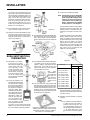
CLEARANCES TO
COMBUSTIBLES
The clearances listed are MINIMUM distances.
Measure the clearance to both the appliance
and the chimney connector. The farthest
distance is correct if the two clearances
do not coincide.
For example, if the appliance is set as indicated
in one of the figures but the connector is too
close, move the stove until the correct clear-
ance to the connector is obtained.
This appliance may be installed only with the
clearances as shown in the situations pic-
tured. Do not combine clearances from
one type of installation with another in
order to achieve closer clearances.
This unit can be installed on a solid combustible
surface like a wood floor. This unit can also be
installed directly on carpeting or vinyl.
Emissions from burning wood or gas could
contain chemicals known to the State of
California to cause cancer, birth defects or
other reproductive harm.

Waterford TARA T25 Direct Vent Freestanding Gas Stove
7
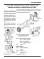
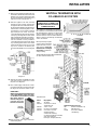
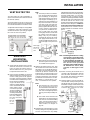
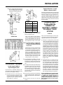
OPTIONAL FAN
INSTALLATION
for units starting with serial #
11106 to 13347 / 217000001 to present.
Fan Kit Contains:
Qty. Description
1 Fan Assembly c/w green wire attached
1 Thermodisc
1 power cord
2 2-1/4" x 20 hex nut
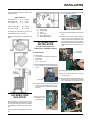
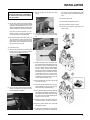
1) Remove the thermodisc from the bracket on
the fan assembly, do not disconnect the
wires.
LOCATING YOUR
GAS STOVE
When selecting a location for your stove,
ensure that the clearances listed above are met
as well as ensuring that there is adequate
accessibility for servicing and proper opera-
tion.
For Vent Termination requirements, see page
10.
A) Cross Corner
B) Room Divider
C) Island
D) Flat on Wall
E) Flat on Wall Corner
F) Flush with Wall/Alcove
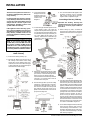
4) Remove the nylon hole plug from the control
panel.
5) Install the fan speed controller onto the
control panel and secure with nut and
washer. Connect the red and black wires
from the wire harness to speed controller.
NOTE: Speed control wires must be in the
down position when control panel is in
place.
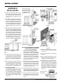
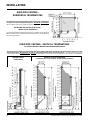
INSTALLATION
Use the minimum clearances shown in the
diagrams below:
TARA Clearances
Side Wall to Unit* A 6" / 150 mm
Back Wall to Unit B 3" / 75 mm
Unit Corner to Wall C 2" / 50 mm
Unit to Alcove Ceiling 13" / 330 mm
Max. Alcove Depth 24" / 610 mm
*If installing the side shelves, which are 6"
wide, additional space is required.
Minimum ceiling height is 47"/1294mm from
floor.
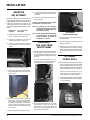
2) Remove the rear access panel on the back
of the stove by removing the 6 screws.
Take care not to cut wires when lowering
the panel.
Thermodisc
Top Control Panel Assembly
Fan Speed
Controller
Rear Access Panel
secured with 6 screws
(3 on each side)
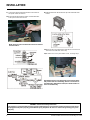
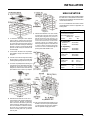
6) Push black knob onto speed control.
7) Re-attach control panel with 3 screws,
reversing step 2.
8) Mount the blower assembly in position un-
der the base of the stove and secure with
the 2 supplied bolts (2-1/4" #20 hex head)
3) Remove the Top Control Panel Assembly by
removing the three screws.

8
Waterford TARA T25 Direct Vent Freestanding Gas Stove
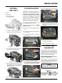
INSTALLATION
9) Connect the red wire from the thermodisc to the red wire of
the speed control wire harness.
10)Connect the live black wire from power cord to the black wire
of the speed control wire harness.
12)Ensure all wires are pulled away from firebox to avoid excessive
heat and secure with stick-on wire clip.
13)Re-attach rear access panel with 6 screws, reversing step 7.
NOTE: Pull excess wire next to fan to avoid excessive heat
from the firebox.
11)Slide the thermodisc into the bracket clip on the underside of the
firebox.
NOTE: When power cord is plugged in, speed control is in the
ON position and stove is burning, allow 10 - 15 minutes for
the thermodisc (temperature switch) to activate and turn on
the Fan automatically.
WARNING: Electrical Grounding Instructions
This appliance is equipped with a three pronged (grounding) plug for your protection against shock hazard and should
be plugged directly into a properly grounded three-prong receptacle. Do not cut or remove the grounding prong from
this plug.

Waterford TARA T25 Direct Vent Freestanding Gas Stove
9
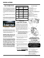
VENTING
INTRODUCTION
The following vent systems in combination with
the Tara Direct Vent Freestanding Gas Stove,
have been tested and listed as direct vent
heater systems by Warnock Hersey:
1) The Minimum Horizontal Termination with
the DV Stove Horizontal Riser Vent Kit
(Part# 640-944)
2) Vertical Termination using Co-Linear Flex
System
3) The DV Stove Horizontal Vent Kit
4) The Simpson Dura-Vent Direct Vent Sys-
tem Model DV-GS venting systems
The Tara uses the "balanced flue" technology
Co-Axial system. The inner liner vents products
of combustion to the outside while the outer
pipe draws outside combustion air into the
combustion chamber thereby eliminating the
need to use heated room air for combustion and
losing warm room air up the chimney.
Note: These flue pipes must not be con-
nected to any other appliance.
The gas appliance and vent system must be
vented directly to the outside of the building, and
never be attached to a chimney serving a
separate solid fuel or gas burning appliance.
Each direct vent gas appliance must use it's
own separate vent system. Common vent sys-
tems are prohibited.
IMPORTANT
Read all instructions carefully before starting
the installation. Failure to follow these instruc-
tions may create a fire or other safety hazard,
and will void the warranty. Be sure to check the
venting and clearance to combustible require-
ments. Consult your local building codes
before beginning installation.
The location of the termination cap must con-
form to the requirements in the Exterior Vent
Terminal Locations diagram on page 10.
INSTALLATION
PRECAUTIONS
These venting systems are engineered prod-
ucts that have been designed and tested for
use with the Tara. The warranty will be voided
and serious fire, health or other safety haz-
ards may result from any of the following
actions:
1) Installation of any damaged Direct Vent
component
2) Unauthorized modification of the Direct
Vent System
3) Installation of any component part not man-
ufactured or approved by Simpson Dura-
Vent or Fireplace Products International
Ltd.
4) Installation other than as instructed by
Simpson Dura-Vent and Fireplace Prod-
ucts International Ltd.
Warning: Always maintain required
clearances (air spaces) to nearby
combustibles to prevent a fire haz-
ard. Do not fill air spaces with insu-
lation.
Be sure to check the vent termination clear-
ance requirements from decks, windows,
soffits, gas regulators, air supply inlets and
public walkways as specified in the Exterior
Vent Terminal Locations on page 9 and in your
local building codes.
The gas appliance and vent system must
be vented directly to the outside of the
building, and never be attached to a chim-
ney serving a separate solid fuel or gas-
burning appliance. Each direct vent gas
appliance must use it's own separate vent
system. Common vent systems are prohibited.
SAFETY
PRECAUTIONS FOR
THE INSTALLER
1) Wear gloves and safety glasses for pro-
tection.
2) Exercise extreme caution when using lad-
ders or on roof tops.
3) Be aware of electrical wiring locations in
walls and ceilings.
COMBUSTION AND
VENTILATION AIR
The combustion air from this appliance is drawn
from outside the building through the outer flue.
Extra provision for combustion air inside
the room is not required.
INSTALLATION

10
Waterford TARA T25 Direct Vent Freestanding Gas Stove
INSTALLATION
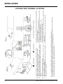
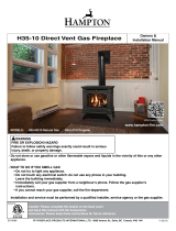
EXTERIOR VENT TERMINAL LOCATIONS
A= Clearance above grade, veranda, porch, deck, or balcony *(min. 12"/30cm)
B= Clearance to window or door that may be opened *(12"/30cm) #(9"/23cm)
C= Clearance to permanently closed window *(min. 12"/30cm)
D= Vertical clearance to ventilated soffit located above the terminal within a horizontal
distance of (24"/60cm) from the centerline of the terminal (min. 18"/46cm) check with
local code.
E= Clearance to unventilated soffit (min. 12"/30cm)
F= Clearance to outside corner: with AstroCap Termination Cap (min. 6"/15cm), with
Dura-Vent Termination Cap (14"/36cm)
G= Clearance to inside corner: with AstroCap Termination Cap (min. 6"/15cm), with Dura-
Vent Termination Cap (12"/30cm)
H= Not to be installed above a meter/regulator assembly within (3'/90cm) horizontally from
the centerline of the regulator.
J= Clearance to service regulator vent outlet *(min. 36"/90cm)
K= Clearance to non-mechanical air supply inlet to building or the combustion air inlet to
any other appliance *(12"/30cm) #(9"/23cm)
L= Clearance to a mechanical air supply inlet *(min. 72"/1.8m)
#3' (91cm) above if within 10' (3m) horizontally.
M= **Clearance above paved sidewalk or a paved driveway located on public property
*(min. 84"/2.1m)
N= Clearance under veranda, porch, deck, or balcony *(min. 12"/30cm)***
Note: * As specified in CGA B149 Installation Code. Note: Local codes or regulations may require different clearances.
**A vent shall not terminate directly above a sidewalk or paved driveway which is located between two single family dwellings and serves both dwellings.
***Only permitted if veranda, porch, deck, or balcony is fully open on a minimum of two sides beneath the floor.
#In accordance with the current ANSI Z223.1 / NFPA 54, National Fuel Gas Code.

Waterford TARA T25 Direct Vent Freestanding Gas Stove
11
INSTALLATION
RESIDENTIAL AND MANUFACTURED HOMES / MOBILE HOMES
MINIUMUM HORIZONTAL TERMINATION INSTALLATIONS
You will require the following components with your new Regency Rear Vent Direct Vent
Freestanding Gas Stove. Please review your product to make sure you have everything you need.
In the event that you are missing any part, contact your dealer.
Decorative brass or chrome trim kits are available from Simpson
Dura-Vent for their wall thimbles, as well as a square
wall thimble cover.
Planning Your venting Installation
See page 9 for Exterior Vent Termination
requirements. The T25 is approved for a
minimum horizontal termination with the Regen-
cy Riser Vent Kit. See the diagram for minimum
and maximum pipe lengths.
When planning your installation, it will be nec-
essary to select the proper length of vent pipe
for your particular requirements. Determine the
minimum clearance to combustibles from the
rear of the unit to the wall. It is also important to
note the wall thickness. Before cutting the vent
hole through the wall ensure that ALL vent and
termination clearances (see page 10) will be
met.
The venting arrangements shown on the dia-
gram, have a minimum of 75% (flue loss)
efficiency with Fan Off, as required for man-
ufactured homes. (Actual efficiency may be as
high as 85%.)
*If this is an outside corner, the minimum dis-
tance between the vent and the outside corner
is 6" (15cm). See "F" on the diagram on page 10.
NOTE: Ensure compliance with the outside vent
terminal location before cutting hole as both
dimensions must be met.
Note: These are the minimum pieces re-
quired. Other parts may be required
for your particular installation.
Minimum components for a Horizontal Installation:
640-944 Horizontal Termination Kit which includes:
1 946-201 6-5/8" Dia. x 18" Black Pipe
1 946-207 4" Dia. x 18" Aluminum Vent
1 946-202 Wall Penetration Heat Shield (Wall Thimble) (2 pcs)
1 640-530 Riser Vent Terminal
1 640-545 Decorative Wall Trim (Black)
1 948-128 Tube Mill-Pac
Screws
945G* 1 45
o
Elbow
946-219 1 Adapter
Optional Components:
946-204 45
o
Elbow - 6-5/8" Black pipe
and 4" Aluminum Vent
946-205 Vinyl Siding Shield for Riser Vent
Terminal
946-208/P Vent Guard
940 Square Wall Thimble Cover*
981 Snorkel Termination (36")*
982 Snorkel Termination (14")*
942 Wall Penetration
Heat Shield*
* Simpson Dura-Vent components

12
Waterford TARA T25 Direct Vent Freestanding Gas Stove
Diagram 4
Diagram 2a
Diagram 3
HORIZONTAL
INSTALLATIONS
1) Set the unit in its desired location. Check to
determine if wall studs are in the way when
the venting system is attached. If this is the
case, you may want to adjust the location
of the unit.
2) Assemble the desired combination of pipe
and elbow to the appliance adapter with
pipe seams oriented down. Offset the pipe
seams as double seams in one place will
cause the outer pipe to take an oval shape.
Kit comes complete with 18" of straight vent
- 6-5/8" dia. black outer pipe and 4" dia. inner
vent.
3) With the pipe attached to the stove, slide the
stove into its correct location, and mark the
wall for a 9-1/2" (inside dimensions) round
hole. The center of the round hole should
line up with the centerline of the horizontal
pipe, as shown in diagram 1. Cut and frame
the 9-1/2 round hole in the exterior wall
where the vent will be terminated. If the wall
being penetrated is constructed of non-
combustible material, i.e. masonry block or
concrete, a 7" diameter hole is acceptable.
Note:
a) The horizontal run of vent should have a 1/
4 inch rise for every 1 foot of run towards
the termination. Never allow the vent to run
downward. This could cause high temper-
atures and may present the possibility of a
fire.
b) The location of the horizontal vent termina-
tion on an exterior wall must meet all local
and national building codes, and must not be
blocked or obstructed. For External Vent
Terminal Locations, see diagram on page 9.
c) Snorkel Terminations:
For installations requiring a vertical rise on
the exterior of the building, 14-inch and 36-
inch tall Snorkel Terminations as shown in
Dia. 2 are available, as well as the standard
Riser Vent. Follow the same installation
procedures as used for standard Horizon-
tal Termination. NEVER install the snorkel
upside down.
Diagram 1
*Dia 2a & 2b: As speci-
fied in CGA B149 Instal-
lation Code. Local codes
or regulations may re-
quire different clearanc-
es.
NOTE: For Snorkel terminations in ABOVE
grade installations, follow national
or local code requirements.
Below Grade Snorkel Installation
If the Snorkel Termination must be installed
below grade, i.e. basement application,
proper drainage must be provided to pre-
vent water from entering the Snorkel Ter-
mination. Refer to Dura-Vent Installation
instructions for details.. Do not attempt to
enclose the Snorkel within the wall, or any
other type of enclosure.
4) Install wall penetration heat shield in the
center of the 9-1/2" round hole and attach
with wood screws. The four wood screws
provided should be replaced with appropri-
ate fasteners for stucco, brick, concrete,
or other types of sidings. Dia. 3.
5) If installing termination on a siding covered
wall, a vinyl siding standoff or furring strips
must be used to ensure that the termination
is not recessed into the siding. Dia. 3.
6) Take the Riser Vent terminal and separate
the Backing Plate from the Riser Vent Front
by removing 8 screws as shown in dia-
gram 4.
INSTALLATION
Diagram 2b
7) Install the Backing Plate into the wall pene-
tration heat shield and attach using 4
screws. Dia. 4.
8) Connect all pipe sections to unit and install
into wall:
a) Measure pipe length required and cut to
length. Hint: use the cut end of the 6-5/8" dia.
outer pipe at the vent terminal end.
b) Push the pipe sections completely together,
the minimum pipe overlap is 1-1/4". Secure
all outer pipe joints by using at least two
screws. Locate the screws at the bottom
of the pipe so that the screw heads are
hidden on the final installation. Apply seal-
ant "Mill-Pac" to inner pipe and high temp
silicone sealant or "Mill-Pac" to outer pipe on
every joint.
Hint: Apply sealant
to female end.

Waterford TARA T25 Direct Vent Freestanding Gas Stove
13
INSTALLATION
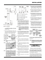
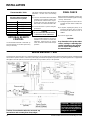
VERTICAL TERMINATION WITH
CO-LINEAR FLEX SYSTEM
This appliance is designed to be attached to
two 3" (76mm) co-linear aluminium flex running
the full length of the chimney. The flue length
must be a minimum length of 8 ' (2.44m) and a
maximum of 35' (10.7m). See chart for minimum
distances from roof. Periodically check that the
vent is unrestricted.
Masonry chimneys may take
various contours which the
flexible liner will accommo-
date. However, keep the
flexible liner as straight
as possible, avoid unnec-
essary bending.
The Air Intake pipe must be attached to the inlet
air collar of the termination cap.
Diagram 5
c) Before connecting the vent pipe to the vent
termination, slide the black decorative wall
thimble cover over the vent pipe, then slide
the Wall Penetration Heat Shield (Part #
946-202) over the vent pipe. Dia. 3.
d) Slide the appliance and vent assembly
towards the wall carefully inserting the
vent pipe into the riser vent terminal assem-
bly. It is important that the vent pipe extends
into the Riser Vent Backing Plate a suffi-
cient distance so as to result in a minimum
pipe overlap of 1-1/4 inches. Secure the
connection between the vent pipe and the
vent cap by attaching the two sheet metal
strips extending from the Riser Vent Back-
ing Plate into the outer wall of the vent pipe.
Use two aluminum screws provided to
connect the strips to the pipe section. Bend
any remaining portion of the sheet metal
strip back towards the vent cap and cut off
any excess, it will be concealed by the
decorative wall thimble cover. See diagram
5.
8) Slide the decorative wall thimble up to the
wall surface being careful not to scratch
the paint. See diagram 5.
9) Back outside: Apply sealant to the 4" inner
flue and slide the Riser Vent Front into the
Backing Plate and fasten with 8 screws.
IMPORTANT:
When connecting the pipe to the Riser
Vent, apply Mill-Pac to the inner pipe
on the Riser Vent Terminal, around
the bead. Ensure
that the vent pipe is
pushed past the
bead for a secure fit.
10)Seal around the outer edge of the Riser
Vent Backing Plate.
Required Parts:
Part # Description
945G 45
o
Elbow
946-529 Co-linear DV Vertical
Termination Cap
948-305 3" Flex - 35 ft.
270-944 U27 Dura-Vent Adapter
946-563 Co-Axial to Co-Linear
Adapter Kit which
contains the following:
Co-linear Flex Adapter (270-585)
Outer Pipe (946-257)
Inner Pipe Adapter (946-219)
Alternate Approved Caps
980 Vertical Termination Cap
991 High Wind Cap
923GK 3" Co-linear Adapter
with flashing
THE APPLIANCE MUST NOT BE
CONNECTED TO A CHIMNEY FLUE
SERVING A SEPARATE SOLID FUEL
BURNING APPLIANCE.

14
Waterford TARA T25 Direct Vent Freestanding Gas Stove
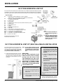
DV STOVE HORIZONTAL VENT KIT (#946-116 & #946-216) INSTALLATION
Review the following sequence of instructions
which are typical of most installations. The
sequence may vary depending on wall thick-
ness. Refer to pages 11 to 18 for vent
location and clearance dimensions.
1) Set the unit in its desired location. Check to
determine if wall studs will be in the way of
the venting system, adjust location until all
clearances are met and there are no ob-
structions.
c) Attach the 2 piece adjustable pipe
section to the vent terminal and slide
into position from the exterior. The
larger diameter end of the ad-
justable pipe goes to the vent
terminal.
d) Install the 90
o
elbow onto the adjusta-
ble pipe to determine the vertical
centerline.
Note: if the centerline cannot be
met, the adjustable sections will
have to be cut.
e) Cut the 2 ft. or 4 ft. section of rigid pipe
to length. Attach the 45
o
elbow to the
rigid pipe, and ensure that the pipe
length when cut (with the 45
o
elbow)
will seat onto both the starter collar
and the 90
o
elbow. Crimped sec-
tion of rigid pipe seats into the 90
o
elbow. Only cut the uncrimped
side of pipe.
Dismantle all pipe sections including vent
terminal.
3) Attach the 4" dia. flex liner to the vent
terminal ensuring that the flex overlaps
the collar of the vent terminal by a minimum
Note: A 1-1/2"(38mm) clearance around
the outer pipe must be maintained
except that only a 1" (25mm) clear-
ance is needed at the termination
end.
IMPORTANT:
Do not locate termination hood
where excessive snow or ice build-
up may occur. Be sure to check
vent termination area after snow
falls, and clear to prevent acciden-
tal blockage of venting system.
When using snow blowers, make
sure snow is not directed towards
vent termination area.
2) Assemble a trial fit to determine the ver-
tical center-line for the vent termination.
a) Cut a 9-1/2" x 9-1/2" (241mm x 241 mm)
square hole on both the interior and
exterior wall.
b) Install wall thimbles on both interior and
exterior wall with 4 wood screws (#8
x 1") per thimble.
DV STOVE HORIZONTAL VENT KIT
DV Stove Horizontal Vent Kit (2 ft. Part # 946-116 or 4 ft. Part # 946-216) includes all the parts needed
to install the U29-2 or U45-3 with minimum horizontal and vertical vent dimensions. For installations
that require longer vertical and/or horizontal vents use the Dura-Vent system as shown on page 18.
Qty. Description
1) 1 Rigid Pipe Section (Kit # 946-116: 2 ft. (1.2m) length,
Kit # 946-216: 4 ft. (1.2m) length), 6-1/2" (165mm) inside diameter
2) 1 Flex Liner, compressed aluminium 2 ply liner,
4" (102mm) inside diameter
3) 4 spring spacers
4) 1 90 deg. Elbow
5) 1 Adjustable pipe section 13-1/2" to 24" (343mm x 610mm), 2 pieces
6) 1 Thimble Cover
7) 1 Wall Thimble (2 pcs.)
8) 1 Adapter
9) 1 AstroCap Termination Cap
10) 2 Trim Collar
11) 1 tube of Mill-Pac, high temperature sealant
12) 12 Screws, #8 x 1/2" Self tapping, Stainless Steel
13) 14 Screws, #8 x 1/2" Self tapping, Black
14) 4 Screws #8 x 1-1/2" Drill Point, Black
15) 4 Screws #8 x 1-1/2" Drill Point, Stainless Steel
16) 8 Wood screws #8 x 1"
Required but not included in above Kit:
45
o
Elbow (Part #: 946-214)
Note:
a) Liner sections should be con-
tinuous without any joints or
seams.
b) This is an approved system,
therefore components in this
system must not be substi-
tuted for any other manufac-
turer's products.
INSTALLATION

Waterford TARA T25 Direct Vent Freestanding Gas Stove
15
DURA-VENT
TERMINATION KIT
Planning Your Dura-Vent Installation
There are two basic types of Dura-Vent Direct
Vent System installations: horizontal termina-
tion and vertical termination. Confirm the max-
imum horizontal run and maximum vertical rise
from the diagram on page 18.
When planning your installation, it will be nec-
essary to select the proper length of vent pipe
for your particular requirements. For horizontal
installations, determine the minimum clearance
INSTALLATION
of 1-3/8"(35mm). Use Mill-Pac to seal and
secure with 3 of the #8 x 1/2" screws
(stainless steel).
4) Attach the adjustable pipe section to the
vent terminal using Mill-Pac and/or high
temperature silicone and attach with 3 of
the #8 x 1/2" screws (stainless steel).
Note: The pipe seam should be facing
down.
Note: To make the
installation
more aesthet-
ically pleasing,
we recom-
mend framing
out a square
that the cap can
be mounted
on.
Note: If installing termination on a siding
covered wall, a vinyl siding stand-
off or furring strips must be used
to ensure that the termination is
not recessed into the siding. For
vinyl siding standoff installation
refer to the Dura-Vent Termina-
tion instructions.
5) Slide the partially connected pipe and vent
terminal assembly through the wall thimbles
(from the exterior into the interior) and
secure the cap to the exterior wall with 4 of
the supplied screws (#8 x 1-1/2" drill point,
stainless steel). Note: pilot holes will need
to be drilled through the wall thimble on all
4 corners.
Note: The four screws provided for the
vent cap should be replaced with
appropriate fasteners for stucco,
brick, concrete, or other types of
sidings.
6) A bead of non-hardening mastic should be
run around both the termination and vinyl
siding standoff to prevent water from en-
tering and to make a tight seal between the
cap and the standoff.
7) Stretch the 4" dia. flex liner out fully and get
a trial fit of the liner onto the 4" dia. starter
collar.
8) Cut the 4" dia. flex liner to the desired size.
Hint: leave an extra 12" to 16" of length, this
will make the final assembly easier to work
with.
9) Secure the 4" dia. flex liner to the 4" adapter
with Mill-Pac and 3 of the #8 x 1/2" screws
(stainless steel).
10)Slide the decorative Thimble Cover over the
pipe sections and secure with 4 screws
(#8 x 1-1/2" drill point, black) to the wall.
11)Slide the 90
o
elbow (crimp end up), the 45
o
elbow and the 2 ft. or 4 ft. pipe section
(crimp end up) over the 4" dia. flex liner.
12)Slide the trim collar over the adjustable pipe
sections to cover the joint of the telescopic
section.
13)Install the spring spacers onto the pipe
sections.
14)Secure the 4" dia. flex liner with adapter
onto the stove collar. Put a bead of Mill-Pac
around the appliance adapter and secure
with 3 screws (#8 x 1/2, stainless steel).
15)Attach the 45
o
elbow onto the starter collar
by sealing with Mill-Pac and/or high tem-
perature silicone and securing with 3 of
the #8 x 1/2" (black) screws.
16)Attach the pipe section to the 45
o
elbow by
sealing with Mill-Pac and/or high tempera-
ture silicone and securing with 3 of the #8
x 1/2" screws (black). Pipe seams should
be facing the wall.
17)Attach the 90
o
elbow onto the pipe section
by sealing with Mill-Pac and/or high tem-
perature silicone and securing with 3 of
the #8 x 1/2" screws (black).
18)Slide the adjustable pipe section onto the
90
o
elbow. The flex may have to be com-
pressed back in order for the adjustable
pipe to properly mate to the elbow. Seal
with Mill-Pac and/or high temperature sil-
icone and secure with 3 of the #8 x 1/2"
screws (black). Pipe seams facing down.
18)Install the trim collar over the starter collar
and secure with a #8 x 1/2" screw (black).
If the pipe needs to be touched up, use only
Stove Brite High Temperature Metallic Black
Stove Paint.
NOTE: All inner joints must be sealed
with Mill-Pac. All outer joints may
be sealed with high temperature
silicone.
Hint: Apply the
sealant (Mill-
Pac and/or high
temperature sil-
icone) to the out-
er pipe before
connecting the
inner pipe.

16
Waterford TARA T25 Direct Vent Freestanding Gas Stove
INSTALLATION
from the rear of the unit to the wall. It is also
important to note the wall thickness. (The wall
thimble is suitable for 2 x 4 or 2 x 6 wall
construction.) Select the amount of vertical rise
desired for "vertical-to-horizontal" type instal-
lations.
The minimum clearance of 1-1/4" (32mm) is
required between the outer wall of the vent pipe
and nearby combustible surfaces. Be sure to
check the vent termination clearance require-
ments from decks, windows, soffits, gas reg-
ulators, air supply inlets and public walkways
as specified in the Exterior Vent Terminal
Locations on page 9 and in your local building
codes.
To determine the length of vent pipe required
for vertical installations, measure the distance
from the unit flue outlet to the ceiling, the ceiling
thickness, the vertical rise in an attic or second
storey, and allow for sufficient vertical height
Parts not supplied by Dura-Vent
946-506/P Vent Guard (Optional)
640-530 Riser Vent Terminal (Optional)
948-128 Vinyl Siding Shield for Riser Vent
Terminal
946-228 Horizontal Square Termination
Cap
You will require the following components
with your new Waterford Direct Vent Free-
standing Gas Stove. Please review your prod-
uct to make sure you have everything you
need. In the event that you are missing any
part, contact your dealer.
above the roof line.
For multi-storey applications, fire stops are
required at each floor level. If an offset is
needed, additional pipe, elbows and supports
will be required.
Do not exceed the maximum number of elbows.
One 90
o
for horizontal terminations and two 45
o
for vertical termination.
Note: These are the minimum pieces
required. Other parts may be re-
quired for your particular installa-
tion. See page 15 for a list of vent
parts.
If installing termination on a siding covered
wall, a vinyl siding standoff or furring strips
can be used in order to ensure that the termi-
nation is not recessed into siding.
The vinyl siding standoff is required for walls
with vinyl siding.
Minimum components for a Dura-Vent
Horizontal Installation:
A) Dura-Vent Horizontal
Termination Cap
B) Round Support Box/Wall Thimble
C) Pipe Length (length varies)
D) 90
o
Elbow
E) Pipe Length (Min. 24")
F) Adapter (Part # 946-219)
G) 45
o
Elbow (Part # 945B)
Minimum components for a Dura-Vent
Vertical Termination:
H) Dura-Vent Vertical Termination Kit
See page 16 for pipe lengths.
RIGID PIPE VENTING COMPONENTS
Dura-Vent Basic
Horizontal Kit # 970
1 90
o
Elbow
1 Wall Thimble Cover
1 Horiz. Sq. Term. Cap
AstroCap
Part# 946-523/P
Alternate Horizontal
Termination Caps
Alternate
Horizontal
Riser Vent
Terminal
Part# 640-530/P
This product has been evaluated by Intertek for
using a Dura-Vent Flue Adaptor in conjunction
with Selkirk Direct-Temp and Ameri Vent Direct
venting systems. Use of these systems with
the Direct Vent GS starting collar is deemed
acceptable and does not affect the Intertek WHI
listing of components.
WARNING:
Do not combine venting components from
different venting systems.
However use of the the AstroCap
TM
and FPI
Riser is acceptable with all systems.
When using piping other than Simpson
Dura-Vent, 3 screws must be used to
secure rigid pipe to adaptor.
The FPI AstroCap
TM
and FPI Riser Vent terminal is certified for installations using FPI venting
systems as well as Simpson Dura-Vent®, Direct Vent GS, American Metal Products, Ameri
Vent Direct vent and Selkirk Direct-Temp. FPI
TM
, and FPI AstroCap
TM
are the proprietary
trademarks of FPI Fireplace Products International Ltd. Dura-Vent® and Direct Vent GS are
registered and/or proprietary trademarks of Simpson Dura-Vent Co. Inc.

Waterford TARA T25 Direct Vent Freestanding Gas Stove
17
INSTALLATION
RIGID PIPE VENTING COMPONENTS LIST
All Simpson Dura-Vent components are available directly from FPI.
Description Simpson Dura-Vent Selkirk Amerivent
R
Direct VentGS
R
Direct-Temp
TM
Direct Vent
6" Pipe Length, Galvanized 908 4DT-6 N/A
6" Pipe Length, Black 908B 4DT-6B N/A
7" Pipe Length, Galvanized N/A N/A 4D7
7" Pipe Length, Black N/A N/A 4D7B
9" Pipe Length, Galvanized 907 4DT-9 N/A
9" Pipe Length, Black 907B 4DT-9B N/A
12" Pipe Length, Galvanized 906 4DT-12 4D12
12" Pipe Length, Black 906B 4DT-12B 4D12B
18" Pipe Length, Galvanized N/A 4DT-18 N/A
18" Pipe Length, Black N/A 4DT-18B N/A
24" Pipe Length, Galvanized 904 4DT-24 4D2
24" Pipe Length, Black 904B 4DT-24B 4D2B
36" Pipe Length, Galvanized 903 4DT-36 4D3
36" Pipe Length, Black 903B 4DT-36B 4D3B
48" Pipe Length, Galvanized 902 4DT-48 4D4
48" Pipe Length, Black 902B 4DT-48B 4D4B
Adjustable Length, 11"-14", Galv. 911 4DT-AJ N/A
Adjustable Length, 11"-14", Black 911B 4DT-AJB N/A
Adjustable Length, 17"-24", Black 917B N/A N/A
Adjustable Length, 7" Galvinized N/A N/A 4D7A
Adjustable Length, 7" Black N/A N/A 4D7AB
Adjustable Length, 12" Galvinized N/A N/A 4D12A
Adjustable Length, 12" Black N/A N/A 4D12AB
45
O
Elbow, Galvinized 945 4DT-EL45 4D45L
45
O
Elbow, Black 945B 4DT-EL45B 4D45LB
45
O
Elbow, Swivel, Galvinized 945G N/A N/A
45
O
Elbow, Swivel, Black 945BG N/A N/A
90
O
Elbow, Galvinized 990 4DT-EL90S 4D90LS
90
O
Elbow, Black 990B 4DT-EL90SB 4D90LBS
90
O
Elbow, Swivel, Galvinized 990G N/A N/A
90
O
Elbow, Swivel, Black 990BG N/A N/A
Ceiling Support 949 - n/a from FPI 4DT-CS 4DFSP
Cathedral Support Box 941 4DT-CSS 4DRSB
Wall Support/Band 988 4DT-WS/B 4DWS
Offset Support 989 - n/a from FPI 4DT-OS N/A
Wall Thimble, Black 942 4DT-WT 4DWT
Wall Thimble Support Box/Ceiling Support 940 N/A N/A
Firestop Spacer 963 4DT-FS 4DFSP
Trim Plate, Black N/A 4DT-TP 4DFPB
Brass Trim for Wall Thimble/Ceiling Support 3951 N/A N/A
Attic Insulation Shield 12" N/A N/A 4DAIS12
Attic Insulation Shield - Cold Climates 36" N/A N/A 4DAIS36
Basic Horizontal Termination Kit (A) 970 4DT-HKA 4DHTK2
Horizontal Termination Kit (B) 971 4DT-HKB 4DHTK1
Vertical Termination Kit 978 4DT-VKC 4DVTK
High Wind Vertical Cap 991 N/A N/A
High Wind Horizontal Cap 985 N/A N/A
Horizontal Square Termination Cap 984 4DT-HHC 4DHC
Verical Termination Cap 980 4DT-HVC 4DVC
Storm Collar 953 4DT-SC 4DSC
Adjustable Flashing, 0/12-6/12 943 4DT-AF6 4DF
Adjustable Flashing, 6/12-12/12 943S 4DT-AF12 4DF12
Vinyl Siding Standoff 950 4DT-VS N/A
Vinyl Siding Shield Plate N/A 4DT-VSP N/A
Snorkel Termination 14" 982 4DT-ST14 4D12S
Snorkel Termination 36" 981 4DT-ST36 4D36S
946-506/P Vent Guard (Optional)
946-205 Vinyl Siding Shield for Riser Vent Terminal
946-208/P Vent Guard (Optional) - Riser Vent Terminal
946-523/P AstroCap Horizontal Cap
946-206 Vinyl Siding Standoff - AstroCap
640-530/P Riser Vent Terminal

18
Waterford TARA T25 Direct Vent Freestanding Gas Stove
INSTALLATION
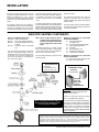
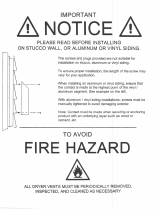
RIGID PIPE VENTING - VERTICAL TERMINATIONS
for both Residential & Manufactured Homes/Mobile Homes
The shaded areas in the two diagrams below show all allowable combinations of straight vertical and offset to vertical runs with
vertical terminations. Maximum two 45
o
elbows (not including the 45
o
elbow attached to the unit.). All vertical and offset to vertical
vent installations require Vent Restrictor #1. If the vent is ENCLOSED in a chase (min. size 9" x 9") maintain a 1-1/4" clearance to combustibles.
Offset to Vertical Terminations
Vent Restrictor must be set at 5/8" for this venting installation.
Straight Vertical
Terminations
RIGID PIPE VENTING -
HORIZONTAL TERMINATIONS
The shaded area in the diagram below shows all allowable combinations
of vertical runs with horizontal terminations. Maximum one 90
O
elbow
(two 45
o
elbows equal one 90
o
elbow) using Dura-Vent Venting Systems
Residential and Manufactured Homes /
Mobile Homes Installations
The venting arrangements diagrammed below, have a minimum of 75% (flue loss)
efficiency with Fan Off, as required for manufactured homes. (Actual efficiency
may be as high as 85%.)

Waterford TARA T25 Direct Vent Freestanding Gas Stove
19
b) Horizontal runs of vent must be sup-
ported every three feet. Wall straps
are available for this purpose.
3) With the pipe attached to the stove, slide
the stove into its correct location, and mark
the wall for a 10" x 10" (inside dimensions)
square hole. The center of the square hole
should line up with the centerline of the
horizontal pipe. Cut and frame the 10 inch
square hole in the exterior wall where the
vent will be terminated. If the wall being
penetrated is constructed of non-combus-
tible material, i.e. masonry block or con-
crete, a 7" diameter hole is acceptable.
Note:
a) The horizontal run of vent should
have a 1/4 inch rise for every 1 foot
of run towards the termination. Nev-
er allow the vent to run downward.
This could cause high temperatures
and may present the possibility of a
fire.
b) The location of the horizontal vent
termination on an exterior wall must
meet all local and national building
codes, and must not be blocked or
obstructed. For External Vent Ter-
minal Locations, see diagram on
page 10.
4) If installing the vent termination to a wall
with vinyl siding, the Vinyl Siding Standoff
must be used. Attach the Vinyl Siding
DURA-VENT
HORIZONTAL
INSTALLATIONS
1) Set the unit in its desired location. Check to
determine if wall studs or roof rafters are
in the way when the venting system is
attached. If this is the case, you may want
to adjust the location of the unit.
2) Direct Vent pipe and fittings are designed
with special twist-lock connections to con-
nect the venting system to the appliance
flue outlet. A twist-lock appliance adapter
is installed on the unit at the factory. Assem-
ble the desired combination
of pipe and elbows to the
appliance adapter with pipe
seams oriented towards the
wall or ceiling, as much
out of view as possible.
The final positioning of
the pipe and 90
o
elbow
assembly is determined
by the mounting orienta-
tion of the adapter on
the stove and twist-
locked
for a sol-
id con-
nection.
Diagram 1
Note:
a) Twist-lock procedure: Four indenta-
tions, located on the female ends of
pipes and fittings, are designed to
slide straight onto the male ends of
adjacent pipes and fittings, by ori-
enting the four pipe indentations so
they match and slide in to the four
entry slots on the male ends (dia-
gram 1). Push the pipe sections com-
pletely together, then twist-lock one
section clockwise approximately
one-quarter turn, until the two sec-
tions are fully locked. The female
locking lugs will not be visible from
the outside on the Black Pipe or
fittings. They may be located by
examining the inside of the female
ends. Apply sealant "Mill-Pac" to in-
ner pipe and high temp silicone seal-
ant to outer pipe on every twist-lock
joint.
Hint: Apply
silicone to
female
end.
Diagram 2
Standoff to the Horizontal Vent Termination,
but first run a bead of non-hardening mastic
around its outside edges, so as to make a
seal between vent cap and the standoff.
Install the Vinyl Siding Standoff (Part # 950)
between the vent cap and the exterior wall
and attach with the four wood screws
provided. Seal around the Vinyl Siding Stand-
off on all four sides. Diagram 2. The arrow
on the vent cap should be pointing up.
Insure that the 1-1/4" clearances to com-
bustible materials are maintained. See dia-
gram 2.
VENT RESTRICTOR
The above Offset to Vertical Installation re-
quires more restriction, the Vent Restrictor must
be set to 5/8" (16mm).
The Vent Restrictor on the stove comes preset
with a 7/8" (22mm) opening. The Vent Restrictor
is located inside the firebox over the flue outlet.
To adjust the restrictor simply use a large phillips
screwdriver to loosen the 2 retaining screws
and slide the restrictor up to a 5/8" gap. Tighten
the screws to secure it in position.
INSTALLATION
Note: If installing termination on a siding
covered wall, a vinyl siding stand-
off or furring strips must be used
to ensure that the termination is
not recessed into the siding. The
four wood screws provided
should be replaced with appropri-
ate fasteners for stucco, brick,
concrete, or other types of sid-
ings.
5) Before connecting the horizontal run of
vent pipe to the vent termination, slide the
black decorative wall thimble cover over
the vent pipe, then slide the Wall Thimble
(Part # 942) over the vent pipe.
6) Slide the appliance and vent assembly to-
wards the wall carefully inserting the vent
pipe into the vent cap assembly. It is impor-
tant that the vent pipe extends into the vent
cap a sufficient distance so as to result in
a minimum pipe overlap of 1-1/4 inches.
Diagram 3

20
Waterford TARA T25 Direct Vent Freestanding Gas Stove
Diagram 9
Diagram 8: The upper half of the flashing is
installed under the roofing material and not
nailed down until the chimney is installed.
This allows for small adjustments.
INSTALLATION
Diagram 7
Diagram 5
Diagram 6
5) Cut a hole in the roof centred on the small
drilled hole placed in the roof in Step 2. The
hole should be of sufficient size to meet the
minimum requirements for clearance to com-
bustibles of 1-1/4". Slip the flashing under
the shingles (shingles should overlap half
the flashing) as per diagram 8.
DURA-VENT VERTICAL
TERMINATION
Secure the connection between the vent
pipe and the vent cap by attaching the two
sheet metal strips extending from the vent
cap assembly into the outer wall of the vent
pipe. Use the two sheet metal screws
provided to connect the strips to the pipe.
Bend any remaining portion of the sheet
metal strip back towards the vent cap, so
it will be concealed by the decorative wall
thimble cover. See diagram 3.
7) Install wall thimble in the center of the 10"
square and attach with wood screws.
8) Slide the decorative wall thimble up to the
wall surface being careful not to scratch
the paint and attach with screws provided.
Apply decorative brass or chrome trim if
desired. See diagram 4.
Note: Apply
sealant "Mill-Pac"
to inner pipe and
high temp sili-
cone sealant or
"Mill-Pac" to out-
er pipe on every
joint.
Diagram 4
1) Maintain the 1-1/4" clearanc-
es (air spaces) to combus-
tibles when passing through
ceilings, walls, roofs, enclo-
sures, attic rafter, or other
nearby combustible surfac-
es. Do not pack air spaces
with insulation. Check page
16 for the maximum vertical
rise of the venting system
and the maximum horizontal
offset limitations.
2) Set the gas appliance in its
desired location. Drop a plumb
bob down from the ceiling to
the position of the appliance
flue exit, and mark the loca-
tion where the vent will pen-
etrate the ceiling. Drill a
small hole at his point. Next,
drop a plumb bob from the
roof to the hole previously
drilled in the ceiling, and
mark the spot where the
vent will penetrate the
roof. Determine if ceiling
joists, roof rafters or other
framing will obstruct the vent-
ing system. You may wish to relocate the
appliance or to offset, as shown in diagram
6 to avoid cutting load bearing members.
4) Assemble the desired lengths of black pipe
and elbows necessary to reach from the
appliance adapter up though the Round
Support Box. Insure that all pipes and
elbow connections are in the fully twist-
locked position and sealed.
3) To install the Round Support Box/Wall Thim-
ble in a flat ceiling, cut a 10 inch square hole
in the ceiling centred on the hole drilled in
Step 2. Frame the hole as shown in diagram
7.
6) Continue to assemble pipe lengths.
Note: If an offset is necessary in the attic
to avoid obstructions, it is impor-
tant to support the vent pipe every
3 feet, to avoid excessive stress
on the elbows, and possible sep-
aration. Wall straps are available
for this purpose. See diagram 4.
Galvanized pipe and elbows may be utilized
in the attic as well as above the roofline. The
galvanized finish is desirable above the
roofline due to its higher corrosion resist-
ance.
Continue to add pipe sections through the
flashing until the height of the vent cap
meets the minimum height requirements
specified in diagram 9 or local codes. Note
that for steep roof pitches, the vertical
height must be increased. A poor draft, or
down drafting can result from high wind
conditions near big trees or adjoining roof
lines, in these cases, increasing the vent
height may solve the problem.
7) Ensure vent is vertical and secure the base
of the flashing to the roof with roofing rails,
slide storm collar over the pipe section and
seal with a mastic.
8) Install the vertical termination cap by twist
locking it.
Notes:
a) For multistorey vertical installations,
a Ceiling Fire stop (Part # 963) is
required at the second floor, and
any subsequent floor. Diagram 10.
The opening should be framed to 10
" x 10" inside dimensions, in the
same manner as shown in diagram
7.
Roof Pitch Minimum Vent Height
Feet Meters
flat to 7/12 2 0.61
over 7/12 to 8/12 2 0.61
over 8/12 to 9/12 2 0.61
over 9/12 to 10/12 2.5 0.76
over 10/12 to 11/12 3.25 0.99
over 11/12 to 12/12 4 1.22
over 12/12 to 14/12 5 1.52
over 14/12 to 16/12 6 1.83
over 16/12 to 18/12 7 2.13
over 18/12 to 20/12 7.5 2.29
over 20/12 to 21/12 8 2.44
Page is loading ...
Page is loading ...
Page is loading ...
Page is loading ...
Page is loading ...
Page is loading ...
Page is loading ...
Page is loading ...
Page is loading ...
Page is loading ...
Page is loading ...
Page is loading ...
Page is loading ...
Page is loading ...
Page is loading ...
Page is loading ...
-
 1
1
-
 2
2
-
 3
3
-
 4
4
-
 5
5
-
 6
6
-
 7
7
-
 8
8
-
 9
9
-
 10
10
-
 11
11
-
 12
12
-
 13
13
-
 14
14
-
 15
15
-
 16
16
-
 17
17
-
 18
18
-
 19
19
-
 20
20
-
 21
21
-
 22
22
-
 23
23
-
 24
24
-
 25
25
-
 26
26
-
 27
27
-
 28
28
-
 29
29
-
 30
30
-
 31
31
-
 32
32
-
 33
33
-
 34
34
-
 35
35
-
 36
36


Ask a question and I''ll find the answer in the document
Finding information in a document is now easier with AI
Related papers
-
 Regency Fireplace Products U37-LP PROPANE User manual
-
 Regency Fireplace Products Classic C34 User manual
-
 Regency Fireplace Products U37-LP PROPANE User manual
-
 Regency Fireplace Products U39-LP User manual
-
Regency U37-NG User manual
-
-
-
 Regency Fireplace Products U39 Owner's manual
-
 Regency Fireplace Products H27 Owner's manual
-
 Regency Fireplace Products H35 Owner's manual


Other documents
-
KitchenAid KPEC992MSS1 User manual
-
Del Hutson Designs DHD2002wln Operating instructions
-
TRIANGLE TUBE Horizontal Vent Termination Kit Operating instructions
-
 Wallecover 1-627843367703 Operating instructions
-
 George Kovacs GKST1004-084 User manual
-
George Kovacs GKST1006-084 User manual
-
-
 The Forever Cap FDVC4 Installation guide
-
Simpson Dura-Vent 5"x 8" Direct Vent System Installation Instructions Manual
-
 Command 03BFR Installation guide


