AMERITRON AL-1200 User manual

Category
Audio amplifiers
Type
User manual

This manual is also suitable for

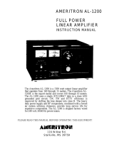
AMERITRON AL-1200 is a high-power linear amplifier designed for amateur radio enthusiasts. It delivers an impressive 1200 watts PEP output power, making it suitable for long-distance communication and contesting. The AL-1200 boasts a rugged construction with forced-air cooling to ensure reliable operation even under demanding conditions. It features a built-in SWR/power meter for monitoring your signal and antenna performance. With its intuitive controls and comprehensive protection circuitry, the AMERITRON AL-1200 offers a user-friendly experience and peace of mind during operation.

AMERITRON AL-1200 is a high-power linear amplifier designed for amateur radio enthusiasts. It delivers an impressive 1200 watts PEP output power, making it suitable for long-distance communication and contesting. The AL-1200 boasts a rugged construction with forced-air cooling to ensure reliable operation even under demanding conditions. It features a built-in SWR/power meter for monitoring your signal and antenna performance. With its intuitive controls and comprehensive protection circuitry, the AMERITRON AL-1200 offers a user-friendly experience and peace of mind during operation.

AMERITRON QSK-5PC Instruction
Manual
AMERITRON QSK-5PC
T/R SWITCH PC BOARD
INTRODUCTION
The Ameritron QSK-5PC is a PIN diode QSK circuit board designed
for use in Ameritron's AL-80A, AL-80B, AL-82, AL-1500 and AL-
1200 amplifiers. Ameritron can not assist customers with the
installation of the QSK-5PC in any amplifier other than these
five units. The QSK-5PC is rated to carry the full power of
these amplifiers except on SSTV, RTTY and PACKET. On these high
duty cycle modes the QSK-5PC will handle a maximum of 1000 watts
with a 5 minute on and two minute off duty cycle.
Ameritron also offers a "stand-alone" PIN diode QSK adapter
called the QSK-5. The QSK-5 is an entirely self-supporting unit
with an internal power supply. The QSK-5 is the best choice for
applications where maximum convenience and flexibility is de-
sired. The QSK-5 connects to the station equipment with standard
connectors to facilitate installation and removal.
QSK BOARD OPERATION
Keying Circuit Timing:
The timing of the transceiver keying circuit is critical with
any QSK switch. The transceiver MUST
have the proper sequencing
of RF and QSK output lines. The transceiver QSK line must pull
low BEFORE RF appears on the output connector and release AFTER
the RF envelope reaches zero to operate with any QSK switch. A
few transceivers do not meet this requirement even though they
are advertised as QSK transceivers. There is no way to
completely correct this problem without modifying the
transceiver.
One indication of improper timing is the flashing or failure of
fuse lamps LP1 and LP2. These lamps protect the transceiver
from failure of the receive diodes. Any component failure that
causes the receive diodes to conduct during the time interval
the transmit diodes are conducting will connect the amplifier's
output directly to the input. This may result in an oscillation
AMERITRON QSK-5PC Instruction
Manual
that can cause damage to the transceiver. NEVER REMOVE OR
DEFEAT THESE LAMPS. They will only fail if there is a timing
or component problem. If you remove the fuse lamps, the
transceiver may be damaged. If the lamps flash or fail, a simple
test can be made by sending a string of very slow dashes with a
keyer. Slowly raise the power on the transceiver until the
lamps begin to flash. If the lamps flash at the beginning or end
of each dash, the timing of the QSK line from the radio is at
fault. If the lamps light throughout the entire length of the
dash the QSK line should be unplugged and the RLY jack of the
amplifier should be grounded. If the lamps still light, then
the QSK switch has a circuit problem. If the lamps do not
light, the problem is in the radio or the connection to the
radio. Another indication of improper timing is the generation
of clicks or leading or trailing edge "chopping" of the signal.
This indicates hot switching is occurring. This is strictly a
timing problem.
Timing can be measured with a dual trace scope. The triggered
trace should be connected to the QSK output line of the trans-
ceiver(open collector lines will need a pull-up resistor con-
nected to 12 volts) and the RF output monitored with the other
trace. RF must not appear until one millisecond after the QSK
line is low. The QSK output line of the transceiver must not
go high before the RF envelope drops to zero.
RECEIVE:
In RECEIVE the QSK board functions as follows: When terminal
D is high, R10 and R16 bias Q5 into conduction. This holds the
collector of Q5 below three volts. IC1A and B are biased at 50%
of the supply voltage with the inputs arranged so that IC1B is
on in this mode. IC1B turns Q4 on and this pulls the base of Q3
low removing the high voltage from the receive diodes(D2, 3, 4
and 11) and grounding the junction at L6. This allows 12 volts
to flow through the diode string from L5 and L7 to the common
cathode point at L6. This turns the receive diodes on. R17 and
C19 control the time delay of the receive diode turn on to
insure the transmit diodes have time to turn off before the
receive diodes are turned on.
IC1A will be off when terminal D is high and Q2 will not
conduct. This allows Q1 to be forward biased by R5 and pull L2
up to 400 volts. This voltage cuts off D1 first and then D10, 9,
8 and 7. This disconnects the input of the amplifier before
disconnecting the output.
AMERITRON QSK-5PC Instruction
Manual
TRANSMIT:
In TRANSMIT the circuit functions as follows: Point D is held
below 2 volts. This removes the forward bias on Q5 and allows
the collector to go high. IC1A turns on after a slight delay
caused by the charge time of R18 and C20. Q2 turns on and
discharges the transmit diode string through D5. Q1 is forced
off by the removal of base bias by Q2. The 12 volt supply then
flows from R27 through the diode string to Q2. This places the
transmit diodes in conduction by biasing them with
approximately 600 mA of forward current.
The receive diodes are disabled when Q5's collector voltage
charges C19 quickly through D13. This turns IC1B off which turns
Q4 off. This allows R6 to pull the base of Q3 high and the
voltage at the emitter of Q3 rapidly turns the center junction
of the receive diodes off by applying 380 volts of positive bias
to L6.
Voltage divider R8 and R12 allows IC1C to compare the status of
the receive diode bias to the voltage obtained through R11
from the transmit diode string. If the transmit diode string
is off and the receive diode string is on, the output of IC1C
will be low and Q6 and Q7 will be off. When the transmit diode
string is on and the receive diode string is off Q6 and Q7 are
biased into conduction.
Q7 can be used to switch the bias in an amplifier. The source
(terminal J) must be within 3 volts of ground and the drain
(terminal I) must be below 25 volts positive. The FET will
safely carry two amperes of current.
Q6 can be used to pull up to 100 mA of current to ground
(terminal K). The open circuit voltage must be below 25 volts
and positive polarity.
AMPLIFIER CONNECTIONS
The QSK-5PC installation requires modifications of the wiring to
the phono jacks on the amplifiers. The following is a list of
the new functions of the amplifier rear panel jacks:
12 V:
This jack is used to supply 12 volts for external accessories.
This jack can also be used for a "hand-shake" that confirms the
diodes have changed states. Optional instructions will connect
this jack to the open collector output of Q6 for the "hand-
AMERITRON QSK-5PC Instruction
Manual
shake." This jack will then pull low in the transmit mode. The
maximum rating of this connection is 25 volts open circuit and
100 mA of current when low.
RLY:
CAUTION!! This jack must always be directly connected to the
transceivers QSK output line. NEVER attempt to operate the
amplifier without this jack properly connected. Do not connect
any devices between this jack and the transceiver.
This jack provides the connection from the Key 2 terminal (D) of
the circuit board. This jack has 5 volts open circuit and sup-
plies a maximum of 1 mA of current. This jack must be pulled
low (below 2 volts) at least 1 mS before RF is applied to the
amplifier. The jack must not be returned to an open circuit
condition before RF is removed from the amplifier. Failure to
comply with these restrictions will damage the amplifier or the
QSK board.
The QSK board will inhibit the receive signals for one mS after
this jack returns to an open or "high" condition.
RF IN:
This SO-239 connector should be connected to the RF out
connector of the transceiver.
RF OUT:
The antenna will connect to this SO-239. The antenna SWR must
be low if the QSK-5PC is operated at full ratings. To calculate
the safe power capability of the QSK-5PC use the following
formulas:
2800 divided by the SWR for SSB and high peak-to-average power
modes.
2250 divided by SWR for CW and high average-to-peak power modes.
1000 divided by SWR for RTTY and other high duty-cycle, high
average power modes.
NEVER EXCEED 2000 WATTS ON CW, 2500 WATTS ON SSB OR 1000 WATTS
ON RTTY.
The following are some typical SWR values and power ratings:
AMERITRON QSK-5PC Instruction
Manual
SWR SSB CW RTTY
1:1 2500 W 2000 W 1000 W
1.5:1 1875 W 1500 W 667 W
2.0:1 1400 W 1124 W 500 W
3.0:1 950 W 750 W 333 W
Parts supplied: (1) QSK-5PC board
(1) QSK-5PC plate with mounting spacers (6)
(8) #6 INT lock washer
(2) #6 flat washer
(2) male/female spacer 1-3/4"
(8) male/female spacer 7/8"
(6) 6-32 5/16" screw
(6) 6-32 1/4" nut
(5) ferrite bead
10-1/4" RG-58 18" orange wire
16-3/4" RG-178 17-1/2" red/white wire
21" blue wire 7" red teflon wire
15" yellow wire 6" teflon sleeve
CAUTION: ALWAYS DISCONNECT THE AMPLIFIER FROM THE POWER MAINS
AND WAIT FOR THE FILTER CAPACITORS TO DISCHARGE BEFORE REMOVING
THE COVER.
Refer to fig. 4 for identification of the correct soldering
post on the QSK-5PC during installation.
QSK-5PC INSTALLATION FOR THE AL80A/82/1200/1500
1. Remove the Amplifier's power cord from the outlet. Check
the high voltage on the amplifiers internal meter. AFTER THE
HIGH VOLTAGE HAS REACHED ZERO you may safely disconnect all the
station wiring and cables from the rear panel jacks. Place the
amplifier in a well lit area with adequate work space.
2. Remove the cover of the amplifier and connect a 2 watt or
larger resistor with a value between 10 and 100 ohms to the
chassis. Connect the other end of this resistor to the tube's
AMERITRON QSK-5PC AL80A/82/1200/1500
Installation
anode connector with an insulated clip lead. NEVER DISCHARGE
THE ANODE DIRECTLY TO THE CHASSIS. Leave this resistor
connected while working on the amplifier.
3. The vacuum tube(s) used in these amplifiers are easily dam-
aged by pressure or vibration. Removing the tube(s) and placing
them in a safe place until the installation has been completed
is an excellent idea. The tube installation instructions in the
amplifier manual can assist you in tube removal. Removing the
plate transformer in the AL-82/1200/1500 series will also allow
more room to access the rear panel wiring.
4. The phono jacks have a thin layer of internal insulation
that can be damaged by excessive heat. The safest way to solder
these jacks is to have an unused phono plug in them while they
are being heated. Use heat sparingly on the phono jacks!
5. Put your safety glasses on and gently grab the blue wire
connected to the center pin of the RLY jack with needle nose
pliers. Pull gently and apply enough heat to remove the wire
from the jack. DO NOT DISTURB THE SMALL BYPASS CAPACITOR.
Solder this wire to the ground lug of this jack.
6. The easiest way to solder to the center pin of the jacks is
by "sweat soldering". Put a small fresh "blob" on the outside
end of the phono jack center pin. Put a small "blob" of fresh
solder on the end of the 21" blue wire supplied. You can simply
lay the wire end on the phono jack terminal and sweat solder it
to the jack. Route this wire vertically along the junction of
the center and back panels. Let the wire hang out of the top
out of the way at this time.
7. Use a small pair of wire cutters to snip the plastic tie-
wraps that hold the coaxial cables to the wire harness along the
top of the center panel. BE CAREFUL NOT TO CUT OR DAMAGE ANY
WIRES.
8. Desolder the coaxial cables from the antenna relay. The
cables are teflon and are not easily damaged by heat.
Mechanical pressure can cause damage to these cables or the
relay. Do not pull or pinch with excessive force or the cables
may be damaged. Unsolder the cables from the ground lug near
the relay. Do not remove any other wires. Loosen the cable
clamps and detach the cables from the center panel.
AMERITRON QSK-5PC AL80A/82/1200/1500
Installation
9. Solder the new large and small coaxial cables to the relay
the same way as the original ones were connected. Do not be
afraid to heat the shield to get a good solder lug connection.
AVOID MECHANICAL PRESSURE on the cables. Route these cables
along the harness and through the cable clamps where the
original cables were routed. Do not pinch any wires when the
cable clamps are tightened.
10. Remove the screws and spacers that hold the rectifier board
in place (figure 1, step "A") and install the new 7/8" spacers
male end down. Attach the rectifier board to the new spacers
with four more 7/8" spacers (figure 1, step "B"). The rectifier
board should be rotated 90 degrees in the AL-1200/1500/82 series
so that the HV transformer connection screws are positioned
toward the REAR of the amplifier.
WARNING!!
BE EXTREMELY CAREFUL NOT TO PINCH ANY WIRES WITH THE SPACERS.
DO NOT LET ANY LEADS LAY ON THE LARGE BLACK RESISTORS. DO NOT
SCRATCH OR NICK THE RESISTORS WITH TOOLS OR THE SHARP POINTS OF
ANY WIRES. The smallest nick on the surface of the resistors
can damage the resistor and cause an electrolytic failure. Look
under the rectifier board to be sure the resistors more than
3/8" from the rectifier board.
11. Remove the outer screws holding the electrolytic board to
the spacers (figure 1, step "C") and replace the screws with the
1-3/4" spacers. Mount the QSK plate on the spacers with the 6-
32 screws (figure 1, step "D"). Look between the plate and the
rectifier board to be sure at least 3/8" clearance exists
between the rectifier leads and the metal plate.
12. Mount the QSK-5PC on the metal plate as shown in figure 2.
Double check all the steps to this point.
NOTE: Refer
to figure 4 for the following steps (unless noted
otherwise).
The easiest way to connect to the solder posts on the QSK board
is by "sweat soldering". Place a small "blob" of solder on the
terminal post and the wire that connects to the post. The wire
can be held against the post and just enough heat applied to
flow the solder together.
13. Solder red teflon wire supplied to post "E" of the QSK-5PC.
Slide the teflon tubing over the wire. Route the wire over the
edge of the board and solder it to the trace that connects be-
tween the two electrolytics that mount at the outside edge of
the electrolytic board (Figure 3a). 14. Solder the free center
AMERITRON QSK-5PC AL80A/82/1200/1500
Installation
conductor of the RG-178B/U RF cable (smallest diameter coax),
that was originally connected to the antenna relay, to post "A".
This is the cable that comes through the center panel grommet
from the input chassis. The shield of this cable connects to
the outside post nearest this terminal. THIS CABLE IS NOT
EASILY DAMAGED BY HEAT BUT MECHANICAL STRESS SHOULD BE AVOIDED.
15. Solder the free end of the new RG-178B/U cable that
connects to the antenna relay to post "F" of the QSK-5PC.
Solder the shield to the ground post at the edge of the board
near this terminal.
16. Solder the free end of the RG-58B/U large diameter coax
that connects to the antenna relay to post "L" of the QSK board.
The center conductor should be wrapped a half turn around the
post for mechanical support. The shield connects to the ground
post next to "L" by "sweat soldering". This cable is not easily
damaged by heat. DO NOT BEND THIS TYPE OF CABLE IN TIGHT RAD-
IUSES OR THE CABLE MAY BE DAMAGED INTERNALLY.
17. Solder the free end of the RG-58B/U that comes from the RF
section through the grommet on the center panel to post "H" of
the QSK-5PC. Solder the shield to the ground post next to
terminal "H". Follow the same precautions as noted in step 17.
18. Route the free end of the blue RLY jack wire along the
center panel. Place a ferrite bead over the wire near the free
end. Solder this wire to post "D".
19. Place a ferrite bead over the red/white wire supplied and
solder it to post "P". Route the wire along the edge of the
board and down the metal support at the outside front edge of
the electrolytic board. Connect the other end of this wire to
the positive side of the electrolytic on the metering board
(figure 3B).
NOTE: Very early production runs of the AL-1200 and AL-1500 may
have used a 1000 uF capacitor in the 12 volt supply. Any 1000
uF capacitors should be replaced with 2200 uF capacitors.
20. Desolder the blue (AL-80A) or white (AL-1200/1500/82) wire
from the center normally open contact of the antenna relay.
Separate this wire from the harness. Place a ferrite bead over
the wire and solder it to post "I" of the QSK-5PC. This is the
connection to the meter shunts on the metering board (B-return).
AMERITRON QSK-5PC AL80A/82/1200/1500
Installation
21. Solder the yellow wire supplied to the normally open termi-
nal of the relay where the wire of step 20 was removed. Route
the yellow wire along the center panel in place of the old wire.
Slip a ferrite bead over the wire and solder it to post "J" of
the QSK-5PC.
22. The connection to the 12V jack is made on the metering
board by removing the 10 ohm resistor (figure 3b). The orange
wire supplied can be connected to the metering board and routed
next to the red/white wire from the QSK board. This wire slips
through a ferrite bead and connects to post "K". This
connection is not needed in all cases.
23. Double check all connections. Tie-wrap all wires in neat
bundles while checking for pinched or damaged wires. Use an ohm
meter to measure the resistance of each post to ground. Check
to make sure the readings fall within the range for each post.
Refer to figure-4.
24. Replace the tube(s) and remove the safety ground from the
anode.
25. Replace the transformer (if removed) and the cover of the
amplifier. READ THE OPERATION SECTION THOROUGHLY BEFORE OPERAT-
ING.
AMERITRON QSK-5PC AL80A/82/1200/1500
Installation
QSK-5PC INSTALLATION FOR THE AL-80B
1. Remove the Amplifier's power cord from the outlet. Check
the high voltage on the amplifier's internal meter. AFTER THE
HIGH VOLTAGE HAS REACHED ZERO you may safely disconnect all the
station wiring and cables from the rear panel jacks. Place the
amplifier in a well lit area with adequate work space.
2. Remove the cover of the amplifier and connect a 2 watt or
larger resistor with a value between 10 and 100 ohms to the
chassis. Connect the other end of this resistor to the tube's
anode connector with an insulated clip lead. NEVER DISCHARGE
THE ANODE DIRECTLY TO THE CHASSIS. Leave this resistor
connected while working with the amplifier.
3. The vacuum tube(s) used in these amplifiers are easily dam-
aged by pressure or vibration. Removing the tube(s) and placing
them in a safe place until the installation has been completed
is an excellent idea. The tube installation instructions in the
amplifier manual can assist you in tube removal.
4. The phono jacks in these amplifiers have a thin layer of
internal insulation that can be damaged by excessive heat. The
safest way to solder to these jacks is to have an unused phono
plug in them while they are being soldered. Remember to use
heat sparingly on the phono jacks.
5. Put your safety glasses on and gently grab the short piece
of bus wire that goes from the PC board to the center pin of the
relay jack with needle nose pliers. Pull gently and apply
enough heat to remove the wire from the jack. DO NOT DISTURB
Ameritron QSK-5PC AL-80B
Installation
THE SMALL BYPASS CAPACITOR. Solder this wire to the ground lug
of this jack.
6. The easiest way to solder to the center pin of the jacks is
by "sweat soldering". Put a small fresh "blob" on the outside
end of the phono jack center pin. Put a small "blob" of fresh
solder on the end of the 21" blue wire supplied. NOTE: The
wires
included in this kit need to be cut and stripped for a
neater
application. You can simply lay the wire end on the
phono jack terminal and sweat solder it to the jack. Let the
wire hang out of the top out of the way at this time.
7. Refer to Amplifier Connections, 12V to see if steps 7 and 8
are needed. Remove the short piece of bus wire attached between
the 12 Volt jack by cutting each end of the bus wire as close to
the connection as possible.
8. "Sweat Solder" one end of the supplied 18" orange wire to
the center conductor of the 12 Volt jack. Let the other end
hang out of the way at this time.
9. Remove the white wire going from the T/R relay to the input
board. 10. Cut the supplied small coax RG 178B/U in half so
that each piece is equal in length. Solder the center conductor
of one coax RG178B/U to the T/R relay where the white wire was
removed. Let the other end hang out of the way. The cables are
teflon and are not easily damaged by heat. Mechanical pressure
can cause damage to these cables or the traces on the PC board
going to the relay. Do not pull or pinch with excessive force
or the cables and traces may be damaged.
11. Solder the other small coax RG178B/U to the input board
where the white wire was attached. Next to this connection there
is a wide ground trace solder the ground shield to the ground
trace. Let the other end hang out of the way.
12. The only things needed from the hardware package are four
screws, four internal lock washers and six 6-32-1/4" nuts. The
extra hardware is for installation of other Ameritron
Amplifiers. Refer to figure 5 and install the QSK Plate using
the four screws and internal lock washers.
WARNING!!
BE EXTREMELY CAREFUL NOT TO PINCH ANY WIRES WITH THE SPACERS.
DO NOT LET ANY LEADS LAY ON THE LARGE BLACK RESISTORS. DO NOT
SCRATCH OR NICK THE RESISTORS WITH TOOLS OR THE SHARP POINTS OF
ANY WIRES. The smallest nick on the surface of the resistors
can damage the resistor and cause an electrolytic failure. Look
Ameritron QSK-5PC AL-80B
Installation
under the QSK plate to be sure there are at least 3/8" clearance
from the rectifier leads and the large black resistors.
13. Mount the QSK-5PC onto the metal plate as shown in figure
6. Double check all the steps to this point.
Note:Refer to figure 4 for the following steps (unless noted
other-wise).
The easiest way to connect to the solder posts on the QSK board
is by "sweat soldering". Place a small "blob" of solder on the
terminal post and the wire that connects to the post. The wire
can be held against the post and just enough heat applied to
flow the solder together.
14. Solder the supplied red teflon wire to post "E" of the QSK-
5PC. Route the wire over the edge of the board and solder it to
the trace that connects between the two electrolytics that mount
at the outside edge of the electrolytic board (figure 7).
15. Solder the free center conductor of the RG-178B/U RF cable
(smallest diameter coax), that is connected to the input board
to post "A". The shield of this cable connects to the outside
post nearest this terminal. THIS CABLE IS NOT EASILY DAMAGED BY
HEAT BUT MECHANICAL STRESS SHOULD BE AVOIDED.
16. Solder the free end of the RG-178B/U (small coax) cable
that connects to the relay, to post "F" of the QSK-PC. Solder
the shield to the ground post at the edge of the board near this
terminal. 17. Take the large cable RG-58 that attaches between
the PC board near the T/R relay and the band switch, and pull
over to post "L" and the ground post next to it. Cut the coax
so that it will come from the connection by the T/R relay to
the solder post "L" and the ground shield to the ground post
nearest this connection.
DO NOT CUT THIS CABLE TOO LONG. THE PIECE THAT COMES FROM THE
BAND SWITCH WILL NEED TO BE SOLDERED TO POST "H" AND THE SHIELD
TO THE CLOSEST GROUND POST.
Note: If one of the cables RG-58B/U is cut too short then there
is
a supplied piece of RG-58 in the wiring kit.
DO NOT BEND THIS TYPE OF CABLE IN TIGHT RADIUSES OR THE CABLE
MAY BE DAMAGED INTERNALLY.
18. After the RG-58 has been cut strip the ends of the coax.
"Sweat solder" the free end of the RG-58 cable that is connected
to the PC board by the T/R relay to post "L" and the ground
shield to the nearest ground post.
Ameritron QSK-5PC AL-80B
Installation
19. Solder the free end of the RG-58 cable that comes from the
band switch and through the center panel to post "H" of the QSK-
PC and the ground shield to the nearest ground post.
20. Route the free end of the blue RLY jack wire over to the
QSK-PC. Place a ferrite bead over the wire near the free end.
Solder this wire to post "D".
21. Place a ferrite bead over the red/white wire supplied and
solder it to post "P". Route the wire over and solder to the
plus (+) side of C33 (2200uF 25V) of the AL-80B PC board. Refer
to Figure 7.
22. This step is only needed if you did step 7. Route the free
end of the orange 12 Volt jack wire over to the QSK-PC. Place
of ferrite bead over the wire near the free end. Solder this
wire to post "K".
23. Double check all the connections. Tie wrap all wires in
neat bundles while checking for pinched or damaged wires. Use
an ohm meter to measure the resistance of each post to ground.
Check to make sure the readings fall within the range for each
post. Refer to figure 4.
24. Replace the tube(s) and remove the safety ground from the
anode.
25. Replace the transformer (if removed) and the cover of the
amplifier. READ THE OPERATION SECTION OVER AGAIN THOROUGHLY
BEFORE RETURNING THE UNIT TO OPERATION.
Note: The yellow wire in the wiring kit is not used for this
application.
QSK-5PC PARTS LIST
Designation: Description: Part #
C1, 2, 3, 4, 5, 6, .01 uF, 1 KV, Disc 200-2121
C7, 10, 11
C8 .001 uF, 1 KV, Disc 200-2120
C12, 13, 14, 15 .005 uF, 1 KV, Disc 200-3535
C16, 25 .01 uF, 250 V, Disc 200-2122
C17, 18, 22, 23, 24 .01 uF, 50 V, Disc 200-0416
C26, 27, 29, 30
Ameritron QSK5-PC Parts List
C19 .022 uF, 50 V, Mono 205-3220
C20 .01 uF, 50 V, Mono 205-3100
C21 .001 uF, 100 V, Poly 201-2100
D1, 7, 8, 9, 10 4P4001B 300-5712
D2, 3, 4, 11 4PH301 300-5301
D5, 6 1N4007 300-0266
D13, 14, 15 1N4148 300-5301
L1, 2, 3, 4 Choke, 100 mH 409-2150
L5, 6, 7 Choke, 2.5 mH 402-1162
LP1-2 100mA lamp 420-0164
Q1, 2, 3, 4 2N6740 305-0706
Q7 FET, MTP-4N08 305-6751
R1 330K, 1/4W 100-5330
R2, 3, 4, 11, 22, 1 Meg, 1/4W 100-6100
R23, 24, 25, 26
R5, 6, 8 3.3 Meg, 1/4W 100-6330
R10, 13, 14, 15, 10K, 1/4W 100-4100
R17, 18, 21, 28, 29
R12 68K, 1/4W 100-4680
R16 4.7K, 1/4W 100-3470
R19 470K, 1/4W 100-5470
R20, 31 1K, 1/4W 100-3100
R27 10 ohm, 10W 103-9702
R30 68 ohm, 3W 103-3533
R32 100 ohm, 1/4W 100-2100
Q3,Q6 2N3904 305-0645
  • Page 1 1
  • Page 2 2
  • Page 3 3
  • Page 4 4
  • Page 5 5
  • Page 6 6
  • Page 7 7
  • Page 8 8
  • Page 9 9
  • Page 10 10
  • Page 11 11
  • Page 12 12
  • Page 13 13
  • Page 14 14

AMERITRON AL-1200 User manual

Category
Audio amplifiers
Type
User manual
This manual is also suitable for

AMERITRON AL-1200 is a high-power linear amplifier designed for amateur radio enthusiasts. It delivers an impressive 1200 watts PEP output power, making it suitable for long-distance communication and contesting. The AL-1200 boasts a rugged construction with forced-air cooling to ensure reliable operation even under demanding conditions. It features a built-in SWR/power meter for monitoring your signal and antenna performance. With its intuitive controls and comprehensive protection circuitry, the AMERITRON AL-1200 offers a user-friendly experience and peace of mind during operation.

Ask a question and I''ll find the answer in the document

Finding information in a document is now easier with AI