5-2-55, Minamitsumori, Nishinari-ku, Osaka 557-0063 JAPAN
Phone: +81(6)6659-8201 Fax: +81(6)6659-8510 E-mail: info@m-system.co.jp
EM-8427 Rev.7 P. 1 / 9
INSTRUCTION MANUAL
LONWORKS INTERFACE MODULE
(analog I/O 16 points, discrete I/O 48 points)
MODEL
R3-NL1
BEFORE USE ....
Thank you for choosing M-System. Before use, please check
contents of the package you received as outlined below.
If you have any problems or questions with the product,
please contact M-System’s Sales Office or representatives.
■ PACKAGE INCLUDES:
Network interface module ..................................................(1)
Neuron ID label ...................................................................(2)
■ MODEL NO.
Confirm Model No. marking on the product to be exactly
what you ordered.
■ INSTRUCTION MANUAL
This manual describes necessary points of caution when
you use this product, including installation, connection and
basic maintenance procedures.
POINTS OF CAUTION
■ HOT SWAPPABLE MODULES
• The module can be replaced while the power is ON. Be
sure to replace it when the module is not communicat-
ing with a host, as it may affect the system. Replacing
multiple modules at once may greatly change line voltage
levels. We highly recommend to replace them one by one.
■ POWER INPUT RATING & OPERATIONAL RANGE
• Locate the power input rating marked on the product and
confirm its operational range as indicated below:
100 – 120V AC rating: 85 – 132V, 47 – 66 Hz, approx. 20VA
200 – 240V AC rating: 170 – 264V, 47 – 66 Hz, approx. 20VA
24V DC rating: 24V ±10%, approx. 12W
■ GENERAL PRECAUTIONS
• DO NOT set the switches while the power is supplied.
The switches are used only for maintenance without the
power.
■ ENVIRONMENT
• Indoor use.
• When heavy dust or metal particles are present in the
air, install the unit inside proper housing with sufficient
ventilation.
• Do not install the unit where it is subjected to continuous
vibration. Do not subject the unit to physical impact.
• Environmental temperature must be within -10 to +55°C
(14 to 131°F) with relative humidity within 30 to 90% RH
in order to ensure adequate life span and operation.
■ WIRING
• Do not install cables close to noise sources (relay drive
cable, high frequency line, etc.).
• Do not bind these cables together with those in which
noises are present. Do not install them in the same duct.
■ AND ....
• The unit is designed to function as soon as power is sup-
plied, however, a warm up for 10 minutes is required for
satisfying complete performance described in the data
sheet.
INSTALLATION
Use the Installation Base Model R3-BS, or Model R3-BSW
for free I/O address capability.
Before mounting the Network Interface Module onto the
base, be sure to configure the module as explained below.
■ DATA ALLOCATION
The setting determines the data area size assigned to each
I/O module mounted on the base.
■ NETWORK SLOTS ON THE BASE
I/O 1 I/O 2 I/O n
With Model R3-BS base, mount the I/O Modules from the
left end (I/O 1) to the right in order that the Network Mod-
ule assigns data areas from I/O 1.
Network Module(s) and Power Module are mounted basi-
cally at the right end though technically they could be
mounted in any position.
With Model R3-BSW base, there is no limitation in mount-
ing positions as I/O address can be assigned freely to each
module using rotary switches equipped on the base.

R3-NL1
5-2-55, Minamitsumori, Nishinari-ku, Osaka 557-0063 JAPAN
Phone: +81(6)6659-8201 Fax: +81(6)6659-8510 E-mail: info@m-system.co.jp
EM-8427 Rev.7 P. 2 / 9
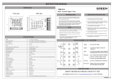
COMPONENT IDENTIFICATION
RUN LED
FRONT VIEW SIDE VIEW
ERR LED
1
2
3
4
5
6
ONLINE LED
SERVICE SW
SERVICE LED
RESET SW
Configuration Jack
1
2
3
4
5
SW2
ON
8
7
6
5
4
3
2
1
SW3
ON
4
3
2
1
ON
8
7
6
5
4
3
2
1
SW1
DIP SW
Euro Type
Connector Terminal
■ ONLINE & SERVICE INDICATOR LED
ONLINE indicator: Red LED
ON: Off-line or no network information (decom-
missioned)
Blinking in approx. 0.5 Hz: On-line (ready to communi-
cate network variables)
Blinking in approx. 5 Hz for 12 sec.: Wink message re-
ceived
SERVICE indicator: Green LED
OFF: Normal operations
Blinking in approx. 0.5 Hz: No network information
ON: Internal program error
■ SERVICE SW
Used to identify the node in L
ONWORKS network configura-
tion.
■ RESET SW
Used to reset the Neuron Chip. Press the switch to reset.
Control functions are halted while completing resetting and
restarting. Confirm no danger before conducting resetting.
■ SIDE DIP SW
(*) Factory setting.
• Data Allocation: SW1, SW2
Data Allocation Type* must be assigned to each I/O module
position to specify how many data areas (four types) are to
be occupied by each.
Two bits from SW1 and SW2 are assigned to each posi-
tion, and data areas can be specified from the module No. 1
through 8. Setting for No. 9 and later modules is identical
to No. 8.
SW ASSIGNMENT MODULE NO.
SW1-1 SW1-2 1
SW1-3 SW1-4 2
SW1-5 SW1-6 3
SW1-7 SW1-8 4
SW2-1 SW2-2 5
SW2-3 SW2-4 6
SW2-5 SW2-6 7
SW2-7 SW2-8 8
SW SETTING DATA ALLOCATION
OFF OFF 1
ON OFF 4
OFF ON 8
ON ON 16
* Refer to the specifications of the related series for the Data
Allocation Type of I/O modules.
• Dual Communication: SW3-1
When two network modules are mounted, one must be
‘Main’ (OFF) network and the other must be ‘Sub’ (ON) net-
work. For single communication, the network module must
always be set to ‘Main’ (OFF).
SW
DUAL COMMUNICATION
MAIN (*) SUB
SW3-1 OFF ON
• Input Error Data: SW3-2
Hold: When the communication from an input module is lost
due to the input module error, the network module holds the
signal and stands by until the communication recovers.
Set to ‘0’: When the communication from an input module
is lost due to the input module error, the network module
outputs ‘0.’
SW
INPUT ERROR DATA
HOLD (*) SET ‘0’
SW3-2 OFF ON
• LED Function: SW3-4
Functions assigned to the front RUN and ERR LEDs can
be selected.
SW3-4
LED FUNCTION
RUN ERR
OFF (*) Green when normal Green when abnormal
ON Red when receiving Red when transmitting
Note: Be sure to set unused SW3-3 to OFF.

R3-NL1
5-2-55, Minamitsumori, Nishinari-ku, Osaka 557-0063 JAPAN
Phone: +81(6)6659-8201 Fax: +81(6)6659-8510 E-mail: info@m-system.co.jp
EM-8427 Rev.7 P. 3 / 9
PC CONFIGURATOR
With configurator software, settings shown below are available.
Refer to the software manual of R3CON for detailed operation.
■ NETWORK MODULE SETTING
PARAMETER AVAILABLE RANGE DEFAULT SETTING
Time (no communication time) 3.0 – 3200.0 (sec.) 3.0 (sec.)
TERMINAL CONNECTIONS
Connect the unit as in the diagram below.
■ EXTERNAL DIMENSIONS unit: mm (inch)
1
2
3
4
5
6
1
2
3
4
5
130 (5.12)
27.5 (1.08)
109 (4.29)
POSITIONING
GUIDE
TERMINAL
COVER
6–M3
SCREW
6.2
(.24)
■ CONNECTION DIAGRAM
INTERNAL POWER
INTERNAL BUS
LONWORKS
CONFIGURATION JACK
JACK
BUS CONNECTOR
1
1
2
3
4
5
4
RUN +
RUN –
RUN CONTACT OUTPUT
2
3
6
U (+)
V (–)
FG
POWER INPUT
*
*
* Not provided with ‘No Power Supply’ type module.
Caution: FG terminal is NOT a protective conductor terminal.
WIRING INSTRUCTIONS
■ M3 SCREW TERMINAL (power input, RUN contact output)
Torque: 0.5 N·m
■ SOLDERLESS TERMINAL
Refer to the drawing below for recommended ring tongue
terminal size. Spade tongue type is also applicable. Solder-
less terminals with insulation sleeve do not fit.
Recommended manufacturer: Japan Solderless Terminal
MFG.Co.Ltd, Nichifu Co.,ltd
Applicable wire size: 0.75 to 1.25 mm
2
12max
6max
3max
4min
3.2 dia.
(mm)
■ EURO TYPE CONNECTOR TERMINAL (LONWORKS)
Applicable wire size: 0.2 to 2.5 mm
2
(AWG24 to 12)
Stripped length: 7 mm

R3-NL1
5-2-55, Minamitsumori, Nishinari-ku, Osaka 557-0063 JAPAN
Phone: +81(6)6659-8201 Fax: +81(6)6659-8510 E-mail: info@m-system.co.jp
EM-8427 Rev.7 P. 4 / 9
COMMUNICATION CABLE CONNECTIONS
HOST PC
L
ON
W
ORKS
R3-NLx
L
ON
W
ORKS
R3-NLx
L
ON
W
ORKS
Terminator
I/O COMBINATIONS
A dedicated Device File for each I/O device depending upon I/O combinations is required to set up the R3-NL1 using an inte-
gration tool such as LonMaker.
On-line download is available for Device Image files at http://www.m-system.co.jp/.
Functional Blocks usable for respective files are not identical to all. Refer to the table below.
■ ANALOG INPUT / OUTPUT
NO. of DATA
DEVICE IMAGE
(APB FILE)
USABLE FUNCTIONAL BLOCKS
INPUT OUTPUT
16 0 R3NL1_1_101.APB NodeObjet, GetValue [0 ... 15] (Can be defined from 0 to 15)
12 4 R3NL1_2_101.APB NodeObjet, GetValue [0 ... 11], SetValue [0 ... 3]
8 8 R3NL1_3_101.APB NodeObjet, GetValue [0 ... 7], SetValue [0 ... 7]
4 12 R3NL1_4_101.APB NodeObjet, GetValue [0 ... 3], SetValue [0 ... 11]
0 16 R3NL1_5_101.APB NodeObjet, SetValue [0 ... 15]
■ DISCRETE INPUT / OUTPUT
NO. of DATA
DEVICE IMAGE
(APB FILE)
USABLE FUNCTIONAL BLOCKS
INPUT OUTPUT
0 48 R3NL1_6_101.APB NodeObjet, R3Do [0 ... 2] (One (1) block can handle 16 contacts.)
48 0 R3NL1_7_101.APB NodeObjet, R3Di [0 ... 2]

R3-NL1
5-2-55, Minamitsumori, Nishinari-ku, Osaka 557-0063 JAPAN
Phone: +81(6)6659-8201 Fax: +81(6)6659-8510 E-mail: info@m-system.co.jp
EM-8427 Rev.7 P. 5 / 9
FUNCTIONAL BLOCKS
■ NODE OBJECT
NodeObject
NVI 1
nviRequest
SNVT_obj_request
NVO 1
nvoStatus
SNVT_obj_status
NVO 2
nvoFileDirectory
SNVT_address
NVO 3
nvoCommErr
SNVT_count
Number of internal
communication errors
NVO 4
nvoCardState
SNVT_state
NVO 5
nvoCardErr
SNVT_state
Each module's error status
Each module status
cpMaxSendTime
cpMinSendTime
: SCPTmaxSendTime
: SCPTminSendTime
Input data sending intervals
Input data minimum sending intervals
Configuration Properties
■ ANALOG INPUT FUNCTIONAL BLOCKS (GetValue [0] through [15])
GetValue [X]
nvoVal
SNVT_lev_percent
or SNVT_temp
or SNVT_state
cpNvoDefValue
cpNvoMaxRnge
cpNvoMinRnge
cpNvoSndDelta
cpNvoType
: (identical to nvoVal)
: (identical to nvoVal)
Default value at the startup
Span (full-scale) value
: (identical to nvoVal) Zero value
: (identical to nvoVal) Value deviation to be sent
: SCPTnvType Network variable type, etc.
Configuration Properties

R3-NL1
5-2-55, Minamitsumori, Nishinari-ku, Osaka 557-0063 JAPAN
Phone: +81(6)6659-8201 Fax: +81(6)6659-8510 E-mail: info@m-system.co.jp
EM-8427 Rev.7 P. 6 / 9
■ ANALOG OUTPUT FUNCTIONAL BLOCKS (SetValue [0] through [15])
SetValue [X]
cpNviDefValue
cpNviMaxRnge
cpNviMinRnge
cpNviType
: (identical to nviVal)
: (identical to nviVal)
Default value at the startup
Span (full-scale) value
: (identical to nviVal) Zero value
: SCPTnvType Network variable type, etc.
Configuration Properties
nviVal
SNVT_lev_percent
or SNVT_state
■ DISCRETE INPUT FUNCTIONAL BLOCKS (R3Di [0] through [2])
R3Di [X]
nvoDich01
:
nvoDich16
SNVT_switch
nvoDiState
SNVT_state
■ DISCRETE OUTPUT FUNCTIONAL BLOCKS (R3Do [0] through [2])
R3Do [X]
nviDoch01
:
nviDoch16
SNVT_switch
nvoDoState
SNVT_state

R3-NL1
5-2-55, Minamitsumori, Nishinari-ku, Osaka 557-0063 JAPAN
Phone: +81(6)6659-8201 Fax: +81(6)6659-8510 E-mail: info@m-system.co.jp
EM-8427 Rev.7 P. 7 / 9
■ NodeObject FUNCTIONAL BLOCKS
NETWORK
VARIABLE
TYPE
{Range}
{Default}
EXPLANATIONS
nviRequest SNVT_obj_request
{Usable RQ
RQ_NORMAL
RQ_REPORT_MASK
RQ_UPDATE_STATUS}
Used for integration tools such as LonMaker.
nvoStatus Used for integration tools such as LonMaker.
• nviRequest RQ_NORMAL
0 is set at nvoStatus.
• nviRequest RQ_REPORT_MASK
report_mask bit is set at nvoStatus.
• nviRequest RQ_UPDATE_STATUE
0 is set at nvoStatus.
• 1 is set at invalid_id when any value other than the above three
types is set at nviRequest.
nvoFileDirectory SNVT_address Used for integration tools such as LonMaker.
nvoCommErr SNVT_count
{0 through 65535}
{0}
Counted in internal communication errors.
Reset to 0 after the count has reached 65535.
nvoCardStatus SNVT_state
{0 or 1}
{0,0,0,0,0,0,0,0,0,0,0,0,0,0,0,0}
Indicates that I/O modules are mounted in each slot.
Bit 0 through bit 15 are applied for slot 1 through 16.
0: Not mounted 1: Mounted
nvoCardErr SNVT_state
{0 or 1}
{0,0,0,0,0,0,0,0,0,0,0,0,0,0,0,0}
Indicates error status for each module/slot.
Bit 0 through bit 15 are applied for slot 1 through 16.
0: Normal 1: Error
CONFIGURATION
PROPERTY
TYPE
{Range}
{Default}
EXPLANATIONS
cpMaxSendTime SCPTmaxSendTime
{0.0 through 6653.4}
{10.0}
Sending time intervals of nvoVal [0 – 15]
Network variables are sent out in this time intervals even when
there is no change in input signals.
cpMinSendTime SCPTminSendTime
{0.0 through 6653.4}
{0.0}
Minimum sending time intervals of nvoVal [0 – 15]
This minimum time intervals is maintained even when the input
signals changes faster than it.

R3-NL1
5-2-55, Minamitsumori, Nishinari-ku, Osaka 557-0063 JAPAN
Phone: +81(6)6659-8201 Fax: +81(6)6659-8510 E-mail: info@m-system.co.jp
EM-8427 Rev.7 P. 8 / 9
■ GetValue [x] FUNCTIONAL BLOCKS
NETWORK
VARIABLE
TYPE
{Range}
{Default}
EXPLANATIONS
nvoVal SNVT_lev_percent
{-163.840 through 163.830}
{Depends on cpNvoDefValue}
• Data acquired from assigned channels.
• Set SNVT_lev_percent for the input types other than discrete or
temperature. Change the network variable type according to the
input type if necessary.
• Configuration Property value must be re-read after the network
variable type is changed. Use “ResyncCP” on the LonMaker.
• For discrete inputs, change the network variable type to SNVT_
state using integration tools such as LonMaker.
Bit 0 through bit 15 of nvoVal are applied for ch. 1 through ch. 16.
• For temperature inputs, change the network variable type to
SNVT_temp using integration tools such as LonMaker.
SNVT_state
{0 OFF (input open)
1 ON (input shorted)}
SNVT_temp
{-274.0 through 3002.7}
CONFIGURATION
PROPERTY
TYPE
{Range}
{Default}
EXPLANATIONS
cpNvoType SCPTnvType
{SNVT_lev_percent
SNVT_state
SNVT_temp}
{SNVT_lev_percent}
nvoVal type
(Use integration tools such as LonMaker to change types.)
cpNvoMaxRnge Identical to nvoVal
{ (Identical to nvoVal) }
{100.0}
nvoVal value at 100% input
Invalid when nvoVal type is either SNVT_state or SNVT_temp.
cpNvoMinRnge Identical to nvoVal
{ (Identical to nvoVal) }
{0.0}
nvoVal value at 0% input
Invalid when nvoVal type is either SNVT_state or SNVT_temp.
cpSendDelta Identical to nvoVal
{ (Identical to nvoVal) }
{0.0}
Network variables are sent out when its deviation exceeds the set
value.
Invalid when nvoVal type is SNVT_state.
■ SetValue [x] FUNCTIONAL BLOCKS
NETWORK
VARIABLE
TYPE
{Range}
{Default}
EXPLANATIONS
nviVal SNVT_lev_percent
{-163.840 through 163.830}
{0}
• Outputs data set to assigned channels.
• Set SNVT_lev_percent for the input types other than discrete.
Change the network variable type according to the output type if
necessary.
• Configuration Property value must be re-read after the network
variable type is changed. Use “ResyncCP” on the LonMaker.
• For discrete outputs, change the network variable type to SNVT_
state using integration tools such as LonMaker.
Bit 0 through bit 15 of nviVal are applied for ch. 1 through ch. 16.
SNVT_state
{0 OFF (output open)
1 ON (output shorted)}
CONFIGURATION
PROPERTY
TYPE
{Range}
{Default}
EXPLANATIONS
cpNviType SCPTnvType
{SNVT_lev_percent
SNVT_state}
{SNVT_lev_percent}
nviVal type
(Use integration tools such as LonMaker to change types.)
cpNviMaxRnge Identical to nviVal
{ (Identical to nviVal) }
{100.0}
nviVal value at 100% output
Invalid when nviVal type is SNVT_state.
cpNviMinRnge Identical to nviVal
{ (Identical to nviVal) }
{0.0}
nviVal value at 0% output
Invalid when nviVal type is SNVT_state.

R3-NL1
5-2-55, Minamitsumori, Nishinari-ku, Osaka 557-0063 JAPAN
Phone: +81(6)6659-8201 Fax: +81(6)6659-8510 E-mail: info@m-system.co.jp
EM-8427 Rev.7 P. 9 / 9
■ R3Di [X] FUNCTIONAL BLOCKS
NETWORK
VARIABLE
TYPE
{Range}
{Default}
EXPLANATIONS
nvoDich01
through
nvoDich16
SNVT_switch
{0 or 1}
{0}
Data acquired from discrete input channels.
nvoDich01 through nvoDich16 are assigned respectively to channels
1 through 16.
nvoDiState SNVT_state
{0 or 1}
{0,0,0,0,0,0,0,0,0,0,0,0,0,0,0,0}
Indicates contact status for each module/slot.
Bit 0 through bit 15 are applied for channels 1 through 16.
■ R3Do [X] FUNCTIONAL BLOCKS
CONFIGURATION
PROPERTY
TYPE
{Range}
{Default}
EXPLANATIONS
nviDoch01
through
nviDoch16
SNVT_switch
{0 or 1}
{0}
Outputs data set to discrete output channels.
nviDoch01 through nviDoch16 are assigned respectively to channels
1 through 16.
nvoDoState SNVT_state
{0 or 1}
{0,0,0,0,0,0,0,0,0,0,0,0,0,0,0,0}
Indicates contact status for each module/slot.
Bit 0 through bit 15 are applied for channels 1 through 16.
TRANSMISSION DATA ASSIGNMENTS
The DIP SW located at the side of the module specifies each I/O module’s data allocation (occupied data area).
Data are assigned in turn from Slot 1, in order of Functional Blocks (Input or GetValue/R3Di first, followed by Output or
SetValue/R3Do).
The 1st output must be the 1st transmitted data in the slot next to the one with the last input data.
[Example 1]
Data Area
Module 1 4 GetValue [0 – 3]
Module 2 4 GetValue [4 – 7]
Module 3 4 SetValue [0]
Module 4 1 SetValue [1]
Module 5 1 SetValue [2]
Module 6 1 SetValue [3]
Module 7 1 SetValue [4]
Module 8 1 SetValue [5]
Module 9 1 SetValue [6]
Module 10 1 SetValue [7]
[Example 2]
Data Area
Module 1 1 GetValue [0]
Module 2 4 GetValue [1 – 4]
Module 3 4 GetValue [5 – 7] The 4th data, Slot 3 is invalid.
Module 4 1 SetValue [0]
Module 5 4 SetValue [1 – 4]
Module 6 4 SetValue [5 – 7] The 4th data, Slot 6 is invalid.
When the data consist of only inputs or outputs, data for the total of 16 Functional Blocks (GetValue [0 – 15] or R3Di [0 – 2],
or SetValue [0 – 15] or R3Do [0 – 2]) are assigned to each module position from Slot 1.
/