3
Installing the Flue Exhaust
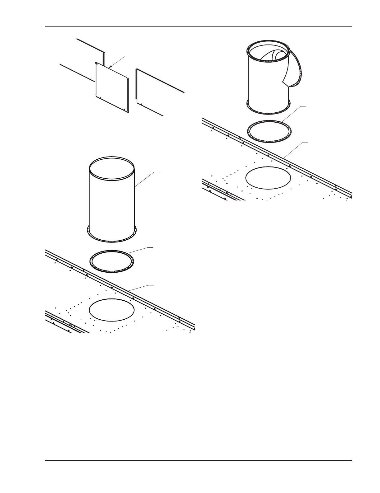
Tee
1. Position the exhaust tee on top of the gasket so
that the fastener holes align to ensure a proper
seal (see Fig. 5).
2. Insert and tighten all stainless steel fasteners in
the base of the tee to secure it to the center sup-
port panel. The fasteners directly below the hori-
zontal exhaust opening will require a flexible
extension to install. (silicone sealant may be nec-
essary to ensure a proper seal).
3. Attach the exhaust pressure tap and tube to the
lower right side of the tee. Ensure that the vent
switch tubing is properly attached to the exhaust
pressure tap.
4. Secure the flue exhaust tee cap (D) and seal gas-
ket (C) to the top of the tee using the stainless
steel hex head fasteners provided.
5. Attach the flue exhaust adapter (B) and seal gas-
ket (C) to the horizontal exhaust pipe opening of
the tee using the stainless steel hex head fasten-
ers provided.
6. Install the rear flue exhaust cover panel (E) where
the rear center cover panel was located (see Fig.
3 and 6).
7. Install the flue exhaust gasket retainer and the flue
exhaust adapter seal gasket (F) (removed in step
3 of the previous section) on the rear flue exhaust
cover panel (see Fig. 6).
8. Install vent piping appropriate for the installation,
including appropriate vent termination.
Center
Support
Panel
Use
existing
seal
Fig. 4: Removing the Flue Exhaust Straight Pipe
Controls and flue exhaust support assembly omitted for clarity
Inside view of rear panels shown. Other components
omitted for clarity.
Fig. 3: Rear Center Cover Panel
Flue Exhaust
Straight Pipe
Exhaust
Seal
Center
Support
Panel
Fig. 5: Installing the Flue Exhaust Tee


