
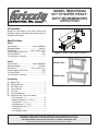
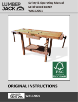
Introduction
Sized to fit the needs of any shop, these work-
benches feature laminated birch construction for
strength and stability.
Specifications
H8361
Construction .............................. Laminated Birch
Shipping Weight .....................................248 lbs.
Dimensions ............................60"L x 30"W x 3"T
Table Height Above Floor ..............................38"
Tail Vise Width ............................................ 14
3
⁄4"
Tail Vise Max. Capacity ....................................7"
H8362
Construction .............................. Laminated Birch
Shipping Weight ......................................315 lbs.
Dimensions .............................72"L x 36"W x 3"T
Table Height Above Floor ..............................38"
Tail Vise Width ............................................ 17
3
⁄4"
Tail Vise Max. Capacity ....................................7"
Inventory
A. Bench Top .................................................. 1
B. Right Side Leg ............................................ 1
C. Left Side Leg .............................................. 1
D. Cross Braces .............................................. 2
E. Tail Vise ...................................................... 1
F. Vise Wood Block ........................................ 1
G. Hardware and Tools (not shown)
—Flat Washers
5
⁄16" .................................. 12
—Machine Screws
5
⁄16"-18 x 4" .................. 8
—Dowel Nuts
5
⁄16"-18 .................................. 8
—Wood Screws
5
⁄16" x 2
1
/2"......................... 4
—Wood Screws #5 x 1
7
⁄16" ......................... 2
—Cotter Pin ................................................ 1
—Hex Wrench 5mm ................................... 1
MODEL H8361/H8362
60"/ 72"SUPER HEAVY-
DUTY WORKBENCHES
INSTRUCTIONS
Figure 1. Model H8361/H8362 inventory.
Figure 2. Model H8361 and H8362.
Model H8361
Model H8362
A
C
D
B
F
E
COPYRIGHT © MAY, 2008 BY GRIZZLY INDUSTRIAL, INC. REVISED APRIL, 2015 (ST)
WARNING: NO PORTION OF THIS MANUAL MAY BE REPRODUCED IN ANY SHAPE
OR FORM WITHOUT THE WRITTEN APPROVAL OF GRIZZLY INDUSTRIAL, INC.
(FOR MACHINES MFD SINCE 5/09) #BL10746 PRINTED IN CHINA

-2-
H8361/H8362 (Mfg. 05/09+)
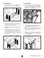
Table Assembly
1. Place eight
5
⁄16"-18 dowel nuts in the holes on
the cross braces, as shown in Figure 3.
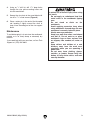
Vise Installation
1. Insert the metal shafts and threaded rod of
the vise through the holes in the vise wood
block and into the vise support block under
the bench top (see Figure 5).
Figure 3. Attaching cross braces and legs.
2. Insert the cross braces into the right and
left legs, and secure with eight
5
⁄16"-18 x 4"
machine screws and flat washers.
Note: Do not fully tighten the fasteners until
instructed.
3. Place the bench top over the legs, align the
mounting holes, and secure with four
5
⁄16" x
2
1
/2" wood screws and
5
⁄16" flat washers, as
shown in Figure 4. Secure all the machine
screws now.
5
⁄16"-18
Dowel Nut
5
⁄16"-18 x 4"
Machine Screw
Right Leg
Cross Brace
Left Leg
Figure 6. Installing vise.
Table Top &
Wood Block Flush
#5 x 1
7
⁄16"
Wood Screws
Vise Plate
Wood Block
Figure 5. Vise threaded into vise support block.
3. Adjust the top of the wood block flush with the
surface of the table using a straightedge, as
shown in Figure 6.
2. Turn the vise handle clockwise until the wood
block (Figure 5) just touches the table.
Note: Do not fully tighten the vise handle;
leave it loose enough so the wood block can
be adjusted in the next step.
Wood Block
Threaded Rod
Metal Shaft
5
⁄16" Flat
Washer
Figure 4. Installing table top.
5
⁄16" x 2
1
⁄2"
Wood Screws
Bench Top
5
⁄16" Flat
Washers
Vise Support Block

H8361/H8362 (Mfg. 05/09+)
-3-
To reduce risk of serious injury when using
this bench:
• Do not apply an unbalanced load that
could result in the workbench tipping
over.
• Do not stand or climb on the
workbench.
• Avoid applying excessive force when
using workbench vise and dogs. Be sure
workpiece is securely locked in place.
• Always wear eye protection.
• Keep your work area clean, uncluttered
and well lit. Do not work on or place
workbench legs on floor surfaces that
are slippery from sawdust, oil, water, or
wax.
• Keep visitors and children at a safe
distance away from the work area,
especially when you are operating a
power tool.
• Do not wear loose clothing, gloves,
neckties, or jewelry. Secure long hair,
button all long sleeve shirts, and wear
non-slip footwear.
4. Using an
1
⁄8" drill bit, drill 1
7
⁄16" deep holes
through the vise plate mounting holes and
into the wood block.
Maintenance
To avoid damaging it, do not store the workbench
outside, or in an overly damp or extremely dry
location.
If you need help with your new item, call our Tech
Support at: (570) 546-9663.
5. Secure the vise plate to the wood block with
two #5 x 1
7
⁄16" wood screws (Figure 6).
6. Place a cotter pin in the end of the threaded
rod, bending it tightly around the shaft to
keep it from threading out of the vise support
block.

-4-
H8361/H8362 (Mfg. 05/09+)
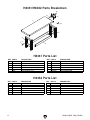
H8361/H8362 Parts Breakdown
H8361 Parts List
H8362 Parts List
1
2
3
4
5
6
6
7
8
9
10
11
12
REF PART # DESCRIPTION REF PART # DESCRIPTION
1 PH8361001 BENCH TOP 7 PH8361007 MACHINE SCREW 5/16"-18 X 4"
2 PH8361002 RIGHT SIDE LEG 8 PH8361008 DOWEL NUT 5/16"-18
3 PH8361003 LEFT SIDE LEG 9 PH8361009 WOOD SCREW 5/16" X 2-1/2"
4 PH8361004 CROSS BRACE 10 PH8361010 WOOD SCREW #5 X 1-7/16"
5 PH8361005 TAIL VISE 11 PH8361011 COTTER PIN
6 PW07 FLAT WASHER 5/16 12 PAW05M HEX WRENCH 5MM
REF PART # DESCRIPTION REF PART # DESCRIPTION
1 PH8362001 BENCH TOP 7 PH8361007 MACHINE SCREW 5/16"-18 X 4"
2 PH8362002 RIGHT SIDE LEG 8 PH8361008 DOWEL NUT 5/16"-18
3 PH8362003 LEFT SIDE LEG 9 PH8361009 WOOD SCREW 5/16" X 2-1/2"
4 PH8362004 CROSS BRACE 10 PH8361010 WOOD SCREW #5 X 1-7/16"
5 PH8362005 TAIL VISE 11 PH8361011 COTTER PIN
6 PW07 FLAT WASHER 5/16 12 PAW05M HEX WRENCH 5MM
-
 1
1
-
 2
2
-
 3
3
-
 4
4


Ask a question and I''ll find the answer in the document
Finding information in a document is now easier with AI
Related papers
-
Grizzly G1867 Owner's manual
-
Grizzly T25101 Owner's manual
-
-
-
-
-
-
-
 Grizzly Industrial G1276 Owner's manual
-

Other documents
-
BENCHPRO KW2472 Installation guide
-
 BENCHPRO HF3672 Operating instructions
-
Unbranded DF3660 Operating instructions
-
 Grizzly Industrial G1867 User manual
-
Hubbell Internal Bracing Operating instructions
-
Unbranded 0895500130 Operating instructions
-
 Lakeland Mills CF1223 Installation guide
-
Lumberjack WB1520D1 Owner's manual
-
 Lumberjack JACK WB1520D1 User manual
-
Harbor Freight Tools 91835 User manual


