Page is loading ...

MODEL G1183/G1276
HEAVY-DUTY
COMBINATION SANDER
OWNER'S MANUAL
WARNING: NO PORTION OF THIS MANUAL MAY BE REPRODUCED IN ANY SHAPE
OR FORM WITHOUT THE WRITTEN APPROVAL OF GRIZZLY INDUSTRIAL, INC.

This manual provides critical safety instructions on the proper setup,
operation, maintenance, and service of this machine/tool. Save this
document, refer to it often, and use it to instruct other operators.
Failure to read, understand and follow the instructions in this manual
may result in fire or serious personal injury—including amputation,
electrocution, or death.
The owner of this machine/tool is solely responsible for its safe use.
This responsibility includes but is not limited to proper installation in
a safe environment, personnel training and usage authorization,
proper inspection and maintenance, manual availability and compre-
hension, application of safety devices, cutting/sanding/grinding tool
integrity, and the usage of personal protective equipment.
The manufacturer will not be held liable for injury or property damage
from negligence, improper training, machine modifications or misuse.
Some dust created by power sanding, sawing, grinding, drilling, and
other construction activities contains chemicals known to the State
of California to cause cancer, birth defects or other reproductive
harm. Some examples of these chemicals are:
• Lead from lead-based paints.
• Crystalline silica from bricks, cement and other masonry products.
• Arsenic and chromium from chemically-treated lumber.
Your risk from these exposures varies, depending on how often you
do this type of work. To reduce your exposure to these chemicals:
Work in a well ventilated area, and work with approved safety equip-
ment, such as those dust masks that are specially designed to filter
out microscopic particles.

Table of Contents
INTRODUCTION ............................................... 2
SECTION 1: SAFETY ....................................... 8
SECTION 2: POWER SUPPLY ...................... 11
SECTION 3: SETUP ....................................... 14
SECTION 4: OPERATIONS ........................... 24
SECTION 5: ACCESSORIES ......................... 30
SECTION 6: MAINTENANCE ......................... 32
SECTION 7: SERVICE ................................... 33
SECTION 8: WIRING ...................................... 37
SECTION 9: PARTS ....................................... 40
WARRANTY AND RETURNS ........................ 45

INTRODUCTION
We stand behind our machines. If you have
any questions or need help, use the information
below to contact us. Before contacting, please get
the serial number and manufacture date of your
machine. This will help us help you faster.
Grizzly Technical Support
1203 Lycoming Mall Circle
Muncy, PA 17756
Phone: (570) 546-9663
Email: [email protected]
We want your feedback on this manual. What did
you like about it? Where could it be improved?
Please take a few minutes to give us feedback.
Grizzly Documentation Manager
P.O. Box 2069
Bellingham, WA 98227-2069
Email: [email protected]
Contact Info
We are proud to offer this manual with your new
machine! We've made every effort to be exact
with the instructions, specifications, drawings,
and photographs of the machine we used when
writing this manual. However, sometimes we still
make an occasional mistake.
Also, owing to our policy of continuous improve-
ment, your machine may not exactly match the
manual. If you find this to be the case, and the dif-
ference between the manual and machine leaves
you in doubt, check our website for the latest
manual update or call technical support for help.
Before calling, find the manufacture date of your
machine by looking at the date stamped into the
machine ID label (see below). This will help us
determine if the manual version you received
matches the manufacture date of your machine.
For your convenience, we post all available man-
uals and manual updates for free on our website
at www.grizzly.com. Any updates to your model
of machine will be reflected in these documents
as soon as they are complete.
Manufacture Date
of Your Machine
Manual Accuracy
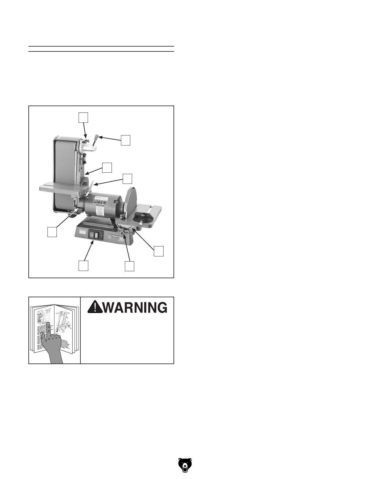
Basic Controls
Figure 5
A. Upper Roller Adjustment Screws:
B. Sanding Belt Quick-Release Tension
Lever:
C. Sanding Belt Table Angle Scale:
D. Sanding Belt Table Lock Lever:
E. Sanding Disc Table Angle Scale:
F. Sanding Disc Table Lock Knob (1 of 2):
G. ON/OFF Switch: ON
OFF
H. Belt Assembly Locking Cap Screw:
Figure 5.
To reduce the risk of
serious injury when using
this machine, read and
understand this entire
manual before beginning
any operations.

The information contained herein is deemed accurate as of 4/26/2011 and represents our most recent product specifications.
Due to our ongoing improvement efforts, this information may not accurately describe items previously purchased.
PAGE 1 OF 3Model G1183
MACHINE DATA
SHEET
Customer Service #: (570) 546-9663 · To Order Call: (800) 523-4777 · Fax #: (800) 438-5901
MODEL G1183 COMBINATION SANDER 6" X 48" BELT 12"
DISC 3450 RPM
Product Dimensions:
Weight.............................................................................................................................................................. 144 lbs.
Width (side-to-side) x Depth (front-to-back) x Height........................................................ 32-1/2 x 16-1/2 x 29-1/2 in.
Footprint (Length x Width)..................................................................................................................... 16-1/2 x 14 in.
Shipping Dimensions:
Type............................................................................................................................................................. Cardboard
Content........................................................................................................................................................... Machine
Weight.............................................................................................................................................................. 148 lbs.
Length x Width x Height....................................................................................................................... 30 x 28 x 18 in.
Electrical:
Power Requirement................................................................................................. 110V/220V, Single-Phase, 60 Hz
Prewired Voltage.................................................................................................................................................. 110V
Full-Load Current Rating....................................................................................................... 12A at 110V, 6A at 220V
Minimum Circuit Size.............................................................................................................................................. 15A
Switch....................................................................................................................................................... Push Button
Switch Voltage..................................................................................................................................................... 110V
Cord Length............................................................................................................................................................ 5 ft.
Cord Gauge................................................................................................................................................... 14 gauge
Plug Included.......................................................................................................................................................... Yes
Included Plug Type...................................................................................................................... NEMA 5-15 for 110V
Recommended Plug/Outlet Type................................................................................................ NEMA 6-15 for 220V
Motors:
Main
Type.................................................................................................................. TEFC Capacitor Start Induction
Horsepower................................................................................................................................................ 1 HP
Voltage................................................................................................................................................ 110/220V
Prewired..................................................................................................................................................... 110V
Phase....................................................................................................................................................... Single
Amps......................................................................................................................................................... 12/6A
Speed................................................................................................................................................ 3450 RPM
Cycle......................................................................................................................................................... 60 Hz
Number of Speeds............................................................................................................................................ 1
Power Transfer ............................................................................................................................... Direct Drive
Bearings................................................................................................. Shielded and Permanently Lubricated

The information contained herein is deemed accurate as of 4/26/2011 and represents our most recent product specifications.
Due to our ongoing improvement efforts, this information may not accurately describe items previously purchased.
PAGE 2 OF 3Model G1183
Main Specifications:
Table Info
Table Tilt............................................................................................ Belt -20 to +45 deg, Disc -45 to +45 deg.
Miter Gauge Slot Width............................................................................................................................. 3/4 in.
Miter Gauge Slot Height........................................................................................................................... 3/8 in.
Belt Table Length................................................................................................................................ 12-1/2 in.
Belt Table Width.......................................................................................................................................... 7 in.
Belt Table Thickness............................................................................................................................. 1-1/4 in.
Disc Table Length................................................................................................................................ 16-1/2 in.
Disc Table Width.......................................................................................................................................... 7 in.
Disc Table Thickness................................................................................................................................... 1 in.
Belt Info
Sanding Belt Width...................................................................................................................................... 6 in.
Sanding Belt Length.................................................................................................................................. 48 in.
Sanding Belt Speed........................................................................................................................... 5000 FPM
Belt Arm Tilt....................................................................................................................................... 0 - 90 deg.
Height Belt Arm Horizontal.................................................................................................................. 14-1/2 in.
Height Belt Arm Vertical...................................................................................................................... 29-1/2 in.
Belt Release................................................................................................................................ Quick Release
Drive Roller Type................................................................................................................................ Aluminum
Drive Roller Length................................................................................................................................ 6-1/4 in.
Drive Wheel Diameter.................................................................................................................................. 5 in.
Idler Roller Type................................................................................................................................. Aluminum
Idler Roller Length................................................................................................................................. 6-1/4 in.
Idler Roller Diameter.............................................................................................................................. 3-1/2 in.
Spindle Info
Arbor Size................................................................................................................................................. 3/4 in.
Total Arbor Length....................................................................................................................................... 6 in.
Disc Info
Sanding Disc Diameter.............................................................................................................................. 12 in.
Sanding Disc Speed.......................................................................................................................... 3450 RPM
Platen Info
Platen Type......................................................................................................................................... Cast Iron
Platen Length...................................................................................................................................... 14-1/2 in.
Platen Width................................................................................................................................................ 6 in.
Platen Travel............................................................................................................................................. 1/4 in.
Construction
Base........................................................................................................................................... Cast Aluminum
Table....................................................................................................................................... Ground Cast Iron
Frame......................................................................................................................................... Cast Aluminum
Disc..................................................................................................................................................... Aluminum
Miter Gauge................................................................................................. Die Cast Aluminum/Aluminum Bar
Paint......................................................................................................................................................... Epoxy
Other
No. Of Dust Ports............................................................................................................................................. 2
Dust Port Size.................................................................................................................................... 2-1/2, 3 in.
Other Specifications:
ISO Factory .................................................................................................................................................. ISO 9001
Country Of Origin ............................................................................................................................................. Taiwan
Warranty ........................................................................................................................................................... 1 Year
Serial Number Location ......................................................................................................... Machine Label on Motor
Assembly Time ........................................................................................................................................... 45 minutes

The information contained herein is deemed accurate as of 4/26/2011 and represents our most recent product specifications.
Due to our ongoing improvement efforts, this information may not accurately describe items previously purchased.
PAGE 1 OF 3Model G1276
MACHINE DATA
SHEET
Customer Service #: (570) 546-9663 · To Order Call: (800) 523-4777 · Fax #: (800) 438-5901
MODEL G1276 COMBINATION SANDER 6" X 48" BELT 12"
DISC 1725 RPM
Product Dimensions:
Weight.............................................................................................................................................................. 145 lbs.
Width (side-to-side) x Depth (front-to-back) x Height........................................................ 32-1/2 x 16-1/2 x 29-1/2 in.
Footprint (Length x Width)............................................................................................................................ 17 x 14 in.
Shipping Dimensions:
Type............................................................................................................................................................. Cardboard
Content........................................................................................................................................................... Machine
Weight.............................................................................................................................................................. 150 lbs.
Length x Width x Height....................................................................................................................... 30 x 28 x 18 in.
Electrical:
Power Requirement................................................................................................. 110V/220V, Single-Phase, 60 Hz
Prewired Voltage.................................................................................................................................................. 110V
Full-Load Current Rating....................................................................................................... 12A at 110V, 6A at 220V
Minimum Circuit Size.............................................................................................................................................. 15A
Switch....................................................................................................................................................... Push Button
Switch Voltage..................................................................................................................................................... 110V
Cord Length............................................................................................................................................................ 5 ft.
Cord Gauge................................................................................................................................................... 14 gauge
Plug Included.......................................................................................................................................................... Yes
Included Plug Type...................................................................................................................... NEMA 5-15 for 110V
Recommended Plug/Outlet Type................................................................................................ NEMA 6-15 for 220V
Motors:
Main
Type.................................................................................................................. TEFC Capacitor Start Induction
Horsepower................................................................................................................................................ 1 HP
Voltage................................................................................................................................................ 110/220V
Prewired..................................................................................................................................................... 110V
Phase....................................................................................................................................................... Single
Amps......................................................................................................................................................... 12/6A
Speed................................................................................................................................................ 1725 RPM
Cycle......................................................................................................................................................... 60 Hz
Number of Speeds............................................................................................................................................ 1
Power Transfer ............................................................................................................................... Direct Drive
Bearings................................................................................................. Shielded and Permanently Lubricated

The information contained herein is deemed accurate as of 4/26/2011 and represents our most recent product specifications.
Due to our ongoing improvement efforts, this information may not accurately describe items previously purchased.
PAGE 2 OF 3Model G1276
Main Specifications:
Table Info
Table Tilt............................................................................................ Belt -20 to +45 deg; Disc -45 to +45 deg.
Miter Gauge Slot Width............................................................................................................................. 3/4 in.
Miter Gauge Slot Height........................................................................................................................... 3/8 in.
Belt Table Length................................................................................................................................ 12-1/2 in.
Belt Table Width.......................................................................................................................................... 7 in.
Belt Table Thickness............................................................................................................................. 1-1/4 in.
Disc Table Length................................................................................................................................ 16-1/2 in.
Disc Table Width.......................................................................................................................................... 7 in.
Disc Table Thickness................................................................................................................................... 1 in.
Belt Info
Sanding Belt Width...................................................................................................................................... 6 in.
Sanding Belt Length.................................................................................................................................. 48 in.
Sanding Belt Speed........................................................................................................................... 2500 FPM
Belt Arm Tilt....................................................................................................................................... 0 - 90 deg.
Height Belt Arm Horizontal.................................................................................................................. 14-1/2 in.
Height Belt Arm Vertical...................................................................................................................... 29-1/2 in.
Belt Release................................................................................................................................ Quick Release
Drive Roller Type................................................................................................................................ Aluminum
Drive Roller Length................................................................................................................................ 6-1/4 in.
Drive Wheel Diameter.................................................................................................................................. 5 in.
Idler Roller Type................................................................................................................................. Aluminum
Idler Roller Length................................................................................................................................. 6-1/4 in.
Idler Roller Diameter.............................................................................................................................. 3-1/2 in.
Spindle Info
Arbor Size................................................................................................................................................. 3/4 in.
Total Arbor Length....................................................................................................................................... 6 in.
Disc Info
Sanding Disc Diameter.............................................................................................................................. 12 in.
Sanding Disc Speed.......................................................................................................................... 1725 RPM
Platen Info
Platen Type.......................................................................................................................................... Cast Iron
Platen Length...................................................................................................................................... 14-1/2 in.
Platen Width................................................................................................................................................ 6 in.
Platen Travel............................................................................................................................................. 1/4 in.
Construction
Base........................................................................................................................................... Cast Aluminum
Table....................................................................................................................................... Ground Cast Iron
Frame......................................................................................................................................... Cast Aluminum
Disc..................................................................................................................................................... Aluminum
Miter Gauge................................................................................................. Die Cast Aluminum/Aluminum Bar
Paint......................................................................................................................................................... Epoxy
Other
No. Of Dust Ports............................................................................................................................................. 2
Dust Port Size.................................................................................................................................... 2-1/2, 3 in.
Other Specifications:
ISO Factory .................................................................................................................................................. ISO 9001
Country Of Origin ............................................................................................................................................. Taiwan
Warranty ........................................................................................................................................................... 1 Year
Serial Number Location ......................................................................................................... Machine Label on Motor
Assembly Time ........................................................................................................................................... 45 minutes
For Your Own Safety, Read Instruction
Manual Before Operating this Machine
The purpose of safety symbols is to attract your attention to possible hazardous conditions.
This manual uses a series of symbols and signal words intended to convey the level of impor-
tance of the safety messages. The progression of symbols is described below. Remember that
safety messages by themselves do not eliminate danger and are not a substitute for proper
accident prevention measures.
WEARING PROPER APPAREL. Do not wear
clothing, apparel, or jewelry that can become
entangled in moving parts. Always tie back or
cover long hair. Wear non-slip footwear to avoid
accidental slips which could cause a loss of work-
piece control.
HEARING PROTECTION. Always wear hear-
ing protection when operating or observiing loud
machinery. Extended exposure to this noise
without hearing protection can cause permanent
hearing loss.
MENTAL ALERTNESS. Be mentally alert when
running machinery. Never operate under the
influence of drugs or alcohol, when tired, or when
distracted.
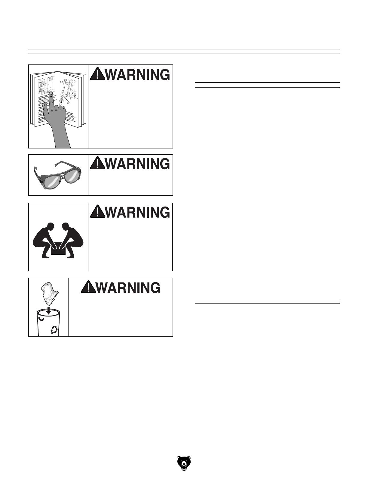
OWNER’S MANUAL. Read and understand
this owner’s manual BEFORE using machine.
Untrained users can be seriously hurt.
EYE PROTECTION. Always wear ANSI-approved
safety glasses or a face shield when operating or
observing machinery to reduce the risk of eye
injury or blindness from flying particles. Everyday
eyeglasses are not approved safety glasses.
HAZARDOUS DUST. Dust created while using
machinery may cause cancer, birth defects, or
long-term respiratory damage. Be aware of dust
hazards associated with each workpiece material,
and always wear a NIOSH-approved respirator to
reduce your risk.
Indicates a potentially hazardous situation which, if not avoided,
MAY result in minor or moderate injury. It may also be used to alert
against unsafe practices.
Indicates a potentially hazardous situation which, if not avoided,
COULD result in death or serious injury.
Indicates an imminently hazardous situation which, if not avoided,
WILL result in death or serious injury.
This symbol is used to alert the user to useful information about
proper operation of the machine.
NOTICE
Safety Instructions for Machinery
SECTION 1: SAFETY

DISCONNECTING POWER SUPPLY.Alwaysdis-
connect machine from power supply before ser-
vicing, adjusting, or changing cutting tools (bits,
blades,cutters, etc.). Makesure switch isin OFF
positionbeforereconnectingtoavoidanunexpect-
edorunintentionalstart.
APPROVED OPERATION. Untrained operators
can be seriously hurt by machinery. Only allow
trained or properly supervised people to use
machine. When machine is not being used, dis-
connect power, remove switch keys, or lock-out
machinetopreventunauthorizeduse—especially
aroundchildren.Makeworkshopkidproof!
DANGEROUS ENVIRONMENTS. Do not use
machinery in wet or rainy locations, cluttered
areas, around flammables,or in poorly-lit areas.
Keep work area clean, dry, and well-lighted to
minimizeriskofinjury.
ONLY USE AS INTENDED. Only use machine
for its intended purpose. Never modify or alter
machineforapurposenotintendedbythemanu-
facturerorseriousinjurymayresult!
USE RECOMMENDED ACCESSORIES.Consult
thisowner’smanualorthemanufacturerforrec-
ommended accessories. Using improper acces-
sorieswillincreasetheriskofseriousinjury.
CHILDREN & BYSTANDERS. Keep children
andbystandersasafedistanceawayfromwork
area.Stopusingmachineifchildrenorbystand-
ersbecomeadistraction.
REMOVE ADJUSTING TOOLS. Never leave
adjustmenttools,chuckkeys,wrenches,etc.inor
onmachine—especiallynearmovingparts.Verify
removalbeforestarting!
SECURING WORKPIECE. When required, use
clampsorvisestosecureworkpiece.A secured
workpieceprotectshandsandfreesbothofthem
tooperatethemachine.
FEED DIRECTION.Unlessotherwisenoted,feed
work against the rotation of blades or cutters.
Feedinginthesamedirectionofrotationmaypull
yourhandintothecut.
FORCING MACHINERY.Donotforcemachine.
Itwill do the jobsafer and better atthe rate for
whichitwasdesigned.
GUARDS & COVERS. Guards and covers can
protect you from accidental contact with moving
parts or flying debris. Make sure they are prop-
erlyinstalled,undamaged, andworkingcorrectly
beforeusingmachine.
NEVER STAND ON MACHINE.Seriousinjuryor
accidental contact with cutting tool may occur if
machineistipped.Machinemaybedamaged.
STABLE MACHINE. Unexpectedmovementdur-
ingoperationsgreatlyincreasestheriskofinjury
and loss of control. Verify machines are stable/
secure and mobile bases (if used) are locked
beforestarting.
AWKWARD POSITIONS. Keep proper footing
andbalanceatalltimeswhenoperatingmachine.
Donotoverreach!Avoidawkwardhandpositions
that make workpiece control difficult or increase
theriskofaccidentalinjury.
UNATTENDED OPERATION. Never leave
machinerunningwhileunattended.Turnmachine
offandensureallmovingpartscompletelystop
beforewalkingaway.
MAINTAIN WITH CARE.Followallmaintenance
instructions and lubrication schedules to keep
machineingoodworkingcondition.Animproperly
maintainedmachinemayincreasetheriskofseri-
ousinjury.
CHECK DAMAGED PARTS. Regularly inspect
machine for damaged parts, loose bolts, mis-
adjusted or mis-aligned parts, binding, or any
other conditions that may affect safe operation.
Alwaysrepairorreplacedamagedormis-adjust-
edpartsbeforeoperatingmachine.
EXPERIENCING DIFFICULTIES. If at any time
you are experiencing difficulties performing the
intended operation, stop using the machine!
Contact our Technical Support Department at
(570)546-9663.

Additional Safety for Combination Sanders
WORKPIECE INSPECTION.
FEEDING WORKPIECE.
SANDPAPER CONDITION.
IN-RUNNING NIP POINTS.
WORKPIECE INTEGRITY.
DISC DIRECTION.
AVOIDING ENTANGLEMENT.
HAND PLACEMENT.
MINIMUM STOCK DIMENSION.
WORKPIECE SUPPORT.
SANDING DUST.
Like all machinery there is potential danger when operating this machine. Accidents are fre-
quently caused by lack of familiarity or failure to pay attention. Use this machine with respect
and caution to decrease the risk of operator injury. If normal safety precautions are overlooked
or ignored, serious personal injury may occur.

SECTION 2: POWER SUPPLY
Availability
Before installing the machine, consider the avail-
ability and proximity of the required power supply
circuit. If an existing circuit does not meet the
requirements for this machine, a new circuit must
be installed. To minimize the risk of electrocu-
tion, fire, or equipment damage, installation work
and electrical wiring must be done by a qualified
electrician in accordance with all applicable codes
and standards.
Electrocution, fire, or
equipment damage may
occur if machine is not
correctly grounded and
connected to the power
supply.
Full-Load Current Rating
The full-load current rating is the amperage a
machine draws at 100% of the rated output power.
On machines with multiple motors, this is the
amperage drawn by the largest motor or sum of all
motors and electrical devices that might operate
at one time during normal operations.
Full-Load Current Rating at 110V ...... 12 Amps
Full-Load Current Rating at 220V ....... 6 Amps
The full-load current is not the maximum amount
of amps that the machine will draw. If the machine
is overloaded, it will draw additional amps beyond
the full-load rating.
If the machine is overloaded for a sufficient length
of time, damage, overheating, or fire may result—
especially if connected to an undersized circuit.
To reduce the risk of these hazards, avoid over-
loading the machine during operation and make
sure it is connected to a power supply circuit that
meets the requirements in the following section.
For your own safety and protection of
property, consult a qualified electrician if
you are unsure about wiring practices or
electrical codes in your area.
Note: The circuit requirements listed in this man-
ual apply to a dedicated circuit—where only one
machine will be running at a time. If this machine
will be connected to a shared circuit where mul-
tiple machines will be running at the same time,
consult a qualified electrician to ensure that the
circuit is properly sized for safe operation.
A power supply circuit includes all electrical
equipment between the breaker box or fuse panel
in the building and the machine. The power sup-
ply circuit used for this machine must be sized to
safely handle the full-load current drawn from the
machine for an extended period of time. (If this
machine is connected to a circuit protected by
fuses, use a time delay fuse marked D.)
Circuit Information
Circuit Requirements for 220V
Nominal Voltage .............................. 220V/240V
Cycle ..........................................................60 Hz
Phase ........................................... Single-Phase
Circuit Rating ...................................... 15 Amps
Plug/Receptacle ............................. NEMA 6-15
This machine can be converted to operate on a
220V power supply (refer to Voltage Conversion
instructions). This power supply must have a veri-
fied ground and meet the following requirements:
This machine is prewired to operate on a 110V
power supply circuit that has a verified ground and
meets the following requirements:
Circuit Requirements for 110V
Nominal Voltage ............................... 110V/120V
Cycle ..........................................................60 Hz
Phase ........................................... Single-Phase
Circuit Rating ...................................... 15 Amps
Plug/Receptacle ............................. NEMA 5-15
Improper connection of the equipment-grounding
wire can result in a risk of electric shock. The
wire with green insulation (with or without yellow
stripes) is the equipment-grounding wire. If repair
or replacement of the power cord or plug is nec-
essary, do not connect the equipment-grounding
wire to a live (current carrying) terminal.
Check with a qualified electrician or service per-
sonnel if you do not understand these grounding
requirements, or if you are in doubt about whether
the tool is properly grounded. If you ever notice
that a cord or plug is damaged or worn, discon-
nect it from power, and immediately replace it with
a new one.
Grounding Requirements
This machine MUST be grounded. In the event
of certain malfunctions or breakdowns, grounding
reduces the risk of electric shock by providing a
path of least resistance for electric current.
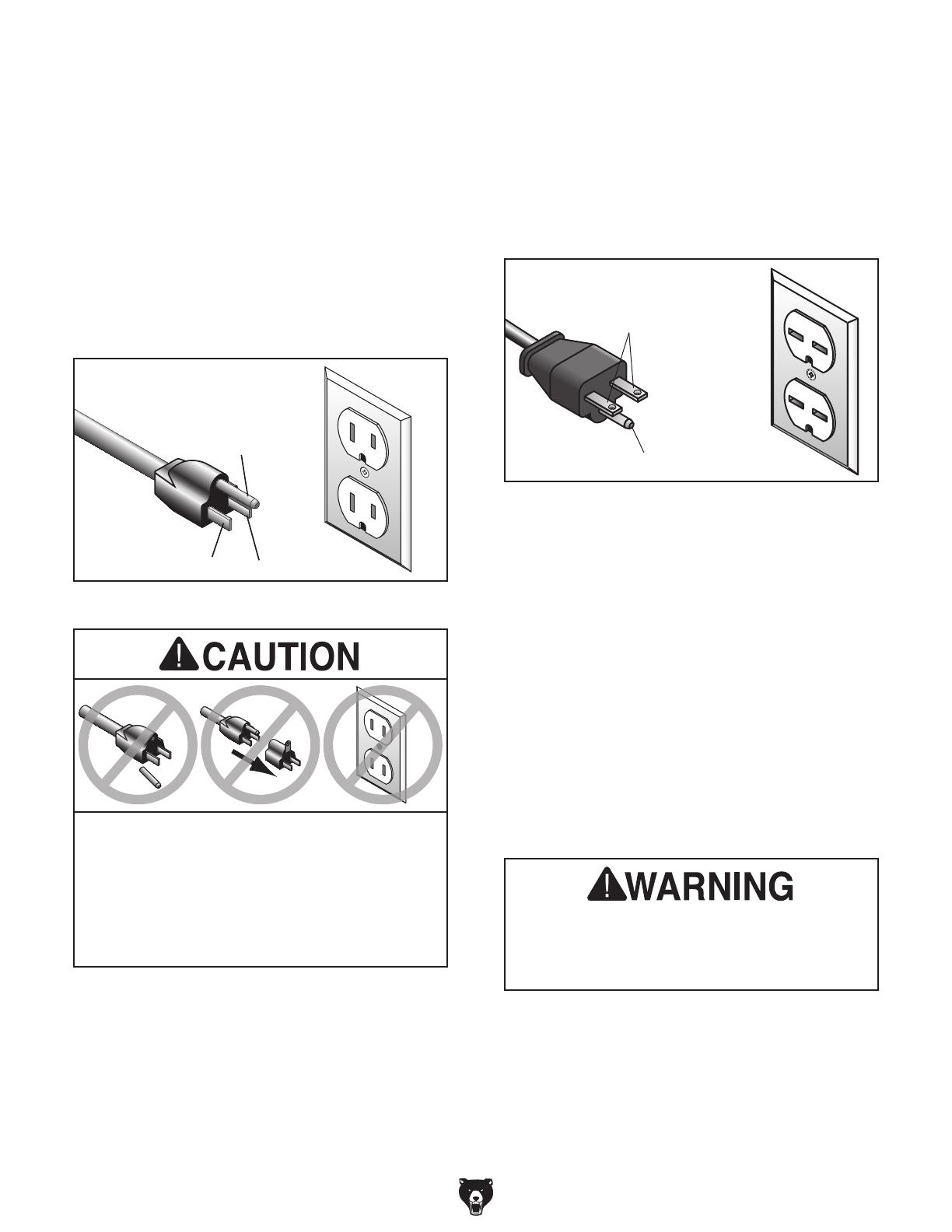
Figure 6.
Grounding Prong
Neutral Hot
5-15 PLUG
GROUNDED
5-15 RECEPTACLE
Figure 7.
Grounding Prong
Current Carrying Prongs
6-15 PLUG
GROUNDED
6-15 RECEPTACLE
Serious injury could occur if you connect
the machine to power before completing the
setup process. DO NOT connect to power
until instructed later in this manual.
For 110V operation: This machine is equipped
with a power cord that has an equipment-ground-
ing wire and a grounding plug (see following fig-
ure). The plug must only be inserted into a match-
ing receptacle (outlet) that is properly installed
and grounded in accordance with all local codes
and ordinances.
SHOCK HAZARD!
Two-prong outlets do not meet the grounding
requirements for this machine. Do not modify
or use an adapter on the plug provided—if
it will not fit the outlet, have a qualified
electrician install the proper outlet with a
verified ground.
For 220V operation: The plug specified under
“Circuit Requirements for 220V” on the previous
page has a grounding prong that must be attached
to the equipment-grounding wire on the included
power cord. The plug must only be inserted into
a matching receptacle (see following figure) that
is properly installed and grounded in accordance
with all local codes and ordinances.

Extension Cords
We do not recommend using an extension cord
with this machine. If you must use an extension
cord, only use it if absolutely necessary and only
on a temporary basis.
Extension cords cause voltage drop, which may
damage electrical components and shorten motor
life. Voltage drop increases as the extension cord
size gets longer and the gauge size gets smaller
(higher gauge numbers indicate smaller sizes).
Any extension cord used with this machine must
contain a ground wire, match the required plug
and receptacle, and meet the following require-
ments:
Minimum Gauge Size ...........................12 AWG
Maximum Length (Shorter is Better).......50 ft.
Voltage Conversion
Page 11
To convert the machine to 220V:
1.
2.
3.
Page 39
Note: If the diagram included on the motor
conflicts with the one in this manual, the
motor may have changed since the manual
was printed. Use the diagram provided on the
motor.
Wear safety glasses dur-
ing the entire setup pro-
cess!
This machine presents
serious injury hazards
to untrained users. Read
through this entire manu-
al to become familiar with
the controls and opera-
tions before starting the
machine!
SECTION 3: SETUP
Description Qty
Needed for Setup
please imme-
diately call Customer Service at (570) 546-9663
for advice.
Otherwise, filing a freight claim can be difficult.
Unpacking
This machine and its com-
ponents are very heavy.
Get lifting help or use
power lifting equipment
such as a forklift to move
heavy items.
SUFFOCATION HAZARD!
Keep children and pets away
from plastic bags or packing
materials unpacked with this
machine. Discard immediately.
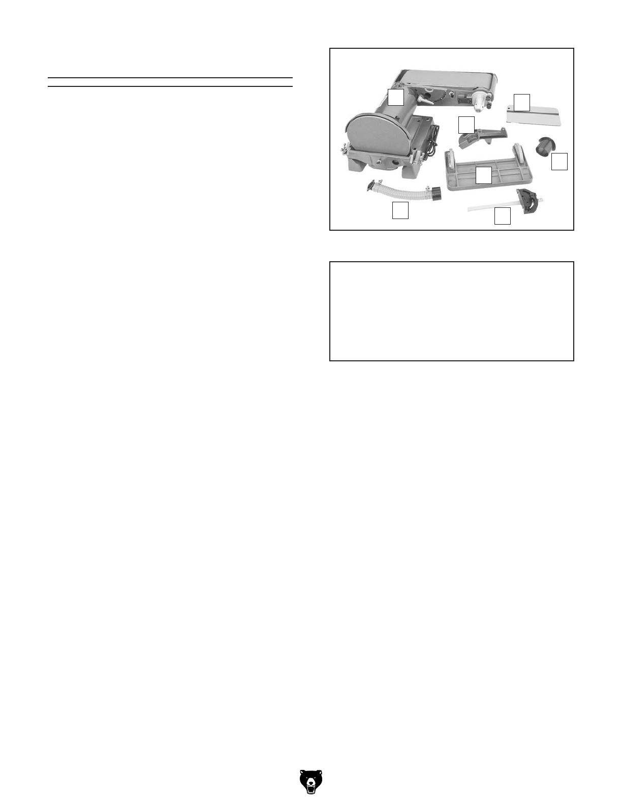
Inventory
The following is a description of the main compo-
nents shipped with your machine. Lay the compo-
nents out to inventory them.
If any non-proprietary parts are missing (e.g. a
nut or a washer), we will gladly replace them; or
for the sake of expediency, replacements can be
obtained at your local hardware store.
NOTICE
If you cannot find an item on this list, check
the mounting location on the machine or the
packaging materials. Sometimes parts are
pre-installed for shipping, or they become
hidden by packaging materials.
Shipping Inventory: (Figure 8) Qty
A.
B.
C.
D.
E.
F.
G.
H.
Figure 8.

The unpainted surfaces of your machine are
coated with a heavy-duty rust preventative that
prevents corrosion during shipment and storage.
This rust preventative works extremely well, but it
will take a little time to clean.
Be patient and do a thorough job cleaning your
machine. The time you spend doing this now will
give you a better appreciation for the proper care
of your machine's unpainted surfaces.
There are many ways to remove this rust preven-
tative, but the following steps work well in a wide
variety of situations. Always follow the manufac-
turer’s instructions with any cleaning product you
use and make sure you work in a well-ventilated
area to minimize exposure to toxic fumes.
Before cleaning, gather the following:
• Disposable Rags
• Cleaner/degreaser (WD•40 works well)
• Safety glasses & disposable gloves
• Plastic paint scraper (optional)
Basic steps for removing rust preventative:
1. Put on safety glasses.
2. Coat the rust preventative with a liberal
amount of cleaner/degreaser, then let it soak
for 5–10 minutes.
3. Wipe off the surfaces. If your cleaner/degreas-
er is effective, the rust preventative will wipe
off easily. If you have a plastic paint scraper,
scrape off as much as you can first, then wipe
off the rest with the rag.
4. Repeat Steps 2–3 as necessary until clean,
then coat all unpainted surfaces with a quality
metal protectant to prevent rust.
Gasoline or products
with low flash points can
explode or cause fire if
used to clean machin-
ery. Avoid cleaning with
these products.
Many cleaning solvents
are toxic if concentrat-
ed amounts are inhaled.
Only work in a well-venti-
lated area.
NOTICE
Avoid chlorine-based solvents, such as
acetone or brake parts cleaner, that may
damage painted surfaces. Test all cleaners
in an inconspicuous area before using to
make sure they will not damage paint.
Cleanup

Site Considerations
Figure 9.
32"
32"
Dust
Hose
Dust
Hose
Weight Load
Refer to the Machine Data Sheet for the weight
of your machine. Make sure that the surface upon
which the machine is placed will bear the weight
of the machine, additional equipment that may be
installed on the machine, and the heaviest work-
piece that will be used. Additionally, consider the
weight of the operator and any dynamic loading
that may occur when operating the machine.
Space Allocation
Consider the largest size of workpiece that will
be processed through this machine and provide
enough space around the machine for adequate
operator material handling or the installation of
auxiliary equipment. With permanent installations,
leave enough space around the machine to open
or remove doors/covers as required by the main-
tenance and service described in this manual.
See below for required space allocation.
Physical Environment
The physical environment where your machine
is operated is important for safe operation and
the longevity of its components. For best results,
operate this machine in a dry environment that is
free from excessive moisture, hazardous chemi-
cals, airborne abrasives, or extreme conditions.
Extreme conditions for this type of machinery are
generally those where the ambient temperature
range exceeds 41°–104°F; the relative humidity
range exceeds 20–95% (non-condensing); or the
environment is subject to vibration, shocks, or
bumps.
Electrical Installation
Place this machine near an existing power source.
Make sure all power cords are protected from
traffic, material handling, moisture, chemicals,
or other hazards. Make sure to leave access to
a means of disconnecting the power source or
engaging a lockout/tagout device.
Lighting
Lighting around the machine must be adequate
enough that operations can be performed safely.
Shadows, glare, or strobe effects that may distract
or impede the operator must be eliminated.
Children or untrained people
may be seriously injured by
this machine. Only install in an
access restricted location.
AssemblyMounting
Machine Base
Workbench
Bolt
Flat Washer
Flat Washer
Lock Washer
Hex Nut
Figure 10.
Machine Base
Workbench
Lag Screw
Flat Washer
Figure 11.
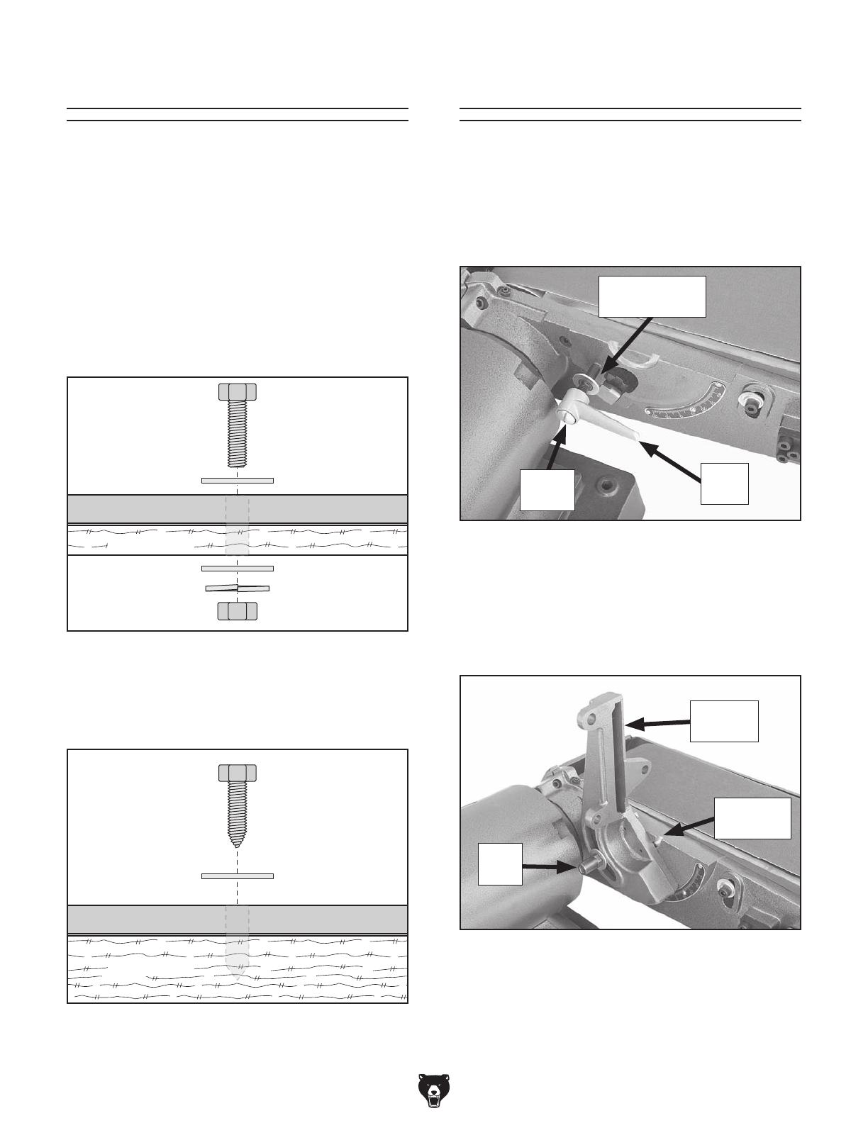
To assemble the sander:
1.
Figure 12
2.
Step 1Figure 13
3.
Figure 12.
Figure 13.
/