Page is loading ...

Introduction
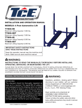
The Model H6229 12 Ton A-Frame Shop Press
(Figure 1) features 12 tons of pressure to handle
forming, bending, and bearing installation.
The Model H6229 was carefully packed when
it left our warehouse. If you discover this shop
press is damaged after you have signed for deliv
-
ery, please immediately call Customer Service at
(570) 546-9663
for advice. Save the containers
and all packing materials for possible inspec
-
tion by the carrier or its agent. Otherwise, filing a
freight claim can be difficult.
When completely satisfied with the condition of
your shipment, inventory the contents.
Figure 2 -
Inventory.
A. Header ........................................................ 1
B. Springs ....................................................... 2
C. Header Supports ........................................ 4
D. Uprights ...................................................... 2
E. Jack Plate ................................................... 1
F. Angle Braces .............................................. 4
G. Base Supports ............................................ 2
H. Support Rods ............................................. 2
I. Spreader ..................................................... 1
J. Crossbeams ............................................... 2
K. Table Plates ............................................... 2
L. Table .......................................................... 1
M. Hydraulic Jack ............................................ 1
N. Jack Handle ................................................ 1
O. Bolt Bag ...................................................... 1
—Hex Bolts M14-2 X 45 ............................
2
—Flat Washers 14mm ...............................
6
—Hex Nuts M14-2 ......................................
6
—Hex Bolts M14-2 X 110 ..........................
2
—Hex Bolts M14-2 X 95 ............................
2
—Hex Bolts M8-1.25 X 25 .......................
12
—Lock Washers 8mm ..............................
12
—Hex Nuts M8-1.25 ................................
12
—Spacers 8mm ..........................................
4
Figure 2. Inventory.
12 Ton A-Frame
Shop Press
MODEL H6229
INSTRUCTION SHEET
Figure 1. Model H6229.
Always use ANSI approved
safety glasses when operat
-
ing machinery
.
B
E
O
K
N
M
A
H
L
J
C
D
I
G
F F
This Shop Press is not a toy. DO NOT allow
children to use this press. Serious injury
may occur if this press is used incorrectly.

1. Place the spreader between the uprights and
thread M8-1.25 x 25 hex bolts through the
holes in the spreader, the uprights, and the
base supports. Secure with 8mm lock wash
-
ers and hex nuts (Figure 3
).
ASSEMBLY
Figure 4. Table placement.
4. Align a crossbeam with the second set of
holes from the top of the uprights and secure
it with M14-2 x 95 hex bolts, washers, and
hex nuts.
5. Align the second crossbeam with the top
holes in the uprights. Slide a header support
onto a M14-2 x 110 hex bolt and thread the
hex bolt through the header and crossbeam
(Figure 5).
Figure 5. Attaching the crossbeam.
6. Place another header support over the hex
bolt and secure with a 14mm washer and
M14-2 hex nut.
7. Repeat steps 6–7 for the other end of the
crossbeam.
8. Slide the rod of the jack plate down through
the holes in the crossbeams (Figure 6
).
Figure 6. Jack plate installation.
2. Attach the angle braces to the base supports
with M8-1.25 x 25 hex bolts, 8mm lock wash
-
ers, and hex nuts. Place a spacer between
the top of the angle braces and the uprights,
and secure with the remaining 8mm hex
bolts, washers, and hex nuts (Figure 3
).
3. Slide the table over the frame and insert the
support rods (Figure 4
).
Figure 3. Installing the base supports.
Base Support
Spreader
Table
Spacer
Support Rods
Angle Braces

1. Lift the table until there is just enough room
for the table plates and workpiece between
the table and the jack plate rod. Place the
support rods through the uprights and lower
the table onto the support rods.
2. Place the table plates on the table and put
the workpiece on the table plates.
OPERATIONS
9. Slide the header between the header sup-
ports, and thread the M14-2 x 45 hex bolts
through the supports and the header. Secure
the hex bolts with 14mm flat washers and
M14-2 hex nuts (Figure 7
).
Figure 7. Header installation.
10. Hang the springs from the hooks in the head-
er, lift up the jack plate, and hook the springs
through the holes in the jack plate.
11. Press the jack plate down, and slide the
hydraulic jack between the jack plate and the
header (Figure 8).
Figure 8. Jack installation.
Keep hands away from the
pressure head and out of
support rod holes
.
Always center the workpiece on the table
plates and center the pressure head on the
workpiece to prevent injury by ejection of
the workpiece.
3. Turn the pressure release valve clockwise to
close.
4. Pump the handle of the hydraulic pump
to push the pressure head against the
workpiece.
5. Turn the pressure release valve counter-
clockwise to allow the pressure head to
move up. Remove the workpiece.
DO NOT compress springs or other objects
that could be ejected from the press. DO
NOT compress objects that could shatter.

PARTS
REF PART # DESCRIPTION
1 PH6229001 HEADER
2 PH6229002 SPRING
3 PH6229003 HEADER SUPPORT
4 PH6229004 UPRIGHTS
5 PH6229005 JACK PLATE
6 PH6229006 ANGLE BRACES
7 PH6229007 BASE SUPPORT
8 PH6229008 SUPPORT ROD
9 PH6229009 SPREADER
10 PH6229010
CROSSBEAM
11 PH6229011 TABLE PLATES
12 PH6229012
TABLE
13 PH6229013 HYDRAULIC JACK
14 PH6229014 JACK HANDLE
15 PH6229015 SPACER 8MM
16 PB129M HEX BOLT M14-2 X 45
17 PW10M FLAT WASHER 14MM
18 PN32M HEX NUT M14-2
19 PB99M HEX BOLT M14-2 X 110
20 PB130M HEX BOLT M14-2 X 95
21 PB07M HEX BOLT M8-1.25 X 25
22 PLW05M LOCK WASHER 8MM
23 PN03M HEX NUT M8-1.25
1. Wipe all dirt and dust off the press
2. Apply light oil to the surface of the ram.
3. Check hoses, pressure head, and support
rods for cracks or damage. Replace if neces
-
sary.
4. Remove the plug on the back of the hydraulic
jack to check the oil level. Add oil if neces
-
sary, replace the plug, then pump the handle
several times with the pressure release valve
open to bleed the air out of the system.
If you need additional help with this procedure,
call our service department at: (570) 546-9663.
MAINTENANCE
/