Page is loading ...

SuperBus 2000 Wireless Gateway Module
Installation Instructions
Introduction
The SuperBus
®
2000 Wireless Gateway Module (60-861)
allows customers to control and monitor their Concord
™
(v2.6-
later), Concord 4, and Concord Express (v4) systems from the
Alarm.com Web site. Through a wireless two-way paging
network, customers can control such features as security,
notifications, history, and automation.
In addition to the wireless paging network, Concord owners
may also receive system event notifications by e-mail, pager,
or phone.
Note: For UL Listed Concord installations, the Alarm.com
website can be used as an ancillary device for reporting, but
cannot be used for controlling the security system.
The module interfaces with Concord panel data buses and is
powered by the panel or an auxiliary 12V DC power supply.
Status LEDs indicate bus and paging network communications
and supervised zone inputs allow you to connect hardwire
contacts.
For added security, a magnet and reed switch (not included)
can be installed for tamper protection.
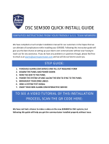
Figure 1: Wireless Gateway Module main components
Power LED
Bus LED
Auto LED
Unused LED
Status LEDs
Wiring terminals
Serial number label
Antenna jack
Wireless data transceiver
Table 1: Component functions
Component Function
Power LED Indicates module power status.
Bus LED Indicates panel bus communication.
Auto LED Indicates module/data transceiver
communications.
Status LED Indicate pager network communication status.
Wiring terminals Provide power, bus, and hardwire zone input
connections.
Before installation
Before installing any Wireless Gateway, you must:
1. Create the Alarm.com customer account prior to installing
the Wireless Gateway by logging into the Alarm.com
dealer website at the following location:
https://www.alarm.com/dealer
E-mail [email protected] to become a registered
Alarm.com dealer/installer.
2. Create the account at least 24 hours before installation to
ensure that the wireless module is activated properly on
the wireless network.
To create a new account:
1. Open a web browser and enter the Alarm.com dealer
website URL: https://www.alarm.com/dealer
2. Enter your dealer login and password and press GO.
3. Click the Check Coverage link at the top of the page to
check wireless coverage at the install location. If the
location has full coverage, proceed with the next steps. If
coverage is uncertain, you may contact Alarm.com for
more details.
4. Click the Customers link on the menu bar. Then click
Create Customer.
5. Enter the required customer information
P/N 466-19
94 • REV D • January 2011 1

Note: Ensure the customer e-mail address is entered
correctly. Alarm.com sends a confirmation message, and
a list of account changes, to the customer via e-mail.
6. Click Next. Step Two, Create Customer’s Login will
appear. Follow the directions as stated. You may click on
Automatically Generate Login to have a login assigned to
you.
7. Click Next. Step Three, System Location will appear. If the
system is installed at the address provided at Step One
Customer Information, click Yes. If the system is installed
at an address different from the one provided in Step One
Customer Information, click No and enter the correct
address and time zone where the system is to be installed.
It’s important that you enter the correct system location
address at this step.
8. Click Next. Step Four Panel Information will appear. In the
Modem Serial # dialog box, enter the 10-character ID
found on the gateway you purchased (see serial number
label in Figure 1 on page 1). If you are unable to proceed
w
ith the modem serial number, contact Alarm.com.
9. Select Concord in the Panel Type list box.
10. Click Next. The Confirmation screen will appear. Review
the customer information. If you need to change any of the
information, click the Edit link next to the field you want to
update.
11. Click Done. The Account Creation Successful screen will
appear. Click View and Print Welcome Letter. Print two
copies of the welcome letter; one for the customer and
one for your records. The letter includes the customer’s
login, temporary password, and instructions on how to get
started.
Also, a confirmation message is sent via e-mail to the
address entered in Step One: Customer Information. The
message contains a user confirmation number to be
entered during initial log on to the Alarm.com website.
Note: If you leave the Account Creation Successful screen
without printing a welcome letter, you must click on the
Customer Tab, choose the Customer Support tab, and
search for and click on the customer that needs a New
Welcome Letter. On the customer information page that
appears, select the New Welcome Letter tab in the
Customer Support Option panel on the left-hand side.
If the customer does not receive the confirmation e-mail,
you may send a new confirmation e-mail by selecting
Resend Confirmation Number in the Customer Support
Options panel.
Installation guidelines
• Concord (v2.6-later) panels support a maximum of one
wireless gateway or one automation module per system.
You cannot use both on a single panel.
• Concord 4 and Concord Express (v4) panels support one
wireless gateway and one automation module or two
automation modules per system.
• Use four-conductor, 22- or 18-gauge stranded wire to
connect the module to a panel.
• Do not exceed recommended maximum wire lengths from
a panel to a module (see Table 2 below).
Table 2: Wire lengths
Gauge Maximum Wire Length
22 ga. 40 feet
18 ga. 90 feet
• Mount the module as close to the panel as possible; the
module may be mounted inside a Concord 4 or Concord
Express (v4) enclosure. The module draws a maximum of
65 mA (continuous) and up to 1600 mA (instantaneous
peaks) from the panel or auxiliary power supply.
• When powering bus devices and hardwired sensors from
the panel, do not exceed the panel’s total power output.
Refer to specific panel documentation for further detail.
Tools and supplied
• Slotted and Phillips screwdrivers.
• Drill (3/8”-drive) and drill bits.
• Wire cutter/stripper.
• Four-conductor, 22-gauge or larger diameter stranded
wire.
• 2k Ohm EOL resistor (included).
• Modem antenna (included).
• #6 panhead screws and wall anchors (four each included).
Installation
Installation requires you to position and mount the module,
route and connect all wires, and install a cover tamper switch.
Avoid locating the module in areas with excessive metal or
electrical wiring, such as a furnace or utility room.
2 SuperBus 2000
Wireless Gateway Module Installation Instructions

Mounting the module
Caution: You must be free of static electricity while handling
electronic components. Touch a grounded metal surface
before touching a circuit board.
1. Remove panel AC power and disconnect the backup
battery.
2. Remove the module’s enclosure cover (see Figure 2
below).
3.
Fasten the antenna to the antenna jack (see Figure 1 on
pag
e 1).
4. Place the module backplate at the desired location; check
for levelness and mark the three mounting holes and the
wire access area (see Figure 2 below). Be sure to leave
12 to 18 in. above the backplate for the antenna.
Note: If you are mounting the module inside a Concord 4 or
Concord Express (v4) enclosure, remove the antenna knock-
out from the left expansion module and follow Steps 2 through
6 from the SuperBus 2000 8Z Input Module’s “Mounting the
Module in a Concord Cabinet” (466-1606 Rev. C).
Figure 2: Removing the enclosure/mounting hole locations
Press here and
remove from base
Mounting holes
Wire access
5. Drill for the mounting holes and install wall anchors. Next,
secure the module’s backplate to the wall with screws.
Wiring the module
1. Remove panel AC power and disconnect the backup
battery
2. Wire the module to panel bus and terminals (see Figure 3
below for Concord, Figure 4 below for Concord 4).
3.
If desired, connect an input device to the module Z1 and
ZCOM terminals (see Figure 3 below for Concord,
Figure 4 below for Concord 4).
Note: Figure 3 below and Figure 4 below illustrate basic
modu
le wiring connections for Concord (v2.6-later) panels. For
Concord 4 and Concord Express (v4) panels, the module must
be powered from the battery positive (+) terminal. Refer to
specific Concord 4 and Concord Express (v4) documentation
for further details.
Figure 3: Basic module wiring connections for Concord
+12V
+12V
A
A
B
B
GND
GND
Z1
ZCOM
BUS
3
4
5
6
<OR>
UL-Listed
normally
closed (N/C)
contacts
in series
UL-Listed
normally
open (N/O)
contacts
in parallel
2.0K ohm EOL resisto
r
(install at last contact)
Figure 4: Basic module wiring for Concord 4
+12V
+12V
A
A
B
B
GND
GND
Z1
ZCOM
BUS
3
4
5
6
UL-Listed
normally
open (N/O)
contacts
in parallel
2.0K ohm EOL resisto
r
(install at last contact)
UL-Listed
normally
closed (N/C)
contacts
in series
To + terminal
on battery
To panel’s battery
+ terminal
<OR>
Installing a cover tamper switch
We recommend that you install a cover tamper switch
(Figure 5 on page 4). Once programmed, if someone opens
the modu
le cover, the tamper switch opens and causes an
alarm.
1. On the module’s backplate, place the reed switch into the
reed switch holder.
2. Remove the magnet clip from the module cover. Next,
insert the magnet into the tabs on the module cover.
3. Press the magnet clip over the magnet until the clip locks
into place.
4. Connect the UL listed reed switch (with 2k Ohm EOL
resistor) to a module zone or unused hardwire input.
SuperBus 2000
Wireless Gateway Module Installation Instructions 3

Figure
5: Installing a cover tamper switch
To zone
Reed switch
Magnet clip
Magnet
Module cover
Module backplate
2.0K ohm
EOL resistor
input
Power up
This section describes how to power both the module and
panel.
1. Verify all wiring between the panel and module is correct.
2. If an auxiliary supply is used, reconnect the auxiliary
supply’s backup battery and AC power. Next, reconnect
the main backup battery and restore panel AC power.
Note: Each time a module is added or changed, you must
disconnect and reconnect panel AC power to ensure the panel
and module can successfully communicate.
Programming
1. In the Security menu, enter Installer Program mode and
set the Access Code Lock feature to OFF.
• The module’s Power LED lights. Next, the module’s Bus
and Auto LEDs light. The LEDs indicate successful
communication between the module and panel. The
yellow LED and bottom red LED light 5 to 8 minutes after
entering installer program mode. Also, the system
touchpad displays the correct date and time.
Caution: The panel’s Access Code Lock feature must be set
to OFF for the system to communicate with alarm.com
services.
The system’s date/time feature cannot set if you press a
system touchpad button during the 5 to 8 minute period.
Status LEDs
Status LEDs indicate the module’s current signal and status.
The bottom red LED indicates the module is registered and in
range. The yellow and green LEDs indicate the module’s
message status. The top LED is not used (see Table 3 below
for a complete
list of LED condition patterns).
If the Red LED remains:
• On – the module is registered and in range.
• Off – the module is out of range and not registered with
the network.
• Flashing – the module is registered but out of range.
If the Yellow LED remains:
• On – the first
message has been sent to and received by
Alarm.com services.
• Off – a message has not been sent by the module, or a
message failed.
• Flashing – the first message is being sent by the module.
If the Green LED remains:
• Off – The module is not currently sending a message.
• Flashing – a message is being sent by the module.
Table 3: LED status indicators
Number Red Yellow Green Condition
1 Off Off Off Just powered up; not
communicating with wireless
network.
2 On Off Off In range; first msg not sent;
not sending msgs
3 On Flashes Flashes In range; sending first msg;
currently sending msg
4 On On Off In range; first msg sent; not
sending msgs
5 On On Flashes In range; first msg sent;
currently sending msg
Troubleshooting/testing
Table 4: Troubleshooting
Problem Solution
Power LED remains off.
Turn off panel AC power and verify all
wiring is correct. All buffered
messages can be received from the
two-way paging network after restoring
power to the panel.
4 SuperBus 2000
Wireless Gateway Module Installation Instructions

Status LED fails to turn on
after
initial power up.
Ensure the Access Code Lock feature
is set to OFF.
Verify that a second module is not
learned into panel memory.
You may have to wait 5 to 8 minutes
for the module to communicate with
Alarm.com services
Touchpads/sirens continue
to sound when system is not
armed.
Press the touchpad’s Status button.
The panel reports the status issue and
stops beeping.
Customer new user setup
This section describes how to create a new subscriber account
on the Alarm.com Web site. It does not apply to wireless
backup customers. Be sure to discuss this section with your
customer prior to final installation.
After the system is installed and operating correctly, instruct
your customer to log on to the Alarm.com Web site. Your
customer will need the following items to complete the new
subscriber set-up procedure:
Note: Customers will not be able to complete the New User
Setup if the Alarm.com module was unable to send the list of
installed sensors.
• Login and temporary password included on the Alarm.com
Welcome Letter.
• Confirmation number sent from Alarm.com to your
customer’s e-mail address.
• Complete list of system sensors and wireless touchpads.
Note: This is needed to check the sensors list sent by the
Alarm.com module, and also to set the correct sensor
names at the website.
• A phone number and e-mail address for Alarm.com to
send notifications to.
After your customer has gathered the required information,
have your customer log on to https://www.alarm.com and login
by entering the correct login name and temporary password. A
New Subscriber Setup Wizard appears for the customer to
complete. Assist the customer, if necessary, in creating an
address book and turning on all Alarm.com notifications.
Customer information
Leave pages 6 and 7 from this document with your customer.
The information on these pages describes security system use
and limitations of the Alarm.com Web site. This information
does not appear in any Owner’s Manual or User Guide.
Specifications
Compatibility Concord (v2.6-later), Concord 4, and
Concord Express (v4) panels
Power requirements 12V nominal; 65 mA (continuous); 1600 mA
(instantaneous peak) maximum
Inputs One hardwire zone input
Paging network One wireless, two-way paging transceiver
(reflex 25 or reflex 50)
Power/Data Bus One four-wire, SuperBus 2000 auto-
addressing data bus
Indicators One module/panel Status LED; one module
Power LED; one Automation LED; three
wireless Status LEDs
Storage temperature -30 to 140°F (-34 to 60°C)
Operating temperature 32 to 120°F (0 to 49°C)
Humidity 90% relative, non-condensing
Case color Belgian Gray
Case material High-impact, ABS plastic
Dimensions 5.25 x 4.125 x 1.0 in. (L x W x H)
Installation Wall mount
Regulatory information
Manufacturer UTC Fire & Security Americas Corporation, Inc.
1275 Red Fox Rd., Arden Hills, MN 55112-6943,
USA
FCC compliance FCC Part 15 Information to the User
This device complies with Part 15 of the FCC
rules. Operation is subject to the following two
conditions:
This device may not cause harmful interference.
This device must accept any interference
received, including interference that may cause
undesired operation.
Changes or modifications not expressly approved
by Interlogix can void the user’s authority to
operate the equipment.
Contact information
For contact information, see www.utcfireandsecurity.com or
www.interlogix.com.
For technical support, toll-free: 888.437.3287 in the US
including Alaska, Hawaii, Puerto Rico, and Canada. Outside
the tool-free area, contact your dealer.
Copyright © 2011 Interlogix, a UTC Fire & Security Company.
All rights reserved.
SuperBus 2000
Wireless Gateway Module Installation Instructions 5

User information
System operation from Alarm.com web site
Operating your system through Alarm.com’s easy-to-use Web
interface gives you limited controls for managing your account,
viewing system status and history, and arming your system.
The limited controls for your Concord or Concord 4 system
from the Alarm.com Web site are provided in the sections
below. Web enabled features depend on selected service
packages and may vary.
Security control
Monitor sensor zones 1 to 96
Sensor zones 1 through 96 can be monitored for alarms and
optionally for trouble conditions. Sensor zones 1 through 59
may also be monitored for normal activity.
Control Partition 1 (non-UL Listed systems only)
W
hen disarming your system through the Alarm.com Web site,
if a fire alarm from a hardwired smoke detector sounds, you
must enter the disarm command twice. The first disarm
command cancels the alarm; the second disarm command
resets the smoke detector.
If intrusion sensors are open, you must enter the arming
command twice. This avoids a protest condition which may
delay system arming.
Change System Master and User Codes 1 to 100.
T
he Alarm.com Web site only tracks codes that have been
programmed and/or changed from the Web site. It is
recommended that you program System Master and User
Codes 1 to 100 through Alarm.com. An e-mail notification is
sent each time a user code is changed.
Sensor Text
Sensor text displayed on system touchpads is different from
sensor text displayed on the Alarm.com Web site. When
compared to the sensor text on your system touchpad, the
Alarm.com Web site only displays a limited amount of the
same text.
Sensor text on the Alarm.com Web site can be changed and/or
modified at anytime (40 character maximum) without effecting
the sensor text displayed on your touchpad.
• The Alarm.com Web site manages your installer
programmed sensor text as follows:
• Only the first three words of the sensor name are
displayed on the Web site.
• If the sensor text in your system was created using
individual letters (custom text programmed by your
dealer), only the first letter from each of the first three
words are displayed on the Web site.
• The following words are not supported by the Web site:
Aborted; Active; Activity; AM; Date; Disarmed; In; Install;
Latchkey; Load; No; Now; Please; PM; Program;
Progress; Schedule; To.
Security
The Security Tab includes System Summary and Sensor
Status sub tabs.
• System Summary – Displays arming state and status for
each sensor in your system.
• Sensor Status – Allows you to view status messages for
each sensor in your system (see Table 5 below for a
detai
led list of status messages)
Table 5: Status information
Status Event Sensors
OK No alarms, errors, or problems have
been reported. Doors/windows are
closed. Motion sensors have not
been activated in the last 10 minutes.
All Sensors
Open A door or window is open. Door/Windo
w Sensors
Activated A motion sensor has detected activity
within the last 10 minutes.
Motion
Sensors
Alarm! A sensor has been tripped and an
alarm set.
All Sensors
Bypassed A sensor/zone was OPEN when the
system was armed. As a result, the
sensor is not armed and will not
cause an alarm during the current
armed period.
All Sensors
(except fire
and carbon
monoxide)
Low Battery A sensor is reporting a low battery.
Open the sensor, check for battery
type, and replace.
All Sensors
Tampering /
Malfunction
Sensor has been tampered or lost
contact with the panel. If the status
persists, contact your dealer.
All Sensors
Automation
The Automation Tab (optional) controls the following functions:
• Lights – Turn individual lights on/off from any location.
• Light Schedules – Create schedules for individual lights
to turn on or off.
6 SuperBus 2000
Wireless Gateway Module Installation Instructions

SuperBus 2000 Wireless Gateway Module Installation Instructions 7
• Sensor-Light Interaction – Allow sensors to interact with
lights. For example, opening the front door automatically
turns on a hall light for five minutes.
Note: We recommend that you set Light Schedules and
Sensor-Light Interaction using only your system touchpad or
the Alarm.com Web site.
Notifications
The Notifications Tab allows you to control alarm notifications
and system activity or set notification options for events such
as battery failure or sensor tampering.
Note: Local alarms (which do not report to a central monitoring
station) are reported to Alarm.com.
• Alarm – Allows you to edit the sequence of phone
(optional) and e-mail notifications generated by an alarm.
You may also turn sensor notifications on or off. These
notifications are independent of, and separate from
Central Station Alarm Reporting.
• Normal Activity – Allows you to view and edit phone
(optional) and e-mail notifications generated during normal
activity and other nonalarm events, and choose the events
you would like to receive notification for. Nonalarm and
normal activity notifications are optional features.
People
The People Tab lets you add and modify members in your
Address Book.
• Address Book – Includes people to notify in cases of
alarm and normal activity.
• Edit Person – Edit the name and address for each person
in your Address Book.
• Add Person – Add a name and address to your Address
Book.
• User Codes – Manage User Codes and authority levels
for people in your Address Book.
History
The History Tab allows you to view a system reported event.
You can customize a History report based on date/time, device
or event type, or specific sensor. Activity recorded and
displayed in the History section is dependant on the Alarm.com
service plan that you have subscribed to.
You can download (save to your computer) any History report
by clicking on one of the following two icons: for Microsoft
Excel or for Microsoft Internet Explorer.
Clicking on the Microsoft Excel icon downloads a History report
in text format that can be opened in Windows Notepad or
Microsoft Excel. Once the report is saved on your computer,
right click on the file folder, select Open With, and select
Microsoft Excel as the program to open the file. If you click the
checkbox in the Always Use This Program to Open These
Files window, future files are automatically opened in Microsoft
Excel.
Clicking on the Microsoft Internet Explorer icon downloads a
History report in HTML format that can be opened in Microsoft
Internet Explorer. Once the report is saved to your computer,
click on the file and your Web browser automatically opens the
file.
Available Filters:
• Spe
cific Sensor or Device Type – Only events triggered
by a selected sensor or device type are displayed. You
must select a sensor or device type from the drop-down
menu; if not, the screen displays events for all devices.
• Event Type – Only specified event types are displayed. If
an event type is not selected from the drop-down menu,
the screen displays all event types.
• Date and Time Span – The Date field includes the current
date by default. By setting the date and choosing a time
span from the drop-down menu, you can view events that
occurred during a specified time period. Only those events
that occur between entered dates are displayed. The
History Tab displays, by default, current-day events only.
Columns:
• De
vice – Displays which device reported an event.
• Event – Displays an event type and who armed/disarmed
the panel.
• Time and Date – Displays the time and date of an event.
Note: The event date is displayed in dd-mmm-yy format. The
event time is displayed as local time.
Profile
The Profile Tab allows you to view and edit account
information, Web site password, and system information:
• Account Information – View and edit user information
such as address and e-mail.
• Change Password – Change your Web site password
(login code cannot be changed).
• System Information – View and edit system information
such as description, address of installed system, and
location type.
/