Page is loading ...

PARTS & SERVICE
MANUAL
Spray Star
Model 1000
PRIME MOVER
Spray Star 10-100-B
Starting Serial #100179 July, 1999
SMITHCO PRODUCT SUPPORT
1-800-891-9435
Hwy SS and Poplar Avenue, Cameron WI 54822
E-mail: [email protected]

Introduction Service Diagrams Parts Accessories Reference
CONTENTS
Introduction .......................................... 1-3
Safe Practices ..................................................................2
Specification .....................................................................3
Optional Equipment .........................................................3
Service .................................................. 4-9
Maintenance ................................................................. 4-6
Service Chart ....................................................................7
End User’s Service Chart.................................................8
Adjustments .....................................................................9
Storage .............................................................................9
Diagrams...........................................10-14
Wiring Diagram ........................................................ 10-11
Hydraulic Diagram ................................................... 12-13
Fitting Torque Charts......................................................13
Wiring Schematic ...........................................................14
Hydraulic Schematic ......................................................14
Parts ..................................................16-41
Body and Frame ....................................................... 16-19
Nose Cone ............................................................... 20-21
Front Axle .................................................................. 22-23
Fuel Tank .................................................................. 24-25
Hydraulic Tank .......................................................... 24-25
Foot Pedal Linkage .................................................. 26-29
Engine,Pumps, and Exhaust ................................... 30-31
Park Brake and Rear Axle......................................... 32-33
Poly Tank .................................................................. 34-35
Turbo-Quad Agitator ................................................. 34-35
34-103 Orbitrol ......................................................... 36-37
10-117 Hydraulic Pump............................................ 38-39
16-966 Hypro
®
Pump................................................ 40-41
Accessories .................................... 42-117
1010 Plumbing (Manual Valve) ................................ 42-45
1008 Plumbing (Raven 440) .................................... 46-49
1006 Plumbing (TeeJet 834).................................... 50-53
1004 Plumbing(Manual) .......................................... 54-57
1002 Plumbing (Raven 203) .................................... 58-61
1006 Controls (TeeJet 834) ..................................... 62-63
1008 Controls (Raven 440)...................................... 62-63
1002 Controls (Raven 203)...................................... 64-65
16-456 Flow Meter ................................................... 64-65
16-524/16-866 Motorized Control Valve ................... 66-67
16-968 Strainer ......................................................... 66-67
15-552 Manifold Ball Valve ....................................... 68-69
15-531 Control Valve ................................................ 70-71
10-268 3 Way Manual Valve ..................................... 72-73
10-160 Stainless Steel 15’ Manual Boom............... 74-77
10-301 15’ Terrain Following Boom ........................ 78-83
Nozzle Assembly ...................................................... 84-85
Wiring Diagram
(for 10-301 Terrain Fllowing Boom) ......84-85
RA Raindrop
®
Tips..........................................................86
XR TEEJET Tips .............................................................87
10-103 Electric Lift Kit............................................... 88-89
10-297 Hydraulic Lift Kit ........................................... 90-93
16-906 Electric Hose Reel ....................................... 94-95
16-129 Hose Reel.................................................... 96-97
10-107 Hose Reel Mounting Instructions................ 98-99
Hose Reel Plumbing............................................100-101
Electric Hose Reel Wiring .................................... 102-103
Hose Reel Adjustments .............................................. 102
10-105 Foam Marker ............................................ 104-107
15-504 Compressor ............................................ 108-109
15-505 Motor ......................................................... 110-111
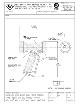
15-511 Foam Nozzle .............................................112-113
10-108 Speedometer Kit .......................................114-115
10-106 Fresh Water Wash Tank ...........................116-117
Reference...................................... 118-120
Decal List......................................................................119
Quick Reference Replacement Parts ......................... 120
Limited Warranty .................................. Inside Back Cover

1
Introduction
Information needed when ordering replacement parts:
1. Model Number of machine
2. Serial Number of machine
3. Name and Part Number of part
4. Quantity of parts
INTRODUCTION
Thank you for purchasing a product.
Read this manual and all other manuals pertaining to the Spray Star 1000 carefully as they have safety, operat-
ing, assembly and maintenance instructions. Failure to do so could result in personal injury or equipment dam-
age.
Keep manuals in a safe place after operator and maintenance personnel have read them. Right and left sides are
from the operator’s seat, facing forward.
All machines have a Serial Number and Model Number. Both numbers are needed when ordering
parts. The serial number plate on the Spray Star 1000 is located on the right main frame, in front of the oil tank.
Refer to engine manual for placement of engine serial number.
For easy access record your Serial and Model numbers here.

2
Introduction
SAFE PRACTICES
1. It is your responsibility to read this manual and all publications associated with this machine.
2. Never allow anyone to operate or service the machine or its optional equipment without proper training and
instructions. Never allow minors to operate any equipment.
3. Learn the proper use of the machine, the location and purpose of all the controls and gauges before you
operate the equipment. Working with unfamiliar equipment can lead to accidents.
4. Wear all the necessary protective clothing and personal safety devises to protect your head, eyes, ears,
hands and feet. Operate the machine only in daylight or in good artificial light.
5. Inspect the area where the equipment will be used. Pick up all debris you can find before operating.
Beware of overhead obstructions and underground obstacles. Stay alert for hidden hazards.
6. Never operate equipment that is not in perfect working order or without decals, guards, shields, or other
protective devices in place.
7. Never disconnect or bypass any switch.
8. Carbon monoxide in the exhaust fumes can be fatal when inhaled, never operate a machine without proper
ventilation.
9. Fuel is highly flammable, handle with care.
10. Keep engine clean. Allow the engine to cool before storing and always remove the ignition key.
11. Disengage all drives and set park brake before starting the engine.
12. Never use your hands to search for oil leaks. Hydraulic fluid under pressure can penetrate the skin and
cause serious injury.
13. This machine demands your attention. To prevent loss of control or tipping of the vehicle:
A. Use extra caution in backing up the vehicle. Ensure area is clear.
B. Do not stop or start suddenly on any slope.
C. Reduce speed on slopes and in sharp turns. Use caution when changing directions on slopes.
D. Stay alert for holes in the terrain and other hidden hazards.
14. Before leaving operator’s position:
A. Disengage all drives.
B. Set park brake.
C. Shut engine off and remove the ignition key.
D. If engine has to run to perform any maintenance keep hands, feet, clothing and all other parts of body
away from moving parts.
15. Keep hands, feet and clothing away from moving parts. Wait for all movement to stop before you clean,
adjust or service the machine.
16. Keep the area of operation clear of all bystanders.
17. Never carry passengers.
18. Stop engine before making repairs/adjustments or checking/adding oil to the crankcase.
19. Use parts and materials supplied by only. Do not modify any function or part.
20. Use caution when booms are down as they extend out beyond the center line of the machine.
21. The tank is a confined space, take precaution.
This machine is intended for turf maintenance. Other use is forbidden.

3
Introduction
SPECIFICATIONS
WEIGHTS AND DIMENSIONS
Length 112" (285 cm)
Width 70" (178 cm)
Width With Boom Open 180" (457 m)
Height 48" (122 cm)
Wheel Base 53" (135 cm)
Weight Empty 1283 lbs (582 kg)
Weight Full 2200 lbs (998 kg)
SOUND LEVEL (DBA)
At ear level 88 dba
At 3 ft (0.914 m) 84 dba
At 30 ft (9.14 m) 72 dba
ENGINE
Make Kohler
Model# Command CH25S
Type / Spec# PA 68620
Horsepower 25HP (18 kw)
Fuel Unleaded 87 Octane Gasoline Minimum
Cooling System Air Cooled
Lubrication System Full Pressure
Alternator 25 Amp
WHEELS & TIRE Front: Two 20 x 10.00 x 10 NHS Multi-Rib; 20psi (1.4 bar)
Rear: Two 24 x 12.00 x 12 NHS Multi-Trac; 20 psi (1.4 bar)
BRAKES Dynamic Through Hydrostat
PARK BRAKE Hand Operated Lever, Discs on Rear AxleSpeed 0 to 3 mph (0-4.8 kph)
SPEED
Forward Speed 0-8 mph (0-12.8 kph)
Reverse Speed 0-3 mph (0-4.8 kph)
BATTERY Automotive type 24F-12 Volt
BCI Group Size 24
Cold Cranking Amps 575 minimum
Ground Terminal Polarity Negative (-)
Maximum Length 10.25" (26 cm)
Maximum Width 6.88" (17 cm)
Maximum Height 10" (25 cm)
FLUID CAPACITY
Crankcase Oil See Engine Manual
Fuel 5 gallon (19 liters)
Hydraulic Fluid 5 gallon (19 liters)
Grade of Hydraulic Fluid SAE 10W-40 API Service SJ or higher Motor Oil
OPTIONAL EQUIPMENT
10-108 Speedometer Kit 10-260 203 Spray System (1002)
10-106 Fresh Water Tank 10-102 Manual Spray System (1004)
10-103 Electric Actuator Lift Kit 10-101 834 Spray System (1006)
10-297 Hydraulic Actuator Lift Kit 10-110 440 Spray System (1008)
10-105 Foam Marker 10-270 3-Way Manual System (1010)
10-160 15' Stainless Steel Boom - manual 15-577 18' Stainless Steel Boom - manual
10-301 15' Terrain Following Boom 10-300 18' Terrain Following Boom
10-107 Hose Reel Mounting Kit 33-216 Battery Automotive Type 24F-12 volt
16-129 Hose Reel 200'(61 m) capacity (to be used with 10-107)
16-906 Hose Reel 12 volt electric rewind 200' (61 m) capacity (to be used with 10-107)

4
Service
MAINTENANCE
Before servicing or making adjustments to machine, stop engine and remove key from
ignition.
Use all procedures and parts prescribed by the manufacturer's. Read the engine manual
before operation.
LUBRICATION
Use No. 2 General purpose lithium base grease and lubricate every 100 hours. The Spray Star 1000 has 9
grease fittings.
A. One on the rod end of hydraulic cylinder.
B. One on each the right and left spindles.
C. One on the center front pivot.
D. One on the pump pivot.
E. One on the brake relay.
F. One on the pedal relay.
G. One on the reverse pedal.
H. One on the forward pedal.
Every 500 hours of operation, seperate the hydrostatic pump and the engine, clean the splined areas and lightly
grease the male portion of the pump spline. Use either Dow Corning® G-N Metal Assembly Paste or #77 As-
sembly Paste (Kohler# 25 357 12-s).
As you mount the pump back onto the engine, be certain the mating surfaces are clean and free of any foreign
material and that the pump is correctly aligned.
EELCTRICAL CONNECTIONS
Use dielectric grease on all electrical connections.

5
Service
MAINTENANCE
AIR CLEANER
1. Loosen cover retaining knob and remove cover.
2. Remove pre-cleaner from paper element.
3. Check paper element. Replace element as necessary.
4. Wash pre-cleaner in warm water with detergent. Rinse pre-cleaner thoroughly until all traces of detergent
are eliminated. Squeeze out excess water (do not wring). Allow pre-cleaner to air dry.
5. Saturate pre-cleaner with new engine oil. Squeeze out all excess oil.
6. Reinstall pre-cleaner over paper element.
7. Reinstall air cleaner cover. Secure cover with cover retaining knob.
ENGINE OIL
Change and add oil according to chart below based on air temperature at the time of operation. Do not overfill.
Use a high quality detergent oil classified "For Service SJ or higher" oil. Use no special additives with recom-
mended oils. Do not mix oil with gasoline.
SAE Viscosity Grades
Starting Temperature Range Anticipated Before Next Oil Change
HYDRAULIC OIL
1. Use SAE 10W-40 API Service SJ or higher motor oil.
2. For proper warranty, change oil every 500 hours or annually, which ever is first.
3. Oil level should be 2-2½" (5-6.4cm) from top of the tank when fluid is cold. Do not overfill.
4. After changing oil, run the machine for a few minutes. Check oil level and for leaks.
5.
Always use extreme caution when filling hydraulic oil tank or checking level to keep system free of
contaminants. Check and service more frequently when operating in extremely cold, hot or dusty condi-
tions.
6. If the natural color of the fluid has become black or smells burnt, it is possible that an overheating problem
exists.
7. If fluid becomes milky, water contamination may be a problem.
8. If either of the above conditions happen, change oil immediately after fluid is cool and find the cause. Take
fluid level readings when the system is cold.
9. In extreme temperatures you can use straight weight oil. We recommend SAE 30W API Service SG when
hot (above 90°F (33°C)) and SAE 10W API Service SJ or higher when cold (below 32°F (0°C) ambient
temperature. Use either motor oil or hydraulic oil, but do not mix.
10. Oil being added to the system must be the same as what is already in the tank. Mark the tank fill area as
to which type you put in.
DIRECTO VALVES
Directo Valves should be disassembled, cleaned, inspected, and a service kit installed annually. More often
depending on the chemicals being used and the frequency of use. In most cases this can be done without re-
moving the valve from the sprayer.

6
Service
MAINTENANCE
TIRE PRESSURE
Caution must be used when inflating a low tire to recommended pressure. Over inflating can cause tires to ex-
plode. All tires should be 20 psi (1.4bar). Improper inflation will reduce tire life considerably.
WHEEL MOUNTING PROCEDURE
1. Set park brake. Turn machine off and remove key.
2. Block wheel on opposite corner.
3. Loosen nuts slightly on wheel to be removed.
4. Jack up machine being careful not to damage underside of machine.
5. Place wheel on hub lining up bolt holes.
6. Torque to 64-74 ft/lb (87-100Nm) using a cross pattern. Retorque after first 10 hours and every 200 hours
thereafter.
7. Lower machine to ground and remove blocks and jack.
BATTERY
Batteries normally produce explosive gases which can cause personal injury. Do not allow flames, sparks or any
ignited object to come near the battery. When charging or working near battery, always shield your eyes and
always provide proper ventilation.
Battery cable should be disconnected before using “Fast Charge”.
Charge battery at 15 amps for 10 minutes or 7 amps for 30 minutes. Do not exceed the recommended charging
rate. If electrolyte starts boiling over, decrease charging.
Always remove grounded (-) battery clamp first and replace it last. Avoid hazards by:
1. Filling batteries in well-ventilated areas.
2. Wear eye protection and rubber gloves.
3. Avoid breathing fumes when electrolyte is added.
4. Avoid spilling or dripping electrolyte.
Battery Electrolyte is an acidic solution and should be handled with care. If electrolyte is
splashed on any part of your body, flush all contact areas immediately with liberal amounts
of water. Get medical attention immediately.
Use of booster battery and jumper
cables. Particular care should be
used when connecting a booster
battery. Use proper polarity in order
to prevent sparks.
TO JUMP START (NEGATIVE GROUNDED BATTERY):
1. Shield eyes.
2. Connect ends of one cable to positive (+)
terminals of each battery, first (A) then (B).
3. Connect one end of other cable to negative (-)
terminal of "good" battery (C).
4. Connect other end of cable (D) to engine block on unit being started (NOT to negative (-) terminal of
battery)
To prevent damage to other electrical components on unit being started, make certain that engine is at idle
speed before disconnecting jumper cables.

7
Service
SERVICE CHART KOHLER COMMAND 25HP
Before servicing or making adjustments to the machine, stop engine, set park break, block
wheels and remove key from ignition.
Follow all procedures and ONLY use parts prescribed by the manufacturer. Read the engine
manual before maintenance.
C=Check or Clean at specified intervals
R=Replace at specified intervals
* Tire pressure: 20 psi (1.4 bar) Front and Rear.
† Replace hydraulic filter after the first 20, 100, and every 250 there after.
§ Torque tire nuts after the first 10 hours and every 200 hours there after (64 to 74 ft/lb (87-100Nm))
¤ Change Oil and Filter after first 5 hours.
‡ Clean more often under dusty conditions or when airborne debris is present , replace air cleaner parts, if very dirty.
The suggested maintenance checklist is not offered as a replacement for the manufacturer’s engine manual but
as a supplement. You must adhere to the guidelines established by the manufacturer for warranty coverage. In
adverse conditions such as dirt, mud or extreme temperatures, maintenance should be more frequent.
Daily
As Required
100 Hours
200 Hours
250 Hours
300 Hours
400 Hours
Every 500 Hours/Yearly
¤ Engine Oil w/ Filter 2.1qt. (2 l) C R R R R R
¤ Engine Oil Filter R R R
Engine for Leaks and Loose Parts C C C C C C
‡ Air Cleaner (Paper Element) C C C C C R
‡ Pre-Cleaner (Every 25 hours) C C C C C C R
Spark Plugs R C C R
Idle Speed (1200 RPM) C C
‡ Cooling System C C C C C C
Belts and Hoses C C C
* Tire Pressure C C C C C C
Visual Inspection of Tires C C C C C C
Fuel Level C C
Fuel Filter R R
Hydraulic Oil C C C C C R
†Hydraulic Oil Filter R R
Hydraulic System for Leaks and Loose Parts C C C C C C
Battery Electrolyte Level C C C C C
Clean Battery Terminals C C
§ Torque Lug Nuts C C C
Lubricate C C C C C
Lubricate Splines on Hydrostatic Pump Every 500 hours

8
Service
END USER'S SERVICE CHART
C=Check or Clean at specified intervals
R=Replace at specified intervals
* Tire pressure: 20 psi (1.4 bar) Rear. 22 psi (1.5 bar) Front.
† Replace hydraulic filter after the first 20, 100, and every 250 there after.
§ Torque tire nuts after the first 10 hours and every 200 hours there after (64 to 74 ft/lb (87-100Nm))
¤ Change Oil and Filter after first 5 hours.
‡ Clean more often under dusty conditions or when airborne debris is present , replace air cleaner parts, if very dirty.
Daily
As Required
100 Hours
200 Hours
250 Hours
300 Hours
400 Hours
Every 500 Hours/Yearly
¤ Engine Oil w/ Filter 2.1qt. (2 l)
¤ Engine Oil Filter
Engine for Leaks and Loose Parts
‡ Air Cleaner (Paper Element)
‡ Pre-Cleaner (Every 25 hours)
Spark Plugs
Idle Speed (1200 RPM)
‡ Cooling System
Belts and Hoses
* Tire Pressure
Visual Inspection of Tires
Fuel Level
Fuel Filter
Hydraulic Oil
†Hydraulic Oil Filter
Hydraulic System for Leaks and Loose Parts
Battery Electrolyte Level
Clean Battery Terminals
§ Torque Lug Nuts
Lubricate
Lubricate Splines on Hydrostatic Pump

9
Service
ADJUSTMENTS
WHEEL CREEP
"Creep" is when the engine is running and hydrostatic transmission is in neutral, but due to inadequate align-
ment, wheels still move. Do the following procedure to stop this motion.
1. Lift up and support machine so rear wheels are off the ground and can turn freely.
2. In the engine compartment, the hydrostatic transmission is on the left
side. The swash plate(D) is under the transmission and comes out
forward. The idler arm(B) has a bearing that runs in the notch of the
swash plate. Loosen bolt (A).
3. With engine running, move bearing(B) so it centers on the swash
plate(D) and 'wheel creep' stops.
4. Tighten all fasteners and test by using foot pedal linkage to see that
'creep' is removed.
5. Turn engine off and lower machine.
SPRAY PUMP WITH ELECTRIC CLUTCH BELT
Located to the rear and right of the engine. Should have approximately
1
/2" (13mm) of deflection in the center of
the top strand. Loosen and tighten the
5
/16 -18 x 1
1
/4 set screw located on the foot of the pump mount.
PARK BRAKE
Turn knob clockwise on end of park brake to tighten. Turn it counter clockwise to loosen. If finer adjustment is
needed turn clevis on brake cable to adjust length of cable.
SPEED CALIBRATION NUMBERS
The speed calibration numbers for the Spray Star 1006 is 120.
The speed calibration numbers for Spray Star 1008 is 612.
STORAGE
If the engine will be out of service for two or more months, use the following storage procedure.
1. Clean the exterior surfaces of the engine.
2. Change the oil and filter while the engine is still warm from operation.
3. The fuel system must be completely emptied, or the gasoline must be treated with a stabilizer to prevent
deterioration.
If you choose to use a stabilizer, follow manufacturers recommendations, and add the correct amount for
the capacity of fuel system. Fill fuel tank with clean, fresh gasoline. Run engine for 2-3 minutes to get
stabilized fuel into carburetor. Close fuel shut-off valve when unit is being stored or transported.
To empty the system, drain fuel tank and carburetor, or run engine until tank and system are empty.
4. Remove the spark plugs. Add one tablespoon of engine oil into each spark plug hole. Install plugs, but do
not connect the plug leads. Crank the engine two or three revolutions.
5. Store machine in a clean, dry place.

10
Diagrams
Color Code Chart
Bl Blue
Br Brown
Y Yellow
Grn Green
O Orange
R Red
B Black
P Purple
W White
WIRING DIAGRAM
Use dielectric grease on all electrical connections.
FUSES
Boom Lift 20 AMP 33-272
Manifold Valve 5 AMP 33-284
Spray Systems 15 AMP 33-508
Foamer 10 AMP 33-507
Hose Reel 30 AMP 33-273

11
Diagrams
WIRING PARTS LIST
REF# PART# DESCRIPTION QUANTITY
1† 10-202 Speedometer 1
8859 Ring Terminal
3
/16 2
8962 Heat Shrink 2
2 8935 Buss Bar (-) 1
3 13-288 Ignition Switch (Kohler 25 099 04) 1
76-310 Key Set 1
4 34-146 Panel Mounted Circuit Breaker 1
34-145 Circuit Breaker Boot 1
5 8935 Buss Bar(+) 1
6§ Speedometer To (+) Buss Bar
7§ (-) Buss Bar to Hour / Voltmeter
8 42-064 Hour / Voltmeter Combo 1
9 10-182 Hot Wire Hour / Voltmeter 1
10 50-359 Oil Warning Light 1
8849-2 Black Wire 1
8860 String Connector 1
8859 Ring Terminal
3
/16 1
8853 Slide On Connector 1
8962 Heat Shrink
3
/16 3
11 Oil Sender (Part Of Engine)
12 Ignition Module (Part Of Engine)
13 Fuel Shut-Off Solenoid (Part Of Engine)
14 Rectifier (Part Of Engine)
15 Starter (Part Of Engine)
16 10-167 Red Battery Cable 1
17 22-073 Battery (Optional) 1
18 76-327 Ground Battery Cable 1
19 10-204 Fuse Block Ground Wire 1
20 33-271 Fuse Block 1
21 10-203 Fuse Block Hot Wire 1
22 Wire With Fuse (Part Of Engine)
Fuse AGC 30
23§ (-) Buss Bar to Ignition Switch
24 77-207 Buzzer 1
8845-3.5 White Wire 1
8860 String Connector 1
8859 Ring Terminal
3
/16 1
8853 Slide On Connector 1
8962 Heat Shrink 3
25§ Wire Toggle Switch To (+) Buss Bar
26 33-480 Pressure Switch 1
27 15-314 Toggle Switch 1
15-472 Switch Boot 1
28 16-966 Hypro Pump With Electric Clutch 1
29† 10-183 Wire Speedometer Ground 1
30† 16-883 Magnetic Sensor 1
31† 10-209 Speedometer Wire Harness 1
32 14-272 Seat Switch 1
10-262 Wire Harness (Includes all wire colors with *) 1
§ 10-224 Console Wire Harness 1
† 10-108 Speedometer Kit (optional)

12
Diagrams
HYDRAULIC DIAGRAM

13
Diagrams
HYDRAULIC DIAGRAM PARTS LIST
REF# PART# DESCRIPTION QUANTITY
1 10-143 Hydraulic Hose 2
2 10-135 Hydraulic Cylinder 1
3 10-141 Hydraulic Hose 1
4 34-103 Orbitrol Motor 1
5 10-144 Hydraulic Hose 1
6 10-142 Hydraulic Hose 1
7 18-190 Tee 1
8 34-105 Oil Cooler 1
9 10-145 Hydraulic Hose 1
10 10-116 Wheel Motor 2
11 10-123 Hydraulic Hose 4
12 8832-12 Hose
3
/4 ID 1
18-222 Hose Clamp 2
13 23-006 Oil Filter 1
23-031 Replacement Filter
14 8832-14 Hose
3
/4 ID 1
18-222 Hose Clamp 2
15 10-196 Hydraulic Hose 1
16 48-135 Oil Tank 1
17 10-140 Hydraulic Hose 2
18 10-117 Hydrostatic Pump 1
FITTING TORQUE CHARTS
Over tightened fittings will result in crushing the cone which will create a leak.
Charts Developed by Parker Henniphin
in. lbs. ft. lbs. in. lbs. ft. lbs.
2 5/16 - 24 35 ± 5 3 ± .5 90 ± 5 7.5 ± .5
3 3/8 - 24 60 ± 5 5 ± .5 170 ± 10 14 ± 1
4 7/16 - 20 135 ± 10 11 ± 1 220 ± 15 18 ± 1
5 1/2 - 20 180 ± 10 15 ± 1 260 ± 15 22 ± 1
6 9/16 - 18 220 ± 10 18 ± 1 320 ± 20 27 ± 2
8 3/4 - 16 550 ± 20 46 ± 2 570 ± 25 48 ± 2
10 7/8 - 14 900 ± 50 75 ± 5 1060 ± 50 90 ± 5
12 1 1/16 - 12 1020 ± 50 85 ± 5 1300 ± 50 110 ± 5
14 1 3/16 - 12 1550 ± 75 130 ± 6 1750 ± 75 145 ± 6
16 1 5/16 - 12 1600 ± 75 135 ± 6 1920 ± 75 160 ± 6
20 1 5/8 - 12 2700 ± 150 225 ± 12 2700 ± 150 225 ± 12
24 1 7/8 - 12 3000 ± 150 250 ± 12 3000 ± 150 250 ± 12
32 2 1/2 - 12 3900 ± 200 325 ± 15 3900 ± 200 325 ± 15
SAE Straight Thread O-ring Plugs
(Steel)
Fitting
Size
SAE Port
Thread
Hollow Hex Head Plug
(HP5ON) Assembly
Torque
Hex Head Plug (P5ON)
Assembly Torque
in. lbs. ft. lbs.
4 7/16 - 20 190 ± 10(1) 16 ± 1.0
6 9/16 - 18 420 ± 15 35 ± 1.0
8 3/4 - 16 720 ± 25 60 ± 2.0
10 7/8 - 14 1260 ± 50 105 ± 5.0
12 1 1/16 - 12 1680 ± 75 140 ± 6.0
16 1 5/16 - 12 2520 ± 100 210 ± 8.0
20 1 5/8 - 12 3100 ± 150 260 ± 12.0
24 1 7/8 - 12 3800 ± 150 315 ± 12.0
Seal-Lok Strai
g
ht and Adjustable Fittin
g
(Steel)
Assembly Torque (2)
Fitting
Size
SAE Port
Thread
Size

14
Diagrams
WIRING SCHEMATIC
HYDRAULIC SCHEMATIC

15
NOTES

16
Parts
BODY & FRAME DRAWING

Parts
17
BODY & FRAME PARTS LIST
REF# PART# DESCRIPTION QUANTITY
1 10-111 110 Gallon Poly Tank 1
2 10-193 Horizontal Boom Support 1
3 10-191 Tank Strap 2
4 14-269 Seat 1
14-272 Seat Switch 1
42-098 Plastic Spacer 4
HB-516-18-125 Bolt
5
/16 - 18 x 1
1
/4 4
HW-516 Washer
5
/16 4
HWL-516 Lock Washer
5
/16 4
HN-516-18 Nut
5
/16 - 18 4
5 10-120 Park Brake Handle 1
6 48-135 Oil Tank 1
23-095 Filler Breather 1
7 10-257 Left Side Panel 1
HSDPS-14-075 Stainless Pan Head Drill Screw
1
/4 x
3
/4 9
8 15-030 Steering Wheel 1
9 10-180 Left Front Fender 1
HBC-516-18-100 Carriage Bolt
5
/16 - 18 x 1 4
HW-516 Washer
5
/16 4
HWL-516 Lock Washer
5
/16 4
HN-516-18 Nut
5
/16 - 18 4
10 76-299 Black Boot 1
11 10-113 Console 1
12 10-239 Seat Panel 1
13 10-163 Forward Foot Pedal 1
14 10-164 Reverse Foot Pedal 1
15 10-137 Main Frame 1
16 11-086 Choke 1
17* 10-238 Two Bank Valve 900 PSI 1
10-248 Valve Handles 2
18 10-118 Kohler 25 hp Engine 1
19 16-857 Tire and Wheel 2
16-857-01 Tire 20 x 10 - 10NHS 4 Ply 2
16-857-02 Wheel 2
20 10-159 Right Front Fender 1
HBC-516-18-100 Carriage Bolt
5
/16 - 18 x 1 4
HW-516 Washer
5
/16 4
HWL-516 Lock Washer
5
/16 4
HN-516-18 Nut
5
/16 - 18 4
21 10-258 Right Side Panel 1
HSDPS-14-075 Stainless Pan Head Drill Screw
1
/4 x
3
/4 9
22 34-105 Oil Cooler 1
HB-14-20-100 Bolt
1
/4 - 20 x 1 4
HWL-14 Lock Washer
1
/4 4
HN-14-20 Nut
1
/4 - 20 4
10-129 Front Cooler Mount 1
10-130 Rear Cooler Mount 1
* 10-297 Hydraulic Lift Kit 1
(Continued on Next Page)

18
Parts
BODY & FRAME DRAWING
/