Page is loading ...

1
FrameSaver
®
DSL Router
Models 9783 and 9788
Quick Reference
Document Number 9700-A2-GL11-00
July 2002
Product Documentation Online
Complete documentation for this product is available at
www.paradyne.com
. Select
Library
→
Technical Manuals
→
FrameSaver Frame Relay Devices.
Select the following documents:
9000-A2-GB20
Configuring Frame Relay Service Over DSL
9700-A2-GB20
FrameSaver DSL
,
Models 9783 and 9788,
User’s Guide
To order a paper copy of a Paradyne document:
Within the U.S.A., call 1-800-PARADYNE (1-800-727-2396)
Outside the U.S.A., call 1-727-530-8623
Getting Started
If you have not yet installed and set up the FrameSaver
®
DSL router, do so now. Refer to
the
FrameSaver DSL Router, Models 9783 and 9788, Installation Instructions,
Document Number 9700-A2-GN11, that came with the router.
Before starting to use the FrameSaver DSL router, it is recommended that you download
the User’s Guide so you have access to information about the device, then print
chapters or sections you may want to reference.
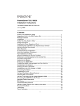
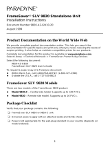
Menu Hierarchy
The Menu Hierarchy shows a pictorial view of the organization of the FrameSaver
router’s screens, which can help you navigate the menus and access information.

2
02-16974a-01
Menu Hierarchy
Status
System and Test Status
IP Path Connection Status
PVC Connection Status
Network Interface Status
IP Routing Table
(Management Traffic)
Performance Statistics
Trap Event Log
Display LEDs
and Control Leads
Identity
Identity
• System
• NAM
Network
Interface
Status
• Operating
Rate
• Receiver
Attenuation
• SNR Margin
PVC
Connection
Status
• Source Link,
DLCI, EDLCI
• Primary
Destination
Link, DLCI,
EDLCI Status
Performance
Statistics
• Service Level
Verification (SLV)
• DLCI
• Frame Relay
• ATM
• VCC
• xDSL Line (9788)
• Ethernet
• Clear All Statistics
System and
Test Status
• Self-Test
Results
• Last Reset
• Health and
Status
• Test Status
Test
Network PVC Tests
Network ATM
Loopback Tests
Network Physical
Tests (9788)
IP Ping
Lamp Test
Abort All Tests
Network
PVC Tests
(DLCI Number)
• PVC Loopback
• Send Pattern
• Monitor Pattern
• Connectivity
IP Routing
Table for
Management
Traffic
• Destination
• Mask
• Gateway
• Hop
• Type
• Interface
• TTL
Trap Event
Log
• Number of
Trap Events
• Time Elapsed
Since Event
• Event
Configuration
Edit/Display
System
Network
Virtual Router Ports
PVC Connections
IP Path List
Management and
Communication
Network
• Physical
• Frame Relay
• Circuit
Records
• ATM
System
• Class of
Service
Definitions
• Service Level
Verification
• General
PVC Connection
Table
• Source Link, DLCI,
EDLCI
• Primary Destination
Link, DLCI, EDLCI
Management and
Communication
• Node IP
• Management PVCs
• General SNMP Management
• Telnet and FTP Sessions
• SNMP NMS Security
• SNMP Traps
• Ethernet Management
• Communication Port
• External Modem (Com Port)
New or Modify
PVC Connection Entry
Load
Configuration
From:
Command
Line
Interface
Virtual Router
Ports
• DLCI Records
MAIN MENU
Status
Test
Configuration
Control
Easy Install
MAIN MENU
Status
Test
Configuration
Control
Easy Install
MAIN MENU
Status
Test
Configuration
Control
Easy Install
Shift-r
Network ATM
Loopback Tests
(VPI, VCI)
• ATM Ping
Network
Physical Tests
• Transparent
Pass-through
• 511 Pattern Test
IP Path
Connection
Status
• Device Name
• IP Address
• Status
• Discovery
Source
IP Path List
• Add and
Display Static
Paths
New or Modify
Management
PVC Entry

3
Configuration Roles
The FrameSaver DSL Router has several interfaces that may be provisioned by different
parties:
Frame relay, ATM, and physical layer provisioning – Typically set up by the
CLEC (Competitive Local Exchange Carrier) or the frame relay NSP (Network
Service Provider), using the menu-driven interface accessed via an ASCII terminal
connection or Telnet session.
Router provisioning with Command Line Interface (CLI) – Typically accessed by
the end user or a frame relay NSP that provides managed router service.
SLM provisioning – Typically set up by the CLEC or frame relay NSP.
01-16974b
System Information
• Device Name
• System Name,
Location, Contact
• ATM Location ID
• Date
• Time
Control
System Information
Administer Logins
Change Operating Mode
Select Software Release
Reset Device
Administer Logins
• Login ID
• Password
• Access Level
New
Login Entry
Select Software Release
• Current Release
• Alternate Release
Easy Install
• DSLAM Type (9783)
• Node IP Address
• Node Subnet Mask
• TS Access
• Create Dedicated Network Management Link
• Ethernet Management Options Screen
• Network 1 DSL Line Rate (Kbps)
• Network 1 FRF.8 Encapsulation Mode
MAIN MENU
Status
Test
Configuration
Control
Easy Install
MAIN MENU
Status
Test
Configuration
Control
Easy Install

4
Configuration Option Summaries
The following sections summarize the configuration options accessed when you select
Configuration from the Main Menu.
System Configuration Options
From the Configuration menu, select System to configure options applicable to the entire
system.
Class of Service Definitions
Service Level Verification
General
Class of Service Definitions
Select Class of Service Definitions to configure class of service and code point
definitions.
Class of Service Definitions
Configuration Option Settings
Default in
[Bold]
Class of Svc Name
ASCII text
(8 characters)
Measure Latency & Availability N, Y
Code Points Assigned N, Y
Code Point Definitions
Code Pnt 000000–111111
ID 1–7
Name
ASCII text
(8 characters)

5
Service Level Verification
Select Service Level Verification to configure SLV options for the router.
General
Select General to configure a timeout period and duration for user-initiated loopbacks
and pattern tests.
Service Level Verification
Configuration Option Settings
Default in [
Bold
]
SLV Sample Interval (secs.) 10–3600 [
60
]
SLV Synchronization Role [
Tributary
], Controller, None
SLV Type Standard, COS 1–COS 7
SLV Delivery Ratio Enable,
[
Disable
]
DLCI Down on SLV Timeout Enable,
[
Disable
]
SLV Timeout Error Event
Threshold
1–20 [
3
]
SLV Timeout Clearing Event
Threshold
[
1
]–20
SLV Round Trip Latency Error
Threshold (ms)
50–[
10000
]
SLV Latency Clearing Event
Threshold
1–20 [
2
]
SLV Packet Size (bytes) [
64
]–2048
General
Configuration Option Settings
Default in [
Bold
]
Test Timeout [
Enable
],
Disable
Test Duration (min.) 1–120 [
10
]

6
Network Configuration Options
From the Configuration menu, select Network to configure options applicable to the
network interface.
Physical
Frame Relay
Circuit Records
AT M
Physical
Select Physical to configure physical characteristics for the DSL network interface.
Physical (9783)
Configuration Option Settings
Default in [
Bold
]
Line Rate Mode Hunt, [
AutoRate
], Fixed
DSL Line Rate (Kbps)
The default and available line rates depend on
the setting of DSLAM Type. See Easy Install in
the Installation Instructions.
144, 192, 208, 256, 272, 384, 400, 512, 528,
768, 784, 1024, 1152, 1168, 1536, 1552, 2320
SNR Margin Alarm Threshold (dB) –5, –4, –3, –2, –1, 0, 1, 2, [
3
], 4, 5, 6, 7, 8,
9, 10

7
Frame Relay
Select Frame Relay to specify whether Traffic Policing will be used on the DSL network
interface.
Physical (9788)
Configuration Option Settings
Default in [
Bold
]
Line Rate Mode [
AutoRate
], Fixed
DSL Line Rate (Kbps)
If PSD Mask is Symmetric:
200, 264, 328, 392,
456, 520, 584, 648, 712, 776, 784, 840, 904, 968,
1032, 1096, 1160, 1224, 1288, 1352, 1416, 1480,
1544, 1552, 1608, 1672, 1736, 1800, 1864, 1928,
1992, 2056, 2120, 2184, 2248, 2312
If PSD Mask is Asymmetric and Region Setting is
Annex A:
776, 784, 1544, 1552
If PSD Mask is Asymmetric and Region Setting is
Annex B:
2056, 2312
Region Setting Annex A, Annex B
PSD Mask Asymmetric, [
Symmetric
]
Frame Relay
Configuration Option Settings
Default in [
Bold
]
Traffic Policing [
Enable
], Disable

8
Circuit Records
Select Circuit Records to manually configure Circuit Records for each interface.
Circuit Records
Configuration Option Settings
Default in [
Bold
]
DLCI Number 16–1007 [
blank
]
DLCI Type Standard, [
Multiplexed
], IP Enabled
VPI 0–15 [
blank
]
VCI 32–255 [
blank
]
CIR (bps) [
0
]–2320000 (9783)
[
0
]–2312000 (9788)
T
c
This field displays the committed rate
measurement interval to be used for the DLCI
based upon the displayed option settings.
Committed Burst Size B
c
(Bits) [
CIR
], Other
B
c
[
0
]–2320000 (9783)
[
0
]–2312000 (9788)
Excess Burst Size B
e
(Bits) 0–[
2320000
] (9783)
0–[
2312000
] (9788)
Outbound Management Priority Low, [
Medium
], High

9
ATM
Select ATM to configure the ATM characteristics for the DSL network interface.
Virtual Router Port Configuration Options
From the Configuration menu, select Virtual Router Ports, then DLCI Records to
configure DLCI Records on the virtual router port (S0 – Serial Port 0).
ATM
Configuration Option Settings
Default in [
Bold
]
Cell Payload Scrambling [
Enable
], Disable
Cell Delineation Error Event
Threshold
1–1000 [
10
]
FRF.8 Encapsulation Mode [
Transparent
], Translation
DLCI Records
Configuration Option Settings
Default in [
Bold
]
DLCI Number 16–1007
CIR (bps) [
0
]–2320000 (9783)
[
0
]–2312000 (9788)
T
c
This field displays the committed rate
measurement interval to be used for the DLCI
based upon the displayed option settings.
Committed Burst Size B
c
(Bits) [
CIR
], Other
B
c
[
0
]–2320000 (9783)
[
0
]–2312000 (9788)
Excess Burst Size B
e
(Bits) 0–[
2320000
] (9783)
0–[
2312000
] (9788)
DLCI Priority Low, Medium, [
High
]

10
IP Path List
Select IP Path List (Static) to configure the list of static path IP addresses.
PVC Connections Configuration Options
From the Configuration menu, select PVC Connections to manually configure logical
connections.
The C
reatePVC function key on the Network Circuit Records screen provides easy
configuration of PVC connections. For management PVC configuration options, see
Management PVCs
on page 12.
IP Path List
Configuration Option Settings
Default in
[Bold]
IP Address 000.000.000.001–223.255.255.255
FWD [
No
], Yes
PVC Connections
Configuration Option Settings
Default in [
Bold
]
Source Link Rtr-S0, Net1-FR1 [
blank
]
Source DLCI 16–1007 [
blank
]
Source EDLCI 0–62 [
blank
]
Destination Link Net1-FR1 [
blank
]
Destination DLCI 16–1007 [
blank
]
Destination EDLCI 0–62
[blank
]

11
Management and Communication Configuration Options
From the Configuration menu, select Management and Communication to configure the
FrameSaver router so it can be managed by an NMS or via a Telnet session and to
select appropriate protocols.
Node IP
Management PVCs
General SNMP Management
Telnet and FTP Sessions
SNMP NMS Security
SNMP Traps
Ethernet Management
Communication Port
Node IP
Select Node IP to configure support of the IP communication network.
Node IP
Configuration Option Settings
Default in [
Bold
]
Node IP Address 001.000.000.000–223.255.255.255, [
Clear
]
Node Subnet Mask [
000.000.000.000
]–255.255.255.255, Clear
Default IP Destination [
None
], COM, Ethernet,
PVCname
TS Access Management Link [
None
],
PVCname
TS Management Link
Access Level
[
Level-1
], Level-2, Level-3

12
Management PVCs
Select Management PVCs to configure a management PVC for in-band management.
The C
reatePVC function key on the Network Circuit Records screen provides easy
configuration of network management PVCs.
Management PVCs
Configuration Option Settings
Default in [
Bold
]
Name
ASCII text entry
[
blank
] (8 characters)
Payload Managed Enable, [
Disable
]
Intf IP Address [
Node-IP-Address
],
Special
(001.000.000.000–223
.
255.255.255
)
Intf Subnet Mask [
Node-Subnet-Mask
], Calculate,
Special (
000.000.000.000–255
.
255.255.255
)
Primary Link Net1-FR1
,
Rtr-S0, Clear
[
blank
]
Primary DLCI 16–1007
[
blank
]
Primary EDLCI 0–62
[
blank
]
Encapsulation [
Routed
]
Primary Link RIP None, Proprietary, Standard_out
[
Proprietary
] for management links on
multiplexed Network DLCIs.
[
Standard_out
] for management links on
standard Network DLCIs.
[
None
] for management links on Virtual Router
Port DLCIs.

13
General SNMP Management
Select General SNMP Management to configure the FrameSaver router so it can be
managed as an SNMP agent.
Telnet and FTP Sessions
Select Telnet and FTP Sessions to configure access to the FrameSaver router through
Telnet or FTP, and to specify the access level when security is required.
General SNMP Management
Configuration Option Settings
Default in [
Bold
]
SNMP Management [
Enable
], Disable
Community Name 1
A
SC
II text entry,
[
public
], Clear
Name 1 Access Read, [
Read/Write
]
Community Name 2
ASCII text entry
, [
Clear
]
Name 2 Access [
Read
], Read/Write
Telnet and FTP Sessions
Configuration Option Settings
Default in [
Bold
]
Telnet Session [
Enable
], Disable
Telnet Login Required Enable, [
Disable
]
Session Access Level [
Level-1
], Level-2, Level-3
Inactivity Timeout [
Enable
], Disable
Disconnect Time (Minutes) 1–60
[
10
]
FTP Session [
Enable
], Disable
FTP Login Required Enable, [
Disable
]
FTP Max Transfer Rate (Kbps) 1–[
2320
] (9783)
1–[
2312
] (9788)

14
SNMP NMS Security
Select SNMP NMS Security to configure access to the FrameSaver router when security
is required.
SNMP Traps
Select SNMP Traps to configure desired SNMP traps and the interfaces over which they
will be sent.
SNMP NMS Security
Configuration Option Settings
Default in [
Bold
]
NMS IP Validation Enable, [
Disable
]
Number of Managers [
1
]–10
NMS
n
IP Address 001.000.000.000–223.255.255.255, [
Clear
]
Access Type [
Read
], Read/Write
SNMP Traps
Configuration Option Settings
Default in [
Bold
]
SNMP Traps Enable, [
Disable
]
Number of Trap Managers [
1
]–6
NMS
n
IP Address 001.000.000.000–223.255.255.255, [
Clear
]
Initial Route Destination [
AutoRoute
], Ethernet, COM,
PVCname
General Traps Disable, Warm, AuthFail, [
Both
]
Enterprise Specific Traps [
Enable
], Disable
Link Traps Disable, Up, Down, [
Both
]
Link Traps Interfaces Network, Ports, [
All
]
DLCI Traps on Interfaces Network, Ports, [
All
], None
DLCI Traps on Interfaces – Filter [
Normal
], Filter
RMON Traps [
Enable
], Disable
Latency Traps Enable, [
Disable
]
IP SLV AvailabilityTraps [
Enable
], Disable

15
Ethernet Management
Select Ethernet Management to configure the router for user and management data on
the Ethernet interface.
Communication Port
Select Communication Port to configure the FrameSaver router’s COM port.
Ethernet Management
Configuration Option Settings
Default in [
Bold
]
Status [
Enable
], Disable
IP Address 001.000.000.000–223.255.255.255, [
Clear
]
Subnet Mask [
000.000.000.000
]–255
.
255.255.255,Clear
Default Gateway Address 001.000.000.000–223.255.255.255, [
Clear
]
Proxy ARP Enable, [
Disable
]
Communication Port
Configuration Option Settings
Default in [
Bold
]
Port Use [
Terminal
], Net Link
When Port Use is set to Terminal:
Data Rate (Kbps) 9.6, 14.4, [
19.2
], 28.8, 38.4, 57.6, 115.2
Character Length 7, [
8
]
Parity [
None
], Even, Odd
Stop Bits [
1
], 2
Ignore Control Leads [
Disable
], DTR
Login Required Enable, [
Disable
]
Port Access Level [
Level-1
], Level-2, Level-3
Inactivity Timeout [
Enable
], Disable
Disconnect Time (Minutes) 1–60 [
10
]
When Port Use is set to Net Link:
IP Address 001.000.000.000–223.255.255.255, [
Clear
]
Subnet Mask [
000.000.000.000
]–255
.
255.255.255, Clear
RIP [
None
], Standard_out

16
Command Line Summaries
Command Line Interface (CLI) Configuration options are listed alphabetically in Ta bl e 1 ,
Configuration Commands. The abbreviated (minimal) input for each command is
included.
For additional CLI summaries, refer to
Access Control and System Level Command
Summary
on page 21 and
Show Commands
on page 22. For details on each command,
refer to
CLI Commands, Codes, and Designation
s
in the User’s Guide
.
To access the router’s CLI, press Shift-r from the Main Menu.
Document Conventions
The conventions used in Command Line syntax are shown below. The CLI is not
case-sensitive, with exception to the Password field.
Convention Translation
[ ]
Brackets indicate an optional element.
{ }
Braces indicate a required entry.
|
Vertical bars separate mutually exclusive elements.
[{ }]
Braces within brackets indicate a required choice within an optional
element.
Italics
Entry is a variable, which the operator must supply.
Bold
Entry must be typed as shown, or the minimum characters that must
be entered.

17
Command Line Interface Configuration
Command Line Configuration options are listed alphabetically in Table 1, Configuration
Commands. The abbreviated input for each command is included; the minimum number
of characters that can be entered in the command are shown in
Bold
.
For the default settings, see
Command Line Interface Default Settings
on page 20.
Table 1. Configuration Commands (1 of 3)
Command
ac
cess-list
access-list-num
{ permit
|
deny }
{ {
src-ip
[
src-wildcard
]
|
any
|
host
src-host-ip
}
|
{
protocol
{
src-ip src-wildcard
|
any
|
host
src-host-ip
}
[
src-operator src-port
[
src-end-port
] ]
{
dest-ip dest-wildcard
|
any
|
host
dest-host-ip
}
[ [
icmp-msg-type
[
icmp-msg-code
] ]
|
[
dest-operator dest-port
[
dest-end-port
] ] ] }
|
{
type-code
[
r
ange
end-type-code
] } }
n
o
ac
cess-list
access-list-num
[ { permit
|
deny }
{ {
src-ip
[
src-wildcard
]
|
any
|
host
src-host-ip
}
|
{
protocol
{
src-ip src-wildcard
|
any
|
host
src-host-ip
}
[
src-operator src-port
[
src-end-port
] ]
{
dest-ip dest-wildcard
|
any
|
host
dest-host-ip
}
[ [
icmp-msg-type
[
icmp-msg-code
] ]
|
[
dest-operator dest-port
[
dest-end-port
] ] ] }
|
{
type-code
[
r
ange
end-type-code
] } } ]
ar
p
ip-address mac-address
arp-type
n
o
ar
p
ip-address
[
mac-address
arp-type
]
ar
p
t
imeout
time
n
o
ar
p
t
imeout [
time
]
b
ridge {
c
rb
|
bridge-group
{
ac
quire
|
ag
ing-time
aging-time
|
pro
tocol
span-tree-protocol
|
pri
ority
span-tree-priority
|
r
oute
route-protocol
} }
n
o bridge {
c
rb
|
bridge-group
{
ac
quire
|
ag
ing-time [
aging-time
]
|
pri
ority [
span-tree-priority
]
|
r
oute [
route-protocol
] } }
[
n
o]
b
ridge-group
bridge-group
[
n
o]
b
ridge-group
bridge-group
{
i
nput-type-list
in-access-list-200num
|
o
utput-type-list
out-access-list-200num
}
cl
ear
a
rp-cache

18
cl
ear
c
ounters [
intf-type intf-num
[
.sub-intf-num
] ]
cl
ear
i
p
n
at
t
ranslations *
d
efault-router
ip-address
n
o
d
efault-router [
ip-address
]
dn
s-server
ip-address
n
o
dn
s-server [
ip-address
]
do
main-name
domain-name
n
o
do
main-name [
domain-name
]
enc
apsulation
encapsulation-type
encapsulation-protocol
[
n
o]
f
rame-relay
i
nterface-dlci
dlci-num
in
terface
intf-type intf-num
[
.sub-intf-num
[
p
oint-to-point ] ]
n
o
in
terface
intf-type intf-num.sub-intf-num
[
p
oint-to-point ]
ip ad
dress
ip-addr subnet-mask
n
o
ip
ad
dress [
ip-addr subnet-mask
]
[
n
o]
ip ac
cess-group
access-list-1-199num
[
i
n
|
o
ut ]
[
n
o]
ip dhcp p
ool
pool-name
ip dhcp r
elay
m
ax-clients
max-dhcp-clients
n
o
ip dhcp r
elay
m
ax-clients [
max-dhcp-clients
]
[
n
o]
ip
dhcp
-
server
ip-address
[
n
o]
ip
m
ulticast-routing
[
no
]
ip
n
at {
i
nside
|
o
utside }
[
n
o]
ip
n
at
i
nside
s
ource
{
l
ist
access-list-1–99num
p
ool
pool-name
[
o
verload ]
|
l
ist
access-list-1–99num
i
nterface
intf-type intf-num
[.
sub-intf-num
]
o
verload
|
s
tatic {
static-ip-addr1 static-ip-addr2
|
protocol static-ip-addr1 static-port-num static-ip-addr2
} }
[
n
o]
ip
n
at
p
ool
pool-namestart-ip-addr end-ip-addr
{
n
etmask
netmask
|
{
p
refix-length
|
/ }
prefix-length
}
Table 1. Configuration Commands (2 of 3)
Command

19
ip
n
at
t
ranslation
t
imeout
time
n
o
ip
n
at
t
ranslation
t
imeout [
time
]
ip
route
dest-ip
dest-mask
{
next-hop-ip
|
intf-type
intf-num
[.
sub-intf-num
] }
n
o
ip
route
dest-ip
dest-mask
[
next-hop-ip
|
intf-type
intf-num
[.
sub-intf-num
] ]
[
n
o]
ip
routi
ng
[
no
]
ip
un
numbered [
n
ull
0
]
l
ease {
days
[
hours
] [
minutes
]
|
i
nfinite }
n
o
l
ease [
days
[
hours
] [
minutes
]
|
i
nfinite ]
ne
twork
network-num
[ [
n
etmask ]
netmask
|
{
p
refix-length
|
/ }
prefix-length
] ]
n
o
ne
twork [
network-num
[ [
n
etmask ]
netmask
| {
p
refix-length
|
/ }
prefix-length
] ] ]
pi
ng [
protocol
]
dest-ip
[
s
ource source-ip ] [
l
ength bytes ]
[
t
imeout
time
] [
i
nterface
intf-type intf-num
[
.sub-intf-num
] ]
[
n
o]
se
rvice dhcp
t
raceroute [
protocol
]
dest-ip
[
s
ource
source-ip
] [
l
ength
bytes
]
[
t
imeout
time
] [
h
ops
hops
] [
i
nterface
intf-type intf-num
[
.sub-intf-num
] ]
Table 1. Configuration Commands (3 of 3)
Command

20
Command Line Interface Default Settings
The following list shows the default settings:
!software version d1.06.04
!
no enable password
ip routing
no ip multicast-routing
service dhcp
ip nat translation timeout 86400
ip dhcp relay max-clients 256
bridge 1 acquire
bridge 1 aging-time 300
bridge 1 protocol ieee
bridge 1 priority 32768
interface Ethernet 0
bridge-group 1
arp timeout 14400
!
interface Serial 0
Encapsulation frame-relay ietf
bridge-group 1
!
end
/