Page is loading ...

www.ReadyLIFT.com - Phone: (877) 759-9991
49-19610-IM-AA
(877) 759-9991
MON-FRI 7AM-4PM PST
OR
EMAIL: support@readylift-ami.COM
WEBSITE: ReadyLIFT.COM
**Please retain this document in your vehicle at all times.**
IF your ReadyLIFT® product has a damaged or missing
part, please contact customer service directly and
a new replacement part will be sent to you immediately.
For warranty issues, please return to the place of
installation and contact ReadyLIFT.
49-19610 - 2019-UP RAM 2500 HD 6.0” Lift Kit
READYLIFT “ NO HASSLE” PRODUCT WARRANTY
This unique “no hassle” product warranty proves out commitment to the quality of every product the
ReadyLIFT produces. ReadyLIFT product warranty only extends to the Original Purchaser of any
ReadyLIFT product. If it breaks, we will give you a new part.
READYLIFT “NO HASSLE” WARRANTY PROCEDURES
Any ReadyLIFT products containing missing or defective components will be covered under warranty by
ReadyLIFT. Please call 800-549-4620 to initiate a warranty claim. Rest assured out customer service
team will urgently address the matter and expedite the replacement parts. In the event of a defective
product, ReadyLIFT may request a return of the defective product (at ReadyLIFT’s expense) so the
quality team can analyze the nature of the defect. Returning defective product will not delay the
replacement part delivery.
ReadyLIFT leveling kit, block kits, and lift kit products are NOT intended for off-road abuse. Any abuse or
damage as a result of off-road use voids the warranty of the ReadyLIFT product. Exception: ReadyLIFT
Jeep SST and Terrain Flex Lift Kits are designed for normal off-road use to compliment the Jeep vehicle’s
off-road capability. All Jeep Lift Kit products are covered under warranty when used in recreational
off-road environments.
Warranty does not apply to discontinued, clearance or outlet products. Wearable components including
but not limited to, shocks, ball joints, heim joints, bushings, and steering extensions, are covered for up
to 1-year. Labor, installation, surcharges or any other applicable fees from the original purchase are
non-refundable. ReadyLIFT is not responsible for any consequential damage to the vehicles.
ReadyLIFT reserves the right to change, modify, or cancel this warranty without prior notice.

www.ReadyLIFT.com - Phone: (877) 759-9991
2 49-19610-IM-AA
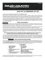
READ INSTRUCTIONS THOROUGHLY AND COMPLETELY BEFORE BEGINNING INSTALLATION.
INSTALLATION BY A CERTIFIED PROFESSIONAL MECHANIC IS HIGHLY RECOMMENDED.
READYLIFT® IS NOT RESPONSIBLE FOR ANY DAMAGE OR FAILURE RESULTING FROM IMPROPER INSTALLATION.
Safety Warning
MISUSE OF THIS PRODUCT COULD LEAD TO INJURY OR DEATH.
Suspension systems or components that enhance the on and off-road performance of your vehicle may cause
it to handle differently than it did from the factory. Extreme care must be used to prevent loss of control or
vehicle rollover during abrupt maneuvers.
Always operate your vehicle at reduced speeds to ensure your ability to control your vehicle under all driving
conditions. Failure to drive safely may result in serious injury or death to driver and passengers.
Driver and passengers must ALWAYS wear your seat belts, avoid quick sharp turns and other sudden
maneuvers. ReadyLIFT Suspension does not recommend the combined use of suspension lifts, body lifts, or
other lifting devices.
You should never operate your vehicle under the influence of alcohol or drugs.
Constant maintenance is required to keep your vehicle safe. Thoroughly inspect your vehicle before and after
every off-road use.
It is the responsibility of the retailer and/or the installer to review all state and local laws, with the end user
of this product, related to bumper height laws and the lifting of their vehicle before the purchase and
installation of any ReadyLIFT products.
It is the responsibility of the driver/s to check their surrounding area for obstructions, people, and animals
before moving the vehicle.
All raised vehicles have increased blind spots; damage, injury and/or death can occur if these instructions are
not followed.
.
Installation Warning
All steps and procedures described in these instructions were performed while the vehicle was properly
supported on a two post vehicle lift with safety jacks.
Use caution during all disassembly and assembly steps to insure suspension components are not over
extended causing damage to any vehicle components and parts included in this kit.
Included instructions are guidelines only for recommended procedures and are not meant to be definitive.
Installer is responsible to insure a safe and controllable vehicle after performing modifications.
ReadyLIFT Suspension recommends the use of an OE Service Manual for model/year of vehicle when
disassembly and assembly of factory and related components.
Unless otherwise specified, tighten all bolts and fasteners to standard torque specifications listed within the
OE Service Manual.
Suspension components that use rubber or urethane bushings should be tightened with the vehicle at normal
ride height. This will prevent premature wear or failure of the bushing and maintain ride comfort.
Larger tire and wheel combinations may increase leverage on suspension, steering, and related components.
Due to payload options and initial ride height variances, the amount of lift is a base figure. Final ride height
dimensions may vary in accordance to original vehicle ride height. Always measure the vehicle ride height
prior to beginning installation.

www.ReadyLIFT.com - Phone: (877) 759-9991
3 49-19610-IM-AA
Due to payload options and initial ride height variances, the amount of lift is a base figure. Final ride height
dimensions may vary in accordance to original vehicle ride height. Always measure the vehicle ride height
prior to beginning installation.
A lifted vehicle may have different headlight aim performance. ReadyLIFT recommends marking and
recording the headlight beam position before kit installation and then adjusting, if necessary, the headlamps
to the same height settings after kit installation. Set the vehicle on a level surface 10' to 15’ from a solid wall
or garage door. (This is a general distance with some manufacturers requiring different distances.) Note the
top height of the low beam's bright spot, the top of the most intense part of the beam, for driver and
passenger side. Height may vary from side to side. Repeat this procedure and adjust after lift kit is
installed. Adjust if the aim is off by turning the adjusters gradually (a quarter of a turn) and looking to see
where the new alignment falls. It may be easier to block one headlamp while adjusting the other. Consult
the owner operation manual for procedures to adjust headlights - many automakers offer headlight aiming
specs. Some states have their own specifications when it comes to headlight aim, so it’s best to follow those
rules when aligning headlights.
This suspension system was developed using a 37” x 13.5” tire with 20” x 9” wheel
and a offset of 0. If wider tires are used, offset wheels may be necessary and
trimming may be required. Factory wheels can be used but are not recommended
with tires over 11” wide.
The stock spare rim can be run in an emergency - exercise extreme caution under
stock spare tire operating conditions. Please note that, if running the spare factory
tire, it is done for short distances and a speed not to exceed 45mph or damage to
differentials may occur.
IMPORTANT NOTE:
Kit not compatible with other aftermarket lift springs or other lift
systems. Use of additional lift components may damage vehicle
and could result in injury or death.
SAEJ2492 Warning
By installing this product, you acknowledge that the suspension of this vehicle has been modified. As a result,
this vehicle may handle differently than that of factory equipped vehicles. As with any vehicle, extreme care
must be used to prevent loss of control or roll-over during sharp turns or abrupt maneuvers. Always wear
seat belts, and drive safely, recognizing that reduced speeds and specialized driving techniques may be
required. Failure to drive this vehicle safely may result in serious injury or death. Do not drive this vehicle
unless you are familiar with its unique handling characteristics and are confident of your ability to maintain
control under all driving conditions. Some modifications (and combinations of modifications) are not
recommended and may not be permitted in your state. Consult your owner’s manual, the instructions
accompanying this product, and state laws before undertaking these modifications. You are responsible for
the legality and safety of the vehicle you modify using these components.

www.ReadyLIFT.com - Phone: (877) 759-9991
4 49-19610-IM-AA
PRE-INSTALLATION MEASUREMENTS:
It is imperative that you record the following measurements and factory components
in the tables below. ReadyLIFT tests and records as much data from each application
as available at the time of product development. Vehicle manufacturers may change
components or add models with different options. Recording and not exceeding the
fender-to-hub-center ReadyLIFT calls out will ensure the lift on the vehicle is correct.
These measurements will affect the performance of this lift kit. Failure to ensure
proper stock conditions may result in over lifting, causing premature failure of axles,
CV boots and drivetrain. Over lifting a vehicle will also result in an incorrect wheel
alignment. This will wear tires incorrectly. Incorrect alignment will cause poor vehicle
handling issues including but not limited to under steer. Over lifting will also cause a
shock top off condition resulting in poor ride quality accompanied by pops and clunks
which are symptoms of prematurely wearing components.
Failure to adjust head lamps may cause dangerous driving conditions for you and
other drivers on the road. Record the head lamp position before the installation of this
lift or leveling kit and adjust to original factory position after the completion to ensure
a safe and enjoyable experience.
VEHICLE HEIGHT MEASURMENTS
**MEASUREMENT IS TO BE PERFORMED FROM CENTER OF HUB TO FENDER
EDGE STRAIGHT UP FROM HUB.**
RECORD HEAD LAMP MEASURMENTS
Driver
Before
Driver
After
Passenger
Before
Passenger
After
Front
Rear
Driver
Before
Driver
After
Passenger
Before
Passenger
After

www.ReadyLIFT.com - Phone: (877) 759-9991
5 49-19610-IM-AA
BILL OF MATERIALS
Before starting installation:
ReadyLIFT Suspension highly recommends that the installation of this
product be performed by a professional mechanic with experience working on and installing suspension
products. Professional knowledge and skill will typically yield the best installation results. If you need an
installer in your area, please contact ReadyLIFT Suspension Customer Service to find one of our
“Pro-Grade” Dealers.
INSTALLATION BY A PROFESSIONAL IS HIGHLY RECOMMENDED.
• A Factory Service Manual for your specific Year / Make / Model is highly recommended for reference
during installation.
• All lifted vehicles may require additional driveline modifications and / or balancing.
• A vehicle alignment is REQUIRED after installation of this product.
• Speedometer / Computer recalibration is required if changing +/- 10% from factory tire diameter.
• A vehicle lift or hoist greatly reduces installation time. Installation time estimates are based on an
• available vehicle hoist.
• Vehicle must be in excellent operating condition. Repair or replace any and all worn or damaged
components prior to installation.
Components
Coil Spring, Front 2
Coil Spring, Rear 2
Falcon Shock, Front 2
Falcon Shock, Rear 2
Radius Arm Drop Bracket 2
Radius Drop Bracket Nut Plate 4
Front Track Bar Bracket 1
Rear Track Bar Bracket 1
Driver Sway Bar Drop Bracket 1
Passenger Sway Bar Drop Bracket 1
14.25” Sway Bar Endlink 2
5” Front Bump Stop 2
Rear Bump Stop Extension 2
Pitman Arm Drop 1
Transmission Crossmember 1
Transmission Mounting Plate 1
Transmission Mount Spacer 2
Transmission Connector Bracket 1
Transmission Harness Bracket 1
6-Bolt Clocking Ring 1
Front Brake Line Bracket 2
Rear Brake Line Bracket 1
Pinch Clamp 1
Spring Isolator Retainer 2
Isolator Drill Template 1
Hardware
M12-1.75x45mm Bolt 6
M14-2.0x75mm Bolt 2
M14-2.0x35mm Bolt 1
M6-2.0x20mm 1
M10-1.5x30mm Hex Drive Flat Head 6
5/16"-18 x 1/2" HHB YZ Grade 8 6
Hardware
M6-1.0x25mm Bolt 1
M6-1.0 Locking Nut 2
M6 Washer 4
M8-1.25x20mm Bolt 2
M8-1.25 Locking Nut 2
M8 Washer 4
M10-1.5 Flat Head Screw 6
M12-1.75x70mm Bolt 2
M12-1.75 Locking Nut 8
M12 Washer 14
M12 Fender Washer 2
M14-2.0x100mm Bolt 1
M14-2.0 Locking Nut 3
M14 Washer 7
M18-2.5x130mm Bolt 2
M18-2.5 Locking Nut 2
M18 Washer 4
5/16”-18x1” Bolt 2
5/16”-18 Locking Nut 2
5/16” Washer 4
7/16”-14x1.25” Bolt 4
7/16”-14 Locking Nut 4
7/16” Washer 8
3/8”-16x1” Bolt 4
3/8”-16 Locking Nut 10
3/8” Washer 14
1/2”-13x1.25” Bolt 4
1/2” Washer 4

www.ReadyLIFT.com - Phone: (877) 759-9991
6 49-19610-IM-AA
***Parts shown in red for picture clarification only***
ReadyLIFT recommends all steps and procedures described in these instructions be
performed while the vehicle is properly supported on a two post vehicle lift with
safety jacks. Otherwise, park vehicle on a clean flat surface and block the rear wheels
for safety. Engage the parking brake.
Disconnect the vehicle power source at the ground terminal on the battery.
Lock the steering wheel in the straight forward position with the column lock or
steering wheel locking device.
Raise the front of the vehicle and support with safety jack stands. Remove the front
wheels. Starting with the front of the vehicle, all steps are to be completed on both
sides of the vehicle unless instructed.
Front Suspension Installation
Remove the (2) brake line/ABS brackets
on both sides of the vehicle attached to
the axle and radius arm.
Retain factory hardware.
Locate the brake line/ABS bracket on the
inside of the driver and passenger frame
rails and remove.
Retain factory hardware.

www.ReadyLIFT.com - Phone: (877) 759-9991
7 49-19610-IM-AA
Loosen but do not remove the lower
shock mounting bolts.
Place a jack under the axle for support.
Remove the radius arm bolts.
Retain factory hardware.
Mark the driveshaft to pinion location.
Remove the (4) front driveshaft bolts.
Remove the front driveshaft from the axle.
Let hang out of the way.
Retain factory hardware.
Rotate the axle to release radius arms
from the mounting locations.

www.ReadyLIFT.com - Phone: (877) 759-9991
8 49-19610-IM-AA
Locate and install the provided radius arm
drop brackets using the factory hardware
at the main mounting locations.
Do not tighten at this time.
Locate the (4) provided wire flag nuts and
the (4) holes on the outside of the frame.
Bend the wires to align the tab nut with
the rear mounting holes in the bracket
and frame.
Once lined up with the lower mounting
holes, install the provided 1/2” bolts and
washers.
Do not tighten at this time.
Bend the wires to align the tab nut with
the front mounting holes in the bracket
and frame. Install the provided 1/2” bolts
and washers.
Do not tighten at this time.

www.ReadyLIFT.com - Phone: (877) 759-9991
9 49-19610-IM-AA
Tighten the provided 1/2” bolts first,
ensure the drop bracket is resting flush
against the frame rail when doing so.
Torque to 80 ft-lbs.
Rotate the axle until the radius arms are
lined back up into the drop brackets.
Install using the provided M18 hardware.
Do not tighten at this time.
Supporting the axle with a suitable jack,
remove the front shocks and discard
properly.
Remove the (2) brake line bracket bolts
on both sides of the vehicle attached to
the inside of the upper frame.
Retain factory hardware.

www.ReadyLIFT.com - Phone: (877) 759-9991
10 49-19610-IM-AA
Remove the tie rod end nut. Strike the
pitman arm tie rod boss with a dead blow
hammer to dislodge the taper. Remove
the tie rod end from the pitman arm and
let hang out of the way.
Remove the pitman arm nut. Using a
pitman arm puller, remove the pitman
arm from the steering box sector shaft.
Note: Be sure to thoroughly clean splines
prior to installing pitman arm
replacement.
Locate and install the provided drop
pitman arm in the factory orientation
using factory hardware and thread locker.
Loosen tie rod end adjuster and rotate tie
rod end 180 degrees. Attach tie rod end
to pitman arm using factory hardware.
Rotate the steering all the way to
the right until hubs are resting on the turn
stops.
Torque pitman arm nut to 177 ft-lbs.
Torque the tie rod end to 100 ft-lbs.

www.ReadyLIFT.com - Phone: (877) 759-9991
11 49-19610-IM-AA
Loosen but do not remove track bar bolt
at the axle.
Remove track bar hardware at the frame
and swing track bar out of the way.
Retain factory hardware.
Lower the axle enough to remove the coil
springs from their mounts and discard.
Be sure to retain the factory spring
isolators.
Remove the (5) factory mounting bolts
from the factory track bar bracket and
remove from vehicle.
Retain factory hardware.

www.ReadyLIFT.com - Phone: (877) 759-9991
12 49-19610-IM-AA
Install provided track bar drop bracket
using factory hardware and provided M14
hardware.
Torque to 110 ft-lbs.
Install track bar using factory hardware.
Do not tighten at this time.
Remove the factory bump stops.
Install the provided extended bump stops.
To aid in install, lube the mounting end
with a soap and water mix.

www.ReadyLIFT.com - Phone: (877) 759-9991
13 49-19610-IM-AA
Using the supplied drill template, align the
corresponding hole with the correct side.
“D” will line up with the factory driver side
hole and the “P” will line up with the
passenger side hole.
Using a marker or paint marker, Mark the
location of the small hole. This is to be
where you will drill the new mounting
hole.
Center punch the marks and using an
appropriate tool, drill the 1/2” holes
through the spring tower.
Paint the cut surface to prevent any
corrosion.
NOTE: USE CAUTION WHEN DRILLING
THROUGH AS THERE ARE VITAL SAFETY
SYSTEMS ON THE OTHER SIDE THAT CAN BE
DAMAGED IF CARE ISN’T TAKEN WHILE
DRILLING.
Using thread locker install the (3) supplied
5/16” bolt from the inside out on the
supplied spring isolator retainer.
Install the supplied spring isolator retainer
into the factory isolator boss.

www.ReadyLIFT.com - Phone: (877) 759-9991
14 49-19610-IM-AA
Tighten the (3) 5/16” bolts until tight.
Torque the bolts to 35 ft-lbs.
Install spring isolator over the retainer,
ensure the alignment tab is installed into
new clocking hole.
NOTE: FOR CLARIFICATION PURPOSES THE
SPRING ISOLATOR RETAINER IS NOT SHOWN
IN PHOTO.
Install the provided coil springs with
factory isolators on top. Make sure the
isolator is positioned on the flat end of the
coil spring. Lower the axle low enough to
set both springs in place.
Install the provided Falcon front shock
into the upper frame mount using the
provided hardware.
Torque to 45 ft-lbs

www.ReadyLIFT.com - Phone: (877) 759-9991
15 49-19610-IM-AA
Install the Falcon front shock lower mount
to the axle mount using the factory
hardware.
Do not tighten at this time.
You will now be able to install the sway
bar end link while lifting the axle into
place.
Make sure to align the springs with each
spring perch as you go up.
Install the (2) 18mm sway bar end link
nut.
Torque to 50 ft-lbs.
Remove the (4) sway bar bracket bolts
and let the sway bar hang out of the way.
Install the sway bar drop brackets to the
frame using the factory hardware.
Note: You should be able to read the
Readylift R from either side of the vehicle
normally.

www.ReadyLIFT.com - Phone: (877) 759-9991
16 49-19610-IM-AA
Install the sway bar to the drop brackets
using the provided 7/16” hardware.
Torque factory hardware to 50 ft-lbs.
Torque the 7/16” hardware to 50 ft-lbs.
Install provided brake line extensions to
the frame brake line brackets using the
provided 5/16” hardware.
Do not tighten at this time.
Attach provided extension bracket to the
inside frame rail using the factory
hardware. It will be necessary to gently
pull down and bend the metal brake line
on the driver side to gain the slack
needed.
The passenger side bracket will angle
around the frame gusset.
Torque to 15 ft-lbs.
Install the (2) ABS sensor harness and
brake line brackets to the radius arm
using factory hardware.
Torque to 10 ft-lbs.

www.ReadyLIFT.com - Phone: (877) 759-9991
17 49-19610-IM-AA
***Parts shown in red for picture clarification only***
Clocking Ring and Transmission Crossmember Installation
Using a suitable jack, support the transfer
case. Allow yourself ample room around
the front of the transfer case to ensure
you have room to access hardware and
harnesses.
With the transfer case supported, locate
the (3) transmission mounting nuts.
Install the (2) ABS brackets to the axle
using factory hardware.
Torque to 10 ft-lbs.

www.ReadyLIFT.com - Phone: (877) 759-9991
18 49-19610-IM-AA
Remove the (3) transmission mounting
nuts.
Retain factory hardware.
Remove the harness mounting clips
attached to the front of the transmission
crossmember.
Support the transmission crossmember
with a suitable jack stand. Working on one
side at a time, Loosen and remove two
transmission crossmember bolts.
Retain factory hardware.
Note: For the vehicles that have their
passenger crossmember bolts facing the
wrong way from factory follow the next
seven steps. If not then skip the next few
steps.
Remove the (3) front exhaust hanger
mounting bolts.
Retain factory hardware.

www.ReadyLIFT.com - Phone: (877) 759-9991
19 49-19610-IM-AA
Remove the (2) center exhaust hanger
mounting bolts.
Retain factory hardware.
Remove the (2) Diesel Exhaust Fluid
(DEF) tank crossmember exhaust hanger
mounting bolts.
Retain factory hardware.
Raise the DPF with a suitable jack and
remove the (2) passenger transmission
crossmember bolts.
Retain factory hardware.
Lower jack and install the (2) Diesel
Exhaust Fluid (DEF) tank crossmember
exhaust hanger bolts.
Torque to 15 ft-lbs.

www.ReadyLIFT.com - Phone: (877) 759-9991
20 49-19610-IM-AA
Install the (2) center exhaust hanger
mounting bolts.
Torque the mounting bolts to 20 ft-lbs.
Install the (3) front exhaust hanger
mounting bolts.
Torque the mounting bolts to 20 ft-lbs.
Make sure that the factory radius arm bolt
is still loose to aid in the removal of the
transmission crossmember.
Remove the (4) transmission
crossmember bolts and retain factory
hardware.
Ensure all transmission crossmember
hardware or harnesses are clear and
remove the transmission crossmember.
/