Maxon SP-200K Series User manual
- Category
- Two-way radios
- Type
- User manual

SP-200K Series
Synthesized Scanning Radio
Operating
Instructions

i
Table of Contents
I. FCC RF Exposure Compliance Requirements for
Occupational Use Only................................................................................ 1
II. Safety Information........................................................................................... 1
III. About Your SP-200K Series Radio................................................................... 2
IV. About Topaz3.................................................................................................. 2
V. Unpacking Information.................................................................................... 3
VI. SP-200K Series Features.................................................................................. 4
VII. Description of Radio Components................................................................... 5
VIII. Antenna Installation......................................................................................... 6
IX. Installing and Removing the Battery Pack....................................................... 6
X. Attaching and Removing the Belt Clip............................................................. 6
XI. Battery Charging and Care.............................................................................. 6
XII. SP-200K Series Operation............................................................................... 7
Power On - Volume - Power Off.................................................................. 7
Channel Select /Channel Group Scan........................................................... 7
To Transmit................................................................................................... 7
To Receive................................................................................................... 9
Keypad Lock / Function Lock ...................................................................... 9
XIII. Status Indicators and Audible Alert Tones........................................................ 9
XIV. Scan Modes..................................................................................................... 10
Normal Channel Scan................................................................................... 10
Priority Channel Scan................................................................................... 11
XV. Other Scanning Features................................................................................. 11
Look Back.................................................................................................... 11
Scan Channel Delete.................................................................................... 11
CTCSS / DCS Scanning................................................................................ 12
Normal Scan TX............................................................................................ 12
Priority Scan TX............................................................................................ 12
Priority Only TX........................................................................................... 12
Receive Only Scan....................................................................................... 12
XVI. Scan List Edit.................................................................................................... 12
Channel Group Edit...................................................................................... 12
Priority Channel Edit..................................................................................... 13
XVII. Possible Set-ups for the SP-200K Series........................................................... 14
XVIII. Compatible SP-200K / SP-210K Accessories..................................................... 16
XIX. FCC Licensing.................................................................................................. 16
XX. Service............................................................................................................ 17
XXI. Software Copyrights........................................................................................ 17
XXII. Maintenance.................................................................................................... 17
XXIII. Product Warranty............................................................................................ 18
Page is loading ...
Page is loading ...

1
I. FCC RF Exposure Compliance Requirements for Occupational Use Only
The Federal Communications Commission (FCC), with its action in General
Docket 93-62, November 7, 1997, has adopted a safety standard for human
exposure to Radio Frequency (RF) electromagnetic energy emitted by FCC
regulated equipment. Topaz3 / Maxon subscribes to the same safety standard
for the use of its products. Proper operation of this radio will result in user
exposure far below the Occupational Safety and Health Act (OSHA) and
Federal Communications Commission limits.
CAUTION - DO NOT transmit for more than 50% of total radio use time (50%
duty cycle). Transmitting more than 50% of the time can cause
FCC RF exposure compliance requirements to be exceeded.
• This radio is NOT approved for use by the general population in an
uncontrolled environment. This radio is restricted to occupational use,
work related operations only where radio operator must have the knowledge
to control the users exposure conditions for satisfying the higher exposure
limit allowed for occupational use.
• When transmitting, hold the radio in a vertical position with its microphone
2 inches (5 cm) away from your mouth.
• This device has been approved for use, at a maximum duty factor of 50%,
using the specific belt clip and leather belt-holster tested for body-worn SAR
compliance. Other belt clips or body-worn accessories may not comply and
should be avoided.
• The radio is transmitting when the red LED on the front of the radio is
illuminated. You can cause the radio to transmit by pressing the P-T-T bar
on the radio.
• These are required operating configurations for meeting FCC RF exposure
compliance. Failure to observe these restrictions mean violation.
II. Safety Information
WARNING - DO NOT hold the radio in such a manner that the antenna is next
to, or touching, exposed parts of the body, especially the face or
eyes, while transmitting.
WARNING - DO NOT allow children to operate transmitter-equipped radio
equipment.
CAUTION - DO NOT operate the radio near unshielded electrical blasting caps
or in an explosive atmosphere, unless it is a type especially designed
and qualified for such use.
CAUTION - DO NOT press and hold the transmit bar (P-T-T) when not actually
wishing to transmit.

2
III. About Your SP-200K Series Radio
Maxon's SP-200K (VHF) and SP-210K (UHF) synthesized radios with DTMF
keypad feature up to 13 scan groups with up to 16 channels per group for a
total capacity of 199 channels.
To assure satisfaction from the radio, we urge you to thoroughly read the
operation and function information in this manual before operating your
SP-200K Series.
Application of some of the functions described in this manual are determined
by the system you use. Your radio communications Dealer will program your
radio so that you have the greatest number of functions possible relative to
your needs.
Should you have questions regarding the operation of the radio, please
consult your radio communications Dealer.
IV. About Topaz3
Topaz3 is the exclusive supplier of Maxon®, Legacy and TruTalk brand
communication products.
Our product line ranges from FCC licensed two-way radios suitable for
Business and Industry (B&I) markets like farm, government, law enforcement,
utility, etc. to consumer communications equipment for recreational and
light-duty business markets.
Product offerings include a variety of UHF and VHF handheld and mobile
radios, repeaters and RF link modules as well as FRS (Family Radio Service),
GMRS (General Mobile Radio Service) radios, MURS (Multi User Radio Service)
radios, Citizens Band radios and weather monitors.
Available accessory items include a variety of carrying cases, spare batteries,
desktop and mobile chargers, ear bud speaker microphones and more for
each radio model.
For additional information on our product line, visit our
website: www.topaz3.com

V. Unpacking Information
Remove and carefully inspect the contents of your package(s) for the following
items:
Radio
Battery Pack
Battery Charger
Battery Charger Power Supply
Antenna
Belt Clip
Operating Instructions
If any items are missing, please contact the radio communications Dealer from
which you purchased the radio, or contact the Topaz3 Customer Service
Department, 1-800-821-7848, Ext. 499.
3

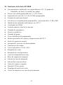
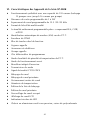
VI. SP-200K Series Features
Synthesized operation with 199 channel capability (13 scan
groups with up to 16 channels per group)
1 or 5 W programmable output power
Programmable 12.5 /20 /25 kHz channel spacing
Multi-tone Selcall format
Fully programmable tone sets - including EEA, CCIR, and ZVEI
Automatic Number Identification (ANI) on P-T-T
DTMF Encoder
Dual function keypad
Emergency calling
Stun and revive
Group calling
Programmer definable keys
Optional penalty modes and P-T-T time-out
Covert mode of operation
Built-in inversion scrambler
Status transmission
CTCSS/DCS Tone signaling
Channel scan
Priority channel scan
Look back channel
Time-out timer
Scan list edit
Priority channel edit
Busy channel lockout
LCD Channel display
Tri-color LED indicator
Die-cast aluminum chassis, polycarbonate case
4

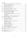
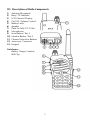
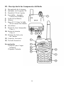
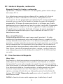
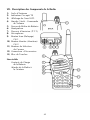
VII. Description of Radio Components
1) Antenna Receptacle
2) Busy / TX Indicator
3) LCD Channel Display
4) On/Off - Volume Control
5) Battery Latch
6) Speaker
7) Push-To-Talk (P-T-T) Bar
8) Microphone
9) Scan Button / Key 1
10) Monitor Button / Key 2
11) Channel Selection Buttons
12) Accessory Connector
13) Keypad
Not shown:
Battery Charge Contacts
Belt Clip
5

6
VIII. Antenna Installation
Fasten the antenna to the radio by turning the antenna clockwise into the
receptacle on top of the radio.
IX. Installing and Removing the Battery Pack
To attach the battery pack, hold the radio face down in your hand and
position the guides of the battery in line with the radio guide rails. Slide the
battery upward until a click is heard. To remove the battery pack, hold the
radio face down in your hand and push the battery latch button located in
the upper right hand corner of the battery pack. Hold the battery latch button
down, and slide the radio battery in a downward direction. Gently lift the
battery pack away from the base of radio when it is free from the radio guide
rails.
X. Attaching and Removing the Belt Clip
To attach the clip, hold the radio face down in your hand. Locate the slot in
the belt clip and align with holder on upper left hand corner of the radio back.
Push upward on belt clip until a click is heard. To remove the clip, push and
hold the release button located at the top of the belt clip. Slide the clip away
from the belt clip holder.
XI. Battery Charging and Care
Before initial operation, use the provided charger to completely charge the
radio battery pack. Remove the charger base and power supply from the
packaging, and plug in the power supply's DC connector into a jack on
the back of the charging base. Plug the AC power cord into any standard
110V AC outlet.
To charge a battery while attached to a radio, simply place the radio into the
front charging well. The charger will identify the battery condition, and then
automatically initiate a charge mode - rapid or top-off / trickle.
To charge a battery removed from the radio, place the battery into the rear
charging well. Again, the charger will identify the battery condition, and
automatically rapid charge or top-off / trickle charge the battery pack. Note
the color of the LED charge indicators: red for rapid charge cycle, green for
the top-off / trickle charge cycle.

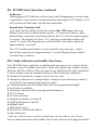
XI. Battery Charging and Care, continued
When using both charging wells, only one can rapid charge at a time. The
front charging well always has priority for rapid charging. After the front well
cycles from rapid to top-off / trickle charge, the back well will initiate its rapid
charge mode. Again, note the color of the charging well's LED to define the
current charging cycle.
NOTE: To ensure peak performance from your radio, periodically discharge
the battery completely and recharge fully. This action will prevent the battery
from developing a "memory" of short-term use, and will permit a good service
life.
XII. SP-200K Series Operation
Many of the features of the SP-200K Series are defined by you and will have
been determined by your radio communications Dealer and yourself. Refer to
Possible Set-ups for the SP-200K Series on how your radio may have been
programmed.
Power On - Volume - Power Off
Turn the radio on by rotating the off / on - volume control clockwise. You
will hear a click and (if enabled via Dealer programming), the radio's self-test
alert tones. Increase the radio volume by continuing the clockwise rotation.
To turn the radio off when you have finished transmitting, receiving, etc.,
rotate the control counter-clockwise to detent.
Channel Select / Channel Group Scan
To change radio channels, simply press and release the I or J button
until the desired channel is reached. Or, to scroll through your programmed
channels more quickly, press and hold the I or J button. The channel
numbers will appear in the radio's LCD (located at top of unit).
If your radio has been programmed for channel group scan, you must enter
the scan mode by pressing the scan button (first button below the P-T-T bar).
The current channel group will display on the radio's LCD. If you wish to
change that selection, use the I or J button, until the LCD displays the
channel group you wish to scan.
To Transmit
NOTE: The Federal Communications Commission Rules and Regulations
require that you monitor a channel for activity before transmitting, to avoid
interrupting another user.
7

8
XII. SP-200K Series Operation, continued
To Transmit, continued
Standard Transmit: Press the monitor button (second button below the
P-T-T bar) and check the color of the radio's top-panel LED. It will glow
orange if RF activity is present; it will not be illuminated if the radio indicates
a "clear" channel.
The following comments are intended to be used as a guide only, due to
the variable nature of the software and radio features.
Transmit a fixed Selcall address: A short or long press on a Call Key, either
Key 1 or Key 2 depending on set-up. Briefly the LED on the top panel
illuminates red. Conversation can begin by pressing the P-T-T button.
Transmit a variable Selcall address: A variable Selcall address may be
selected using the numerical keys (0 - 9). The number of variable digits will
be determined at programming. Pressing the * key generates the default
address (Call 1) with appended variable digits. Pressing the # key generates
the default address (Call 2) with appended variable digits.
At power-up, the radio will default to Selcall mode.
To Transmit DTMF: The radio can be programmed for DTMF transmission
only, or can be programmed to toggle between Selcall and DTMF. If
programmed with this "toggle keypad" mode, press the "toggle keypad"
key (defined at programming stage) and press the DTMF keys to transmit.
Pressing the "toggle keypad" key once more will return the keypad to Selcall
mode. In DTMF mode only, press the DTMF keys to transmit.
With all of the above features, when the channel is "clear", hold the radio
microphone area approximately 2 inches from your mouth, keeping the
antenna vertical and away from face or eyes. Press and hold the P-T-T bar
on the side of the radio, and begin speaking in a clear, normal tone. Release
the P-T-T bar when you have finished speaking.
CAUTION: Operation of the transmitter without a proper antenna installed
may result in permanent damage to the radio.
NOTE: The radio's LED will glow red continuously when you have the P-T-T
bar pressed and are transmitting. If the red LED starts "flashing", the battery
needs to be recharged and transmission will cease. Recharge the battery
fully before attempting more than one transmission.

XII. SP-200K Series Operation, continued
To Receive
Flashing green LED indicates call received, and if programmed, an alert tone
is generated. Conversation can then begin by pressing the P-T-T button. LED
will continue to flash until call has been answered.
Keypad Lock / Function Lock
Your radio has the ability to lock the channel I or J buttons and scan
button to prevent accidental button presses. To lock these buttons, press
and hold the scan button (first button below the P-T-T bar) for approximately
4 seconds. The display will show "LO" and two confirmation beeps will
sound. To unlock the keypad, press and hold the scan button again for
approximately 4 seconds.
The P-T-T and monitor buttons can be locked by pressing the * and #
keys at the same time for approximately 1 second. Repeat the procedure
tounlock these buttons.
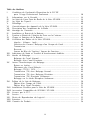
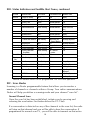
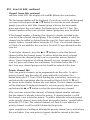
XIII. Status Indicators and Audible Alert Tones
Your SP-200K Series radio has a sophisticated microprocessor control which
provides a series of audible alert tones. Upon each power-up, a quick melody*
indicates that the self-test of the microprocessor functions has been completed.
A series of tones may be sounded with any of the following conditions:
Attempt to transmit on a channel set for receive only
Attempt to transmit on a channel that is already in use when busy channel
lockout has been programmed into the radio*
Transmitting time has exceeded time-out timer programmed length*
Low battery condition
Selecting a channel with no programmed frequency
P-T-T lockout
TX Time-out-timer
Toggling scrambler on and off
Toggling keypad on and off
Keypad alerts
Side button alerts
Decode of valid Selcall address
Auto-mute alert
* Indicates a function that is initially programmed into the radio by your Dealer.
See the Status Indicators and Audible Alert Tones chart on next page for details.
9

XIV. Scan Modes
Scanning is a Dealer programmable feature that allows you to monitor a
number of channels or channels within a Group. Your radio communications
Dealer will help you define a scanning mode and your channel "scan list" .
Normal Channel Scan
Once the scan list has been established, initiate scan by pressing and
releasing the scan button (first button below the P-T-T bar).
If a conversation is detected on any of the channels in the scan list, the radio
will stop on that channel and you will be able to hear the conversation. If
programmed for normal scan TX, you will be able to transmit on that active
10
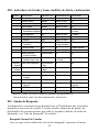
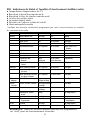
STATUS DESCRIPTION LED COLOR LCD INDICATION AUDIBLE TONE
Normal Power On - Ready N/A 188 Melody
Call Received Orange Channel Number N/A
Correct Call Green Channel Number N/A
Busy Channel Orange Channel Number N/A
Valid Selcall Decode Green Flashing Channel Number One to Three Tone
Alert
Radio Stunned N/A Channel Number Two Beeps
Radio Received N/A Channel Number Melody
Transmit Red Channel Number N/A
Transmit Not Allowed Red Flashing Alternating UL / Two Beeps Repeated
Channel Number
Keypad Lock N/A LO Two Beeps Repeated
Scanning Normal Scan Mode Green Flashing Group Number N/A
Priority Scan Mode Green Flashing N/A N/A
Priority Look Back Green Flashing Lb / Channel N/A
Scan Mode number
Scan Edit Edit Scan List Red Single Flash SE N/ A
Priority Edit Priority Channel Red Two Flashes PE N/A
Edit
Warning Low Battery Red Flashing LC 3 Beeps Repeated
Busy Channel Lockout Orange bL Single Beep Repeated
TX Inhibit N/A _h/rO Two Beeps
Time-Out-Timer N/A Pt Single Beep/3 Beeps
Repeated
Error EEPROM N/A Er Single Beep Repeated
Unlock N/A UL Two Beeps Repeated
NOTE: All audible tones can be programmed "off" for silent operation.
XIII. Status Indicators and Audible Alert Tones, continued

11
XIV. Scan Modes, continued
Normal Channel Scan, continued
channel during the programmable scan delay time. (The scan delay time
is the amount of time the radio will stay on that channel once activity has
ceased. Dealer programmable, 4-7 seconds is typical). The radio will
resume scanning once the scan delay time has expired, and will continue
to scan until the channel is changed. The LED will flash green.
Priority Channel Scan
A single channel may be programmed as the "Priority" channel. The radio
will constantly monitor this channel while scanning and when the radio has
stopped on an active channel. If a call is detected on the priority channel,
the radio will automatically move to, and remain on, the priority channel
for as long as the priority conversation takes place. Priority channel activity
takes precedence over all other conversations. To activate the Priority scan
mode, press and release the scan button (first button below the P-T-T bar).
The LED will flash green.
XV. Other Scanning Features
Look Back
This feature is ideal for those who do not need scan as defined above, but
want to make sure that they never miss a call on the "Priority" channel if
another channel has been selected. Once a channel has been selected,
the radio will periodically "look back" at the priority channel. If activity is
detected on the priority channel, the radio will move to that channel for
as long as it remains active. To enter the "look back" mode, press and hold
the scan button (first button below the P-T-T bar). Lb / Channel number will
be shown in the display, the LED will flash green.
NOTE: Look back requires that the radio leave the current channel for a
fraction of a second (at regular intervals) to check the priority channel for
activity. Depending upon how the radio is programmed (scan speed, etc.)
this may or may not be noticeable as "breaks" on the current channel for
that same fraction of a second. A transmission will be made on the active
channel at all times.
Scan Channel Delete
To temporarily delete a channel from the scan list, simply press the monitor
button (second button below the P-T-T bar) while scanning and stopped on
the channel to be deleted. This will remove that channel from the scan list

XV. Other Scanning Features, continued
Scan Channel Delete, continued
until the channel is changed or the radio's power is reset. When power is
restored or the scan list channel position is selected again, the originally
programmed scan list will be activated.
CTCSS / DCS Scanning
To help block out unwanted calls to your radio, the SP-200K Series can be
programmed by your Dealer to scan for tones.
Normal Scan TX
Allows a transmission only after a call is received, depending on the
programmed scan delay time. After scan resumes, and a transmission is
made, the radio will sound two beeps, display _h and will not allow a
transmission.
Priority Scan TX
Allows a transmission after a call is received depending on programmed
scan delay time. The transmission will be made on the channel that the call
was received. After the scan resumes, if a transmission is made, the radio
will transmit on the programmed priority channel.
Priority Only TX
Allows a transmission on the priority channel when scanning and not
stopped on an active channel. It will always transmit on the priority
channel if scanning or stopped on an active channel.
Receive Only Scan
This allows only reception, not transmission. If a transmission is made at
any time, the radio will sound two beeps, display r0 and will not allow the
transmission.
XVI. Scan List Edit
You can edit your radio's original scan list and priority scan channel at any
time. Please note, if your radio has been programmed for channel-only scan,
you will not be able to edit your scan list, only your priority channel.
Channel Group Edit
To edit the group scan list in a radio programmed for channel group scan,
turn the radio off, press and hold scan button, (first button below the P-T-T
bar). While holding scan button, turn the radio on, and observe a single
12

XVI. Scan List Edit, continued
Channel Group Edit, continued
red flash of the LED. The display will read SE. Release the scan button.
The first group number will be displayed. If you do not wish to edit the group
you have selected press the I or J button to select the desired channel
groups you wish to edit. After channel group selection has been made,
press and release the scan button (first button below the P-T-T bar). The
channel number within your selected channel group may now be edited.
If the channel number is flashing, that channel is already included in the
scan list of the selected channel group. If the channel number is solid, the
channel can be added or deleted from the scan list. Press and release the
monitor button, (second button below the P-T-T bar), the selected channel
will flash if it was added to the scan list or be solid if it was deleted from the
scan list.
To edit other channels, press the I or J buttons to select the desired
channel within the channel group. To add or delete the newly selected
channel from the channel group scan list, repeat the process detailed
above. Upon completion of editing channels on your channel group
scan list, press and release the scan button, (first button below the P-T-T
bar). Your new channel group scan list should be entered at this time.
Priority Channel Edit
Only one priority channel can be programmed into the radio. To edit a
priority channel, turn the radio off, press and hold scan button (first
button below the P-T-T bar). While holding the scan button, turn radio on,
and release the scan button after the second red flash of the LED. PE will
be shown in the display. Release the scan button. The first channel number
will be displayed. If displayed channel is not your priority channel, press
and release the I or J button to select the desired priority channel.
After you have selected the channel, a flashing channel number indicates
that the channel is already selected as priority. If channel number is solid,
the channel is not selected as priority. To add or delete the selected channel
as the priority channel, press and release the monitor button, (second button
below the P-T-T bar). The selected channel will flash if it was added as a
priority channel or will be solid if deleted as the priority.
Upon completion of adding or deleting the priority channel, press and release
the scan button. Your new priority channel should be entered at this time.
13

14
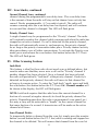
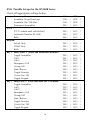
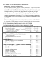
XVII. Possible Set-ups for the SP-200K Series
Check off appropriate settings below:
Power-up Alert ON ( ) OFF( )
Scrambler On at Power-up ON ( ) OFF( )
Scrambler On / Off Alert ON ( ) OFF( )
Permanent Scrambler YES ( ) NO ( )
P-T-T:
P-T-T Lockout until valid Selcall YES ( ) NO ( )
Automatic Number ID (ANI) YES ( ) NO ( )
Both YES ( ) NO ( )
Keypad:
Selcall Only YES ( ) NO ( )
DTMF Only YES ( ) NO ( )
Both YES ( ) NO ( )
Key 1 - Short Press = (Press and Immediate Release):
Toggle Scrambler YES ( ) NO ( )
Call 1 YES ( ) NO ( )
Call 2 YES ( ) NO ( )
Emergency Call YES ( ) NO ( )
Group Call YES ( ) NO ( )
Stun / Revive YES ( ) NO ( )
Toggle Monitor YES ( ) NO ( )
Covert On / Off YES ( ) NO ( )
Toggle Keypad YES ( ) NO ( )
Key 1 - Long Press = (Press and Hold for 2 Seconds):
Toggle Scrambler YES ( ) NO ( )
Call 1 YES ( ) NO ( )
Call 2 YES ( ) NO ( )
Emergency Call YES ( ) NO ( )
Group Call YES ( ) NO ( )
Stun / Revive YES ( ) NO ( )
Toggle Monitor YES ( ) NO ( )
Covert On / Off YES ( ) NO ( )
Toggle Keypad YES ( ) NO ( )

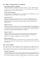
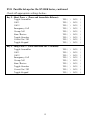
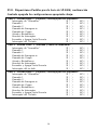
XVII. Possible Set-ups for the SP-200K Series, continued
Check off appropriate settings below:
Key 2 - Short Press = (Press and Immediate Release):
Toggle Scrambler YES ( ) NO ( )
Call 1 YES ( ) NO ( )
Call 2 YES ( ) NO ( )
Emergency Call YES ( ) NO ( )
Group Call YES ( ) NO ( )
Stun / Revive YES ( ) NO ( )
Toggle Monitor YES ( ) NO ( )
Covert On / Off YES ( ) NO ( )
Toggle Keypad YES ( ) NO ( )
Key 2 - Long Press = (Press and Hold for 2 Seconds):
Toggle Scrambler YES ( ) NO ( )
Call 1 YES ( ) NO ( )
Call 2 YES ( ) NO ( )
Emergency Call YES ( ) NO ( )
Group Call YES ( ) NO ( )
Stun / Revive YES ( ) NO ( )
Toggle Monitor YES ( ) NO ( )
Covert On / Off YES ( ) NO ( )
Toggle Keypad YES ( ) NO ( )
15

16
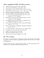
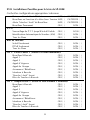
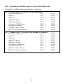
XVIII. Compatible SP-200K / SP-210K Accessories
900 mAh Prismatic battery pack (QPA-900)
1350 mAh NiMH Battery pack (QPA-1350)
VHF Antenna, uncut, 148-174 MHz, SMA (ACC-102)
UHF Antenna, 440-470 MHz, 3-1/2" , SMA (ACC-100)
Dual slot / dual rate desktop charger (ACC-400K)
Ultra-lite headset with locking connector (ACC-616)
Over-the-head noise-attenuating headset (ACC-626)
(requires ACC-506 adaptor)
Behind-the-head noise-attenuating headset (ACC-627)
(requires ACC-506 adaptor )
Ear bud speaker with in-line P-T-T, microphone and
locking connector (ACC-706)
Lapel speaker microphone with ear jack and locking
connector (ACC-726)
Heavy Duty speaker microphone with audio earphone
jack (ACC-727)
Coil-cord earphone, used with ACC-727 (QPA-1424)
Ear speaker, for use with ACC-726 (WTA-9F)
Leather case with swivel (ACC-300)
Nylon case with belt clip (ACC-301)
2-pin to 1-pin Accessory adaptor (ACC-506)
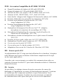
XIX. FCC Licensing
The Federal Communications Commission requires the operator of this radio
be properly licensed under the applicable Part and/or Parts of the FCC Rules
and Regulations.
Consult with your radio communications Dealer, or contact the nearest FCC
field office for information about obtaining a license.

XX. Service
Do not tamper with internal adjustments. Damage to the equipment and/or
improper operation may result. There are no serviceable items inside the
radio. It is recommended that you return your radio to a qualified radio
communications Dealer for any service or repairs.
XXI. Software Copyrights
The Topaz3 / Maxon product(s) described in these operating instructions
may include copyrighted Topaz3 / Maxon software programs stored in
semi-conductor memories or other media. Laws in the United States and other
countries preserve for Topaz3 / Maxon certain exclusive rights for copyrighted
software programs, including the exclusive right to copy or reproduce in any
form the copyrighted software program.
Accordingly, the copyrighted Topaz3 / Maxon software programs contained in
the Topaz3 / Maxon products described in this operating manual may not be
copied or reproduced without the express written permission of Topaz3, LLC.
Furthermore, the purchase of Topaz3 / Maxon products shall not be deemed to
grant either directly or by implication, estoppel, or otherwise, any license under
the copyrights, patents or patent applications of Topaz3, LLC, except for normal
non-exclusive, royalty-free license to use that arises by operation of law in the
sale of a product.
XXII. Maintenance
Your SP-200K Series radio is designed to be maintenance free. To keep your
radio in good working condition, follow these cleaning instructions:
Clean external surfaces with a clean cloth dampened in a solution of mild
dishwater detergent diluted in water. Apply the solution sparingly to avoid any
moisture leaking into cracks and crevices. DO NOT submerge the radio. Use
only a non-metallic brush to dislodge particles, if necessary. Dry the surface
thoroughly with a soft, lint-free cloth.
DO NOT use solvents or spirits for cleaning - they may permanently damage
the housing.
Clean the battery and accessory port contacts with a lint-free cloth to remove
dirt, grease or foreign materials that may impede good electrical contact.
17

18
XXIII. Product Warranty
Topaz3, LLC (herein Topaz3), warrants each new radio product manufactured or supplied by it
to be free from defects in material and workmanship under normal use and service for the time
period listed below, provided that the user has complied with the requirements stated herein. The
Warranty period begins on the date of purchase from an Authorized Topaz3 Sales and Service
Outlet. This Warranty is offered to the original end user and is not assignable or transferable.
Topaz3 is not responsible for any ancillary equipment which is attached to or used in conjunction
with Maxon and Legacy products.
Topaz3 offers to the original end user a Two (2) Year Limited Warranty on all Maxon and Legacy
Business and Industrial Radio Products. Accessories carry a One (1) Year Limited Warranty.
During this period, if the product fails to function under normal use because of manufacturing
defect(s) or workmanship, it should be returned to the Authorized Topaz3 Sales and Service Outlet
from which it was purchased. The Sales and Service Outlet will repair the product, or return the
product for repair to Topaz3 or its Authorized Repair Depot. The user is responsible for the payment
of any charges or expenses incurred for the removal of the defective product from the vehicle or
other site of its use; for the transportation of the product to the Sales and Service Outlet; for the
return of the repaired / replacement product to the site of its use and for the reinstallation of the
product.
Topaz3 shall have no obligation to make repairs or to cause replacement required which results
from normal wear and tear or is necessitated in whole or in part by catastrophe, fault or negligence
of the user, improper or unauthorized alterations or repairs to the Product, incorrect wiring, use of
the Product in a manner for which it was not designed, or by causes external to the Product.
This warranty is void if the product serial number is altered, defaced or removed.
Topaz3's sole obligation hereunder shall be to replace or repair the Product covered in this
Warranty. Replacement, at Topaz3's option, may include a similar or higher-featured product.
Repair may include the replacement of parts or boards with functionally equivalent reconditioned
or new parts or boards. Replaced parts, accessories, batteries or boards are warranted for the
balance of the original time period. All replaced parts, accessories, batteries or boards become
the property of Topaz3.
THE EXPRESS WARRANTIES CONTAINED HEREIN ARE IN LIEU OF ALL OTHER
WARRANTIES, EITHER EXPRESSED OR IMPLIED OR STATUTORY, INCLUDING, WITHOUT
LIMITATION, ANY WARRANTY OF MERCHANTABILITY OR FITNESS FOR A PARTICULAR
PURPOSE.
FOR ANY PRODUCT WHICH DOES NOT COMPLY WITH THE WARRANTY SPECIFIED, THE
SOLE REMEDY WILL BE REPAIR OR REPLACEMENT. IN NO EVENT WILL TOPAZ3 BE
LIABLE TO THE BUYER OR ITS CUSTOMERS FOR ANY DAMAGES, INCLUDING ANY
SPECIAL, INCIDENTAL, INDIRECT OR CONSEQUENTIAL DAMAGES, OR THE LOSS OF
PROFIT, REVENUE OR DATA ARISING OUT OF THE USE OF OR THE INABILITY TO USE
THE PRODUCT.
This Warranty is void for sales and deliveries outside of the U.S.A. or Canada.
Page is loading ...
Page is loading ...
Page is loading ...
Page is loading ...
Page is loading ...
Page is loading ...
Page is loading ...
Page is loading ...
Page is loading ...
Page is loading ...
Page is loading ...
Page is loading ...
Page is loading ...
Page is loading ...
Page is loading ...
Page is loading ...
Page is loading ...
Page is loading ...
Page is loading ...
Page is loading ...
Page is loading ...
Page is loading ...
Page is loading ...
Page is loading ...
Page is loading ...
Page is loading ...
Page is loading ...
Page is loading ...
Page is loading ...
Page is loading ...
Page is loading ...
Page is loading ...
Page is loading ...
Page is loading ...
Page is loading ...
Page is loading ...
Page is loading ...
Page is loading ...
Page is loading ...
Page is loading ...
Page is loading ...
Page is loading ...
-
 1
1
-
 2
2
-
 3
3
-
 4
4
-
 5
5
-
 6
6
-
 7
7
-
 8
8
-
 9
9
-
 10
10
-
 11
11
-
 12
12
-
 13
13
-
 14
14
-
 15
15
-
 16
16
-
 17
17
-
 18
18
-
 19
19
-
 20
20
-
 21
21
-
 22
22
-
 23
23
-
 24
24
-
 25
25
-
 26
26
-
 27
27
-
 28
28
-
 29
29
-
 30
30
-
 31
31
-
 32
32
-
 33
33
-
 34
34
-
 35
35
-
 36
36
-
 37
37
-
 38
38
-
 39
39
-
 40
40
-
 41
41
-
 42
42
-
 43
43
-
 44
44
-
 45
45
-
 46
46
-
 47
47
-
 48
48
-
 49
49
-
 50
50
-
 51
51
-
 52
52
-
 53
53
-
 54
54
-
 55
55
-
 56
56
-
 57
57
-
 58
58
-
 59
59
-
 60
60
-
 61
61
-
 62
62
-
 63
63
-
 64
64


Maxon SP-200K Series User manual
- Category
- Two-way radios
- Type
- User manual
Ask a question and I''ll find the answer in the document
Finding information in a document is now easier with AI
in other languages
- français: Maxon SP-200K Series Manuel utilisateur
- español: Maxon SP-200K Series Manual de usuario
Related papers
-
Maxon SP-300 Series Synthesized Scanning Radio User manual
-
-
-
-
Maxon GMRS-21X User manual
-
-
-
-
-
Other documents
-
Midland PL-5164 Owner's manual
-
NAVICOM RT-320 Owner's manual
-
Motorola GP 68 User manual
-
-
 Maxon Telecom UM-SL55 User manual
-
GME TX6500S User manual
-
GME TX4800 User manual
-
Uniden SX-167 Owner's manual
-
-
