1. MOUNTING
1-10
Mounting location
To ensure the best performance, the sensor must be submerged in aeration-free and
turbulence-free water. Mount the sensor close to the centerline of your boat. On slow-
er heavier displacement hulls, positioning it farther from the centerline is acceptable.
Allow adequate space above the bracket for it to release and rotate the sensor up-
ward.
Note 1: Do not mount the sensor in an
area of turbulence or bubbles: near water
in-take or discharge openings; behind
strakes, struts, fittings, or hull irregulari-
ties; behind eroding paint (an indication of
turbulence).
Note 2: Avoid mounting the sensor where the boat
may be supported during trailering, launching, haul-
ing, and storage.
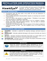
Note 3: For single drive boat, mount on the star-
board side at least 75 mm (3") beyond the swing ra-
dius of the propeller, as shown in the right figure.
Note 4: For twin drive boat, mount between the
drives.
How to install the bracket
1. Cut out the installation template (enclosed with transducer) along the dotted line.
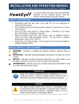
2. At the selected location, position the template, so the arrow at the bottom is
aligned with the bottom edge of the transom. Being sure the template is parallel
to the waterline, tape it in place.
Warning: Always wear safety gog-
gles and a dust mask.
3. Using a 4 mm, #23, or 9/64” bit, drill
three holes 22 mm (7/8”) deep at
the locations indicated. To prevent
drilling too deeply, wrap masking
tape around the bit 22 mm (7/8”)
from the point.
Fiberglass hull: Minimize surface cracking by chamfering the gelcoat. If a cham-
fer bit or countersink bit is not available, start drilling with a 6mm or 1/4” bit to a
depth of 1 mm (1/16”).
4. If you know your transom angle, the bracket is designed for a standard 13° tran-
som angle.
• 11° to 18° angle: No shim is required. Skip to step 3 in "Adjustments".
• Other angles: The shim is required. Skip to step 2 of "Adjustments".
If you do not know the transom angle, temporarily attach the bracket and sensor
to the transom to determine if the plastic shim is needed.
5. Using the three #10 x 1-1/4” self-tapping screws, temporarily screw the bracket to
the hull. DO NOT tighten the screws completely at this time. Follow the step 1-4
Height without
speed sensor
191 mm (7-1/2")
Height with
speed sensor
213 mm (8-1/2")
HeightHeight
75 mm (3")
minimum beyond
swing radius
Align template vertically.
Deadrise angle
Slope of hull
Parallel to
waterline
Align template arrow with
bottom edge of transom.