Page is loading ...

INSTRUCTION MANUAL
COLOR CAMERA
C-CC351A NTSC
C-CC351A PAL
C-CC354A NTSC
C-CC354A PAL
Please follow the instructions in this manual to obtain the optimum results from this unit.
We also recommend that you keep this manual handy for future reference.

TABLE OF CONTENTS
1. SAFETY PRECAUTIONS .............................................................................. 3
2. GENERAL DESCRIPTION ............................................................................ 4
3. PRECAUTIONS ................................................................................................ 4
4. NOMENCLATURE .......................................................................................... 5
5. INSTALLATION ................................................................................................ 6
6. CONNECTIONS ................................................................................................ 6
7. ABOUT THE LENSES
7.1. Lens (optional) Selection and Camera Setting .......................................... 7
7.2. Auto-Iris Lens Installation ............................................................................ 7
8. ADJUSTMENT .................................................................................................. 8
9. CAMERA FUNCTION SETTING .................................................................. 9
Iris Level Setting .................................................................................................. 10
Shutter Speed/Flickering-Reduction Operation Setting ........................................ 11
Wide Dynamic Setting .......................................................................................... 11
Backlight Compensation Setting .......................................................................... 13
Automatic Gain Control (AGC) and Sensitivity Level Settings .............................. 14
White Balance Setting .......................................................................................... 15
Chroma Level Setting ............................................................................................ 17
Enhancement Setting ............................................................................................ 17
Camera ID Title Setting ........................................................................................ 18
Resetting the Camera Functions to the Factory-Preset Values ............................ 19
10. ABOUT THE MODE SWITCH .................................................................... 20
11. SPECIFICATIONS .......................................................................................... 22
2

3
When Installing the Unit
•
Do not expose the unit to rain or an environment
where it may be splashed by water or other liquids,
as doing so may result in fire or electric shock.
•
Install the unit only in a location that can
structurally support the weight of the unit and the
mounting bracket. Doing otherwise may result in
the unit falling down and causing personal injury
and/or property damage.
•
Since the color camera is designed for in-door use,
do not install it outdoors. If installed outdoors, the
aging of parts causes the unit to fall off, resulting in
personal injury. Also, when it gets wet with rain,
there is a danger of electric shock.
When the Unit is in Use
•
Should the following irregularity be found during
use, immediately switch off the power, disconnect
the power supply plug from the AC outlet and
contact your nearest TOA dealer. Make no further
attempt to operate the unit in this condition as this
may cause fire or electric shock.
• If you detect smoke or a strange smell coming
from the unit.
• If water or any metallic object gets into the unit.
• If the unit falls, or the unit case breaks.
• If it is malfunctioning (no image appears).
•
To prevent a fire or electric shock, never open nor
remove the unit case as there are high voltage
components inside the unit. Refer all servicing to
your nearest TOA dealer.
•
Do not insert nor drop metallic objects or
flammable materials in the unit, as this may result
in fire or electric shock.
•
Be sure to inspect the unit periodically for safety
use. Deterioration of the installed part may cause
dropping of the unit, resulting in personal injury
and/or property damage. Contact your TOA dealer
as to the periodical inspection.
When Installing the Unit
•
Avoid installing the unit in humid or dusty locations,
in locations exposed to the direct sunlight, near the
heaters, or in locations generating sooty smoke or
steam as doing otherwise may result in fire or
electric shock.
•
Leave the installation of the unit to your TOA
dealer because the installation requires expert
experience and skills. If the unit falls, this could
cause personal injuries.
•
Do not hang things from the unit as this may cause
the unit to drop, resulting in personal injuries.
1. SAFETY PRECAUTIONS
•
Be sure to read the instructions in this section carefully before use.
•
Make sure to observe the instructions in this manual as the conventions of safety symbols and messages
regarded as very important precautions are included.
•
We also recommend you keep this instruction manual handy for future reference.
Safety Symbol and Message Conventions
Safety symbols and messages described below are used in this manual to prevent bodily injury and property
damage which could result from mishandling. Before operating your product, read this manual first and
understand the safety symbols and messages so you are thoroughly aware of the potential safety hazards.
WARNING
Indicates a potentially hazardous situation which, if mishandled,
could result in death or serious personal injury.
Indicates a potentially hazardous situation which, if mishandled,
could result in moderate or minor personal injury, and/or property
damage.
WARNING
CAUTION
CAUTION

4
2. GENERAL DESCRIPTION
The C-CC351A NTSC is a 1/3 type, NTSC, 120 VAC, high-resolution color camera.
The C-CC351A PAL is a 1/3 type, PAL, 230 VAC, high-resolution color camera.
The C-CC354A NTSC is a 1/3 type, NTSC, 24 VAC or 12 VDC-operated, high-resolution color camera.
The C-CC354A PAL is a 1/3 type, PAL, 24 VAC or 12 VDC-operated, high-resolution color camera.
The 32X electronic sensitivity enhancer and wide dynamic circuitry combine to ensure clear surveillance in
dark locations or in backlit conditions.
3. PRECAUTIONS
•
Do not direct the camera toward the sun or other extremely bright objects.
•
Do not give the camera a great shocks or vibration, as this will damage the camera.
•
It is recommended that the camera be always used in locations where the ambient temperature ranges from
–10°C to
+
50°C and humidity is less than 90%.
•
To clean the camera, use a dry, soft cloth. Never use such volatile liquids as benzine and thinner because
the camera may be discolored or deformed.
•
To clean the camera lens, use an ear syringe or photographic lens tissue to blow or wipe away dust or dirt.
•
Installing the camera cables in close proximity to fluorescent lamps or other electrical appliances can
downgrade the picture quality. In such cases, change the wiring.
•
If there is a strong electric or magnetic field near the camera, such as television transmission antennas,
motors or transformers, this may distort or roll the monitor picture. In such cases, run the entire wiring route
through metal conduit tubing.
•
When operating on 12 VDC, use an external power supply unit with the following ratings:
•
AC adapter or normal power supply unit (with no safety device): Over 12 VDC, 0.5 A
•
Power supply unit with safety device: Over 12 VDC, 2.0 A
Note
This equipment has been tested and found to comply with the limits for a Class A digital device,
pursuant to Part 15 of the FCC Rules. These limits are designed to provide reasonable protection
against harmful interference when the equipment is operated in a commercial environment. This
equipment generates, uses, and can radiate radio frequency energy and, if not installed and used in
accordance with the instruction manual, may cause harmful interference to radio communications.
Operation of this equipment in a residential area is likely to cause harmful interference in which case the
user will be required to correct the interference at his own expense.
Modifications
Any modifications made to this device that are not approved by TOA Corporation may void the authority
granted to the user by the FCC to operate this equipment.
C-CC354A NTSC complies with Part 15 of the FCC Rules.

5
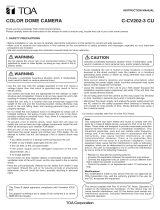
The above numbers are used when describing each part in this manual.
4. NOMENCLATURE
(C-CC351A only)
(C-CC351A) (C-CC354A)
(PAL version)
(PAL version)
(NTSC version)
(NTSC version)
1
2
3
4
5
6
7
8
9
10
11
12
13
11
10
8
6
5
7
5
6
7
Note: Controls , , and are exposed
when you move the cover toward the
rear panel.
(1) Back focal length adjustment ring fixing screw
(2) Back focal length adjustment ring
(3) Lens connector
(4) Menu key
(5) Lens selector switch
(6) Mode switch
(7) Iris control
(8) Vertical phase control
(9) Mount
(10) Video output terminal (BNC)
(11) Power indicator
(12) Power input terminal (24 VAC, 12 VDC)
(13) Power coad
[Left side panel]
[Top panel]
[Right side panel]
[Bottom panel]
[Front panel]
[Rear panel]

6
VIDEO
OUT
VIDEO IN
: BNC plug
Monitor TV
VIDEO
OUT
VIDEO IN
Monitor TV
To AC mains
To 24 VAC or 12 VDC
C-CC354A
C-CC351A
Video output terminal
Video output terminal
10
10
5. INSTALLATION
1. Mount the optional camera mounting bracket to the ceiling or wall. The bracket must be fixed securely
using an electrical box and screws supplied with the bracket. When securing, be sure to run the coaxial
cable through the hole in the bracket.
2. Rotating the bracket's pedestal, fully insert it into the threaded hole in the mount (9).
3. Set the camera's direction, then fix the camera by rotating the lock lever.
Note
The mount can be installed on either the top panel or bottom panel of the camera, and is installed on the
bottom panel by the factory. When changing the position, first remove the mount from the camera and
reattach it to the top panel, then fix it to the mounting bracket.
6. CONNECTIONS
Connect the camera's video output terminal (10) to the monitor, etc.
[Ceiling Mounting Example] [Wall Mounting Example]
Mount
Camera mounting
bracket (optional)
Lock lever
Ceiling surface
Pedestal
Mount
Camera mounting
bracket (optional)
Lock lever
Pedestal
Wall
surface
Wall
surface
Camera mounting
bracket (optional)
9
9

7
7. ABOUT THE LENSES
7.1. Lens (optional) Selection and Camera Setting
•
When using the flickering-reduction function outdoors or under the fluorescent lighting, use the auto-iris lens.
Follow the procedure below to perform the setting:
1. Set the Lens Auto/Manual selector switch of the mode switch (6) to "AUTO" position (factory-preset
position).
2. Set the lens selector switch (5) to "DC" or "VIDEO" position depending on the type of auto-iris lens to use.
Factory-preset for "DC" position.
3. To reduce flickering, set the flickering-reduction switch of the mode switch to "1/100" position
(NTSC.version), "1/120" position (PAL version).
•
When using the flickering-reduction function indoors or in locations where the lighting condition does not
much change, you can use the manual or fixed iris lens by making the following camera settings:
1. Set the Lens Auto/Manual selector switch of the mode switch (6) to "MANU" position. Factory-preset for
"AUTO" position.
2. Set the flickering-reduction switch of the mode switch to "(1/60)" (NTSC version) position,"(1/50)" (PAL
version) position.
Notes
•
When the flickering-reduction switch is set to "1/100" ("1/120") position, the
automatic sensitivity adjustment function cannot be used even if the Lens
Auto/Manual selector switch of the mode switch is set to "MANU" position. Use
the auto-iris lens.
•
To avoid damaging the internal sections of the camera's lens mount, be sure
that the lens flange is less than 5 mm thick as illustrated on the right.
•
C-mount lenses must be used in conjunction with the Lens Mounting Adapter
CF-5 (optional).
7.2. Auto-Iris Lens Installation
1. Attach the lens to the camera.
2. Insert the connector from the lens into the lens
connector (3).
3. Set the Lens Auto/Manual selector switch of the
model switch (6) to "AUTO" position.
4. Set the lens selector switch (5) to DC or VIDEO
position depending on the type of auto-iris lens
to use.
Lens
Under 5 mm
LENS
Lens connector Lens selector switch
Lens selector switch position
1
3
2
4
VIDEO DC
Damping coil
Power +9 V
Video signal
Ground
DC
VIDEO
Damping coil
Driving coil
Driving coil
Lens connector
pin No.
1
2
3
4
3
5
5
–
+
–
+
–
Connector from the lens
Lens connector
3

8
8. ADJUSTMENT
1. Supply power to the camera. The power indicator (11) will light.
2. To view the flickering-free picture, shift the flickering-reduction switch of the mode switch (6) to "1/100"
position (NTSC version) ,"1/120" position (PAL version).
3. Connect the video output terminal (10) to the monitor so that the picture may be displayed on the monitor.
4. Adjust the camera angle viewing the monitor screen.
5. Adjust the lens for the best possible picture reproduction.
•
When using the DC input type lens, adjust the sensitivity with the iris control (7).
•
When using the VIDEO input type lens, adjust the sensitivity with the ALC or LEVEL control of the lens.
Notes
•
Because the iris control is set to the optimum position by the factory, avoid handling it. Rotating the
control more than required could downgrade the image quality or result in camera malfunction. When
readjusting the camera, first set the AGC switch of the mode switch to "OFF" position, then adjust the
iris control for the best possible picture reproduction. After adjustment completion, cover the lens front
with the hand and remove it from the lens a few seconds later. If you find the lens iris is functioning
correctly, shift the AGC switch back to "(AGC)" position.
•
The object that was brought into focus in bright locations could be out of focus in dark conditions. In
such cases, use a commercial ND filter for focus adjustment.
•
When the distance to an object is shorter than the lens' shortest focusing distance or when a zoom lens
is used, if the object is out of focus, adjust the camera as instructed below (back focal length
adjustment):
5-1. Attach a lens to the camera.
5-2. Loosen the back focal length
adjustment ring fixing screw (1).
5-3. Rotating the back focal length
adjustment ring (2), adjust it to the
optimum position.
5-4. Retighten the back focal length
adjustment ring fixing screw.
6. Set the synchronizing method using the synchronization selector switch of the mode switch (6).
One of the following methods can be selected: internal locking (switch position: "INT") and line locking ("LL"
position). When using the line locking method, set the synchronization switch to "LL" position.
Note
You cannot use the line locking method in the area where the power frequency is 50 Hz (NTSC version) ,
60 Hz (PAL version).
7. Using the vertical phase control (8), synchronize the camera. (This adjustment is required only for line
locking mode.) When using multiple line-locked cameras ("LL" position) and switching camera outputs by
means of a sequential switcher, the pictures may be distorted depending on the distance to the power
source or camera installation conditions. In such cases, turn the vertical phase control to avoid the picture
distortion.
Back focal length
adjustment ring
Back focal length
adjustment ring fixing
screw
1
2

9
9. CAMERA FUNCTION SETTING
The following 9 functions can be set and reset.
Note
Be sure to set the mode switch (for AGC, backlight compensation,Wide Dynamic, ATW, and flickering-
reduction operation settings) to the "(MENU)" position. Failure to do this makes it impossible to set the "shutter
speed/flickering-free operation," "backlight compensation," "AGC/sensitivity levels," and "white balance" from
the camera menu. An iris level, chroma level, image quality (enhancement), and camera ID title can be set
from the camera menu regardless of the mode switch setting.
Functions
[1] Iris level
Adjusts the lens iris.
[2] Shutter speed/flickering-reduction operation
NTSC : Sets the shutter speed to Normal (1/60), 1/100 (flickering-reduction), 1/125, 1/250, 1/500,
1/1000, 1/2000, 1/4000, 1/10000 or AES.
PAL : Sets the shutter speed to Normal (1/50), 1/120 (flickering-reduction), 1/125, 1/250, 1/500,
1/1000, 1/2000, 1/4000, 1/10000 or AES.
[3] Wide Dynamic Setting
This function adjusts the image so that an object does not appear too dark or the background too bright, in
order to make both the dark and bright sections of the object visible under backlight conditions.
[4] Backlight compensation
Prevents an object from becoming too dark and the back ground from becoming too bright to be viewed due to
backlight.
[5] Automatic gain control (AGC)/sensitivity levels
An AGC level can be automatically maintained constant, automatically changed or set for OFF. Also, a
sensitivity level can be changed in increments of OFF, 2 times, 4 times, 6 times, 8 times, 10 times, 16 times,
24 times or 32 times.
[6] White balance
Three modes are made available for selection: ATW, AWB, MANUAL
ATW: The camera's white balance varies as an object's color temperature varies.
AWB: The camera operates on the initially-set white balance even if an object's color temperature
changes, once the camera white balance is adjusted when the camera is installed.
MANUAL: To adjust the white balance so that the color looks natural when an object is viewed under a
special light source.
(7) Chroma level
You can adjust the chroma level as you like.
(8) Image quality (enhancement)
You can enhance the contours of an image as you like.
(9) Camera ID title
Up to 8 alphanumeric characters and symbols can be used to set a camera ID title. You can select the ID title
display position from "Lower Right," "Lower Left," "Upper Left," and "Upper Right" of the screen.
Reset
The camera functions can be reset to the factory-preset values (initial setting status). Refer to p. 19.

10
Side panel-mounted menu keys
Note
Use the menu keys ( key, key, SET key, and /CLR key)
located on the camera's side panel to set the camera functions.
Initial screen
1. The camera menu screen appears if the SET key is
pressed for about 2 seconds.
2. Using the key or the key, move the flashing [ ]
cursor to the desired item, and press the SET key to
register the setting. The screen of the selected item
will then be displayed.
3. To exit the camera menu hold down the CLR key for
about 2 seconds.
•
Camera menu display screen
If the item "LENS SELECT" is selected, its screen is
displayed with the iris type automatically set for either
"auto iris" (when the iris selector switch is placed in the
AUTO position) or "manual iris" (when the iris selector
switch is placed in the MANU position) as indicated by
the [ ] cursor.
On the lens selection screen, the [ ] cursor in the
indication of "LOW – – + – – HIGH" is flashing. Set an iris
level by moving the [ ] cursor with the key or key
and press the SET key to register the setting. Pressing
the SET key causes the [ ] cursor in the indication of
"AV – – + – – PK" to flash, permitting its level to be set in
the same manner. When the SET key is pressed for
registration, the display returns to the initial screen.
IRIS LEVEL: LOW (dark), HIGH (bright)
AV (average), PK (peak)
Iris Level Setting

Using the key and the key, move the flashing [ ]
cursor to the desired speed, and press the SET key to
register the setting. The display will then return to the
initial screen.
Notes
•
When "AUTO" (auto iris) is selected on the lens
selection screen, the indication of AES is not
displayed.
•
When "MANUAL" (manual iris) is selected on the lens
selection screen, the shutter speed is set for AES.
11
Shutter Speed/Flickering-Reduction Operation Setting
•
Shutter speed setting screen
NTSC: You can set the shutter speed to NORMAL (1/60), 1/100 (flickering-reduction for), 1/125,
1/250, 1/500, 1/1000, 1/2000, 1/4000, 1/10000 or AES.
PAL : You can set the shutter speed to NORMAL (1/50), 1/120 (flickering-reduction for), 1/125,
1/250, 1/500, 1/1000, 1/2000, 1/4000, 1/10000 or AES.
Wide Dynamic Setting
This function adjusts the image so that an object does not appear too dark or the background too bright, in
order to make both the dark and bright sections of the object visible under backlight conditions.
•
Wide Dynamic Setting Screen
1. Move the cursor [ ] using the and keys to
select OFF, NORMAL or MANUAL.
•
NORMAL: The Wide Dynamic function is enabled
only when a camera detects backlighting.
•
MANUAL: Permits more precise settings to be
made, depending on installation conditions.
Note
When the Backlight Compensation switch is set to
the OFF position, the [ ] cursor is set to OFF.
2. Press the [SET] key to confirm the selection.
•
OFF or NORMAL: The display returns to the initial
screen.
•
MANUAL: The Wide Dynamic Area Setting Screen is displayed. (Refer to p. 12.)

12
•
Wide Dynamic Area Setting Screen
Set the areas on the screen which will be used to
detect backlighting.
When the brightness level of the on-screen area
greatly varies because of a frequently moving object
in the area, its influence can be eliminated by
registering the area as "Invalid." Each of the areas
created by splitting the entire screen into 12
segments, as shown in the figure, can be individually
set as "Valid" or "Invalid."
1. All of Area A flashes. Set the area as "Valid" or
"Invalid" using the or key.
•
To register as "Valid," leave the area in the
condition shown in Figure 1.
•
To register as "Invalid," switch the area to the
condition shown in Figure 2.
2. Press the [SET] key to confirm the setting.
All of Area B flashes.
3. Repeat Steps 1 and 2 above to perform these
settings for all screen areas. After the setting of
Area L is completed, the Wide Dynamic Effect
Setting Screen appears.
•
Wide Dynamic Effect Setting Screen
Set the Wide Dynamic effect depending on the degree
of backlighting.
1. Move the [ ] cursor using the or key to set
the degree of effect.
Set the effect to the [+] position for normal use.
When there are both bright and dark sections on
the screen, moving the cursor toward the [HIGH]
side makes it easier for the Wide Dynamic function
to operate.
Note
If the effect is set too high, the Wide Dynamic
function will continue to work even when no
backlighting is detected, thus decreasing the
contrast.
2. Press the [SET] key to confirm the setting.
The display returns to the initial screen.
Figure 1 : Valid
Figure 2 : Invalid

13
Backlight Compensation Setting
This function prevents an object from becoming too
dark to be viewed due to backlight.
•
Backlight compensation setting screen
Each item represents the size of the screen area used
to detect backlighting.
•
ON 4/4: Whole screen
•
ON 3/4: 3/4 screen (lower screen making up 3/4 of
the whole screen)
•
ON 2/4: 1/2 screen (lower half of the whole screen)
1. Move the [ ] cursor using the or key to
select OFF, "ON 4/4", "ON 3/4", or "ON 2/4".
Note
The [ ] cursor is set to "OFF" when the Backlight Compensation switch is set to OFF or when
"NORMAL" or "MANUAL" is selected on the Wide Dynamic Setting Screen.
2. Press the [SET] key to confirm the selection.
•
When "OFF" is selected, the display returns to the initial screen.
•
When "ON" is selected, the backlight compensation setting screen of the selected size is displayed.
•
Backlight Area Setting Screen
Set the area that detects backlighting on the screen of
the size selected above.
Each area created by splitting the backlight
compensation setting screen into 12 segments can be
individually set as "Valid" or "Invalid," as shown in the
figure. The figure on the right shows an example when
set to "ON 3/4."
1. All of Area A flashes. Set the area as "Valid" or
"Invalid" using the or key.
•
To register as Valid, leave the area in the
condition shown in Figure 1.
•
To register as Invalid, switch the area to the
condition of Figure 2.
2. Press the [SET] key to confirm the setting.
All of Area B flashes.
3. Repeat Steps 1 and 2 above to perform these
settings for all screen areas. After the setting of
Area L is completed, the display returns to the initial
screen.
Figure 2 : Invalid

14
Automatic Gain Control (AGC) and Sensitivity Level Settings
•
AGC/sensitivity level setting screen 1
An AGC level can be automatically changed, maintained constant or set for OFF. This screen also permits a
sensitivity level to be changed in increments of OFF, 2 times, 4 times, 6 times, 8 times, 10 times, 16 times, 24
times or 32 times.
Move the flashing [ ] cursor using the key and the
key to select the desired AGC mode of "AUTO," "FIX"
or "OFF," then press the SET key to register the setting.
When "AUTO" or "OFF" is selected, the AGC/sensitivity
level setting screen 3 is displayed. When "FIX" is
selected, the AGC/sensitivity level setting screen 2 is
displayed.
Note
When the AGC switch is placed in the OFF position,
the mode is set for OFF.
•
AGC/sensitivity level setting screen 2
This screen appears and the [ ] cursor in the AGC level
(dB) indication flashes if "FIX" is selected and the setting
is registered. Vary the level by moving the [ ] cursor
using the key and the key. Pressing the
SET key for registration will advance the display to the
AGC/sensitivity level setting screen 3 "SENS UP."
•
AGC/sensitivity level setting screen 3
Move the flashing [ ] cursor using the key and the
key to select the desired incremental parameter and
press the SET key to register the setting. The display will
then return to the initial screen.
Note
When the AGC switch is placed in the OFF position,
the mode is set for OFF.

15
AGC
Sensitivity Operation
AUTO
AUTO
FIX or OFF
FIX or OFF
Incremental
parameter
OFF
Incremental
parameter
OFF
Automatically adjusts the sensitivity for up to the
designated maximum level. Change the incremental
parameter when giving more consideration to a residual
image reduction than to a sensitivity level increase.
Normally, use this mode.
Use this mode to automatically adjust a AGC level without
using the sensitivity increasing function, and create
pictures free from residual images in poor lighting
conditions.
The AGC level is always maintained at a set level of 0-18
dB, and a sensitivity level automatically increases to up to
the level of the designated incremental parameter as the
lighting condition worsens. Use this function when noise is
a greater annoyance than a residual image.
Handles changes in brightness by means of the lens iris
only. Use this function when noise or residual image is an
annoyance.
White Balance Setting
•
White balance setting screen 1
Three modes are made available for selection: ATW, AWB, MANUAL
ATW: The camera's white balance varies as the object's color temperature varies.
AWB: Once the camera's white balance is adjusted during its installation, the camera operates on
the initially-set white balance even though the object's color temperature changes.
MANUAL: To adjust the white balance so that the color looks natural when an object is viewed under a
special light source.
Move the flashing [ ] cursor with the key and the
key to select the desired mode out of the four modes, then
press the SET key for registration.
When ATW is selected, the [ ] cursor in the indication of
"RED – – + – – BLUE" flashes and the level can be varied
with the key and the key, thereby permitting the
white balance offset to be changed. Pressing the SET key
here for registration will return the display to the initial
screen.
Note
Because the camera readjusts the white balance
depending on a subject, several seconds may be
required till the [ ] cursor begins to flash after ATW has
been selected.
When AWB is selected, Setting Screen 2 (on the next page) is displayed.
When MANUAL is selected, Setting Screen 3 (on the next page) is displayed.
Note
When the ATW switch is placed in the AWB position, the mode is always set for AWB.
Note
The sensitivity increasing function is realized by making longer than usual the time required to store light in
the image sensor. For this reason, if an object becomes dark, a residual image phenomenon take place.

16
When MANUAL is selected, the [ ] cursor in the
indication of "R – – + – – " first flashes, and a red level
can be varied with the key and the key.
If you press the SET key to register the setting, the [ ]
cursor in the indication of "B – – + – – " will then flash,
permitting a blue level to be varied.
When readjusting the red level here, press the CLR key.
The [ ] cursor in the "R – – + – – " indication flashes,
and the red level can be varied again.
Adjust the blue level by using the key and the key,
then press the SET key for registration, and the display
returns to the initial screen.
•
White balance setting screen 3
When AWB is selected, the cursor first flashes at the
position of LAST. If you press the SET key here for
registration, the [ ] cursor in the indication of "RED – –
+ – – BLUE" begins to flash.
If you select "REFRESH" with the key and press the
SET key, the indication of "WAIT" lights for several
seconds, during the period of which the white balance is
readjusted. After readjustment completion, the [ ]
cursor in the indication of "RED – – + – – BLUE" begins
to flash, permitting the white balance to vary as a level is
varied with the key and the key. Pressing the SET
key here for registration will return the display to the initial
screen.
•
White balance setting screen 2

17
Chroma Level Setting
•
Chroma level setting screen 1
You can adjust the chroma level of the picture as you like.
Move the flashing [ ] cursor with the key and the
key to select either NORMAL or MANUAL, then press the
SET key to register the setting.
When you select NORMAL and register its setting, the
display returns to the initial screen. When you select
MANUAL and register its setting, the chroma level setting
screen 2 will be displayed.
•
Chroma level setting screen 2
When you select MANUAL and register its setting, the
[]cursor in the indication of "MIN – – + – – MAX"
flashes, permitting a level to be varied with the key
and the key. Pressing the SET key here for
registration will display to the initial screen.
Enhancement Setting
•
Enhancement setting screen 1
You can enhance the contours of the picture as you like.
Move the flashing [ ] cursor with the key and the
key to select either NORMAL or MANUAL, then press the
SET key to register the setting.
When you select NORMAL and press SET key to register
the setting, the display returns to the initial screen. When
you select MANUAL and press the SET key, the
enhancement setting screen 2 is displayed.

18
Camera ID Title Setting
•
Camera ID title setting screen 1
You can use up to 8 alphanumeric characters and symbols to set a camera ID title. The title can be displayed
at one of the following 4 locations on the screen: lower right, lower left, upper left, and upper right.
Move the flashing [ ] cursor with the key and the
key to select either "ON" (display ON) or "OFF" (display
OFF), then press the SET key to register the setting.
When you select OFF and register its setting, the display
returns to the initial screen without displaying the camera
title. When you select ON and register its setting, the
camera ID setting screen 2 is displayed.
Move the flashing [ ] cursor with the key and the
key to select the title display position from Lower R,
Lower L, Upper L, and Upper R. Press the SET key for
setting the register display the camera ID title setting
screen 3.
•
Camera ID title setting screen 2
•
Enhancement setting screen 2
When you select MANUAL and register its setting, the
[]cursor in the indication of "SOFT – – + – – SHARP"
flashes, permitting a level to be varied with the key
and the key. Pressing the SET key here for
registration will return the display to the initial screen.

19
•
Camera ID title setting screen 3
•
The ID title's leftmost [ ] cursor flashes, indicating
that the character may be entered.
•
The cursor for character selection flashes at the
position of "END". Select the character or symbol by
moving the cursor with the key, key, and
key, and press the SET key to register the setting.
Since the remaining [ ] cursors flash by turns with
each depression of the SET key, set the character for
each [ ] cursor in the same manner.
•
After character entry completion, move the character-
selection cursor to "END" and press the SET key. The
camera ID title is then set, and the display returns to
the initial screen (Refer to p. 3).
•
To change the character entered, move the character-
selection cursor to the position of [ ] or [ ]. Then,
press the SET key to move the ID title cursor to the
desired character position and enter a new character
using the character-selection cursor. After setting
completion, press the SET key. The ID title cursor
moves left or right one character with each depression
of the SET key.
•
To clear all 8 characters simultaneously, move the
character-selection cursor to the position of CLEAR,
then press the SET key.
Resetting the Camera Functions to the Factory-Preset Values
Move the flashing [ ] cursor with the key and the
key to select whether or not to reset to the factory-preset
values, then press the SET key to register the setting.
When you select NO, the display returns to the initial
screen. When you select YES, the current setting is reset
to the factory-preset status, and then the display returns
to the initial screen.
The following table shows the factory-preset values:
[Factory-preset values for the C-CC351A NTSC, C-CC351A PAL, C-CC354A NTSC,C-CC354A PAL]
Setting Item Factory-Preset Value
Shutter speed NORMAL
Wide Dynamic NORMAL
Backlight compensation (BACK LIGHT) OFF
AGC/sensitivity level (AGC/SENS UP) AGC: AUTO, Sensitivity level: X32
White balance ATW
Chroma level NORMAL
Enhancement setting (ENHANCER) NORMAL
Camera ID title (CAMERA ID) OFF

20
•
Lens auto/manual selector switch
AUTO MANU
Set the switch to this position
when using an auto-iris lens.
AUTO MANU
Set the switch to this position
when using a manual-iris or
fixed iris lens.
•
AGC switch
OFF (AGC)
Normally, set the switch to this
position. Even when an ambient
brightness level changes, a video
output level is automatically
maintained constant, providing
the clear picture.
OFF (AGC)
Set this switch to OFF position
when the brightness level of an
object frequently changes.
•
Backlight compensation switch
OFF (BLC)
Normally, set the switch to this
position.
OFF (BLC)
This position prevents an object
from becoming too dark and the
picture background from
becoming too bright to be
viewed.
10. ABOUT THE MODE SWITCH
Set each switch to the position that provides the best picture reproduction. The color camera has the remote
camera control function. When setting the camera's property with the menu key, set the corresponding switch
(AGC, backlight compensation, ATW, and flickering reduction) to the "(MENU)" side (right-hand side).
Lens Auto/Manual selector switch
AGC switch
Backlight compensation switch
ATW switch
Flickering reduction switch
Synchronization switch
(MENU)
AUTO
OFF
OFF
AWB
1/120
INT
MANU
(AGC)
(BLC)
(ATW)
(1/50)
LL
Mode switch
(factory-preset position)
(MENU)
AUTO
OFF
OFF
AWB
1/100
INT
MANU
(AGC)
(BLC)
(ATW)
(1/60)
LL
Mode switch
(factory-preset position)
[PAL]
[NTSC]
•
ATW switch
AWB (ATW)
Normally, set the switch to this
position. This position permits
the camera to automatically
adjust the white balance
depending on the type of light
source (change in color
temperature).
When the ATW function is disabled
because the camera is used under a
special light source or multiple light
sources that differ in color
temperature, set the switch to AWB
position. As soon as the switch is
shifted to this position, the camera
automatically adjusts the white balance of the on-screen
image and thereafter, keeps the white balance status.
Since several seconds are required before the white
balance is set, observe that the object does not change
during that period. When readjusting the white balance, first
shift the switch to "(ATW)" position and shift it back to AWB
position, then adjust the balance in the same manner.
AWB (ATW)
/