Page is loading ...

DO GUIDE
2. Insert the module into the SFP+ cage by doing the following:
a. Verify that the top of the module is visible.
b. With the dust cap facing you, insert the module into the SFP+ cage until the module
latches into place.
3. Remove the dust caps from the LC connectors on one end of the ber-optic cable (patch
cord included with the SFP-10-G-S-U, SFP-10-G-S-D, SFP-10G-S-U-10, and
SFP-10G-S-D-10). Save the dust caps for future use.
NOTE: Depending on the ber-optic cable being used, the cable provides single or dual
LC connectors. The included patch cord provides a single LC connector on one end.
4. Inspect and clean the ber-optic endfaces of the LC connectors.
5. Remove the dust cap from the SFP+ module. Save the dust cap for future use.
SFP-10G Series
10G SFP+ Transceiver Modules
DO Install the Module
An SFP+ (enhanced small form-factor pluggable) transceiver module plugs into the SFP+ cage of a Crestron
®
device.
CAUTION : Observe electrostatic discharge (ESD) precautions when handling SFP+ transceiver
modules. Always wear a wrist strap that connects to an approved grounding source when
installing or coming into contact with the modules.
CAUTION : To prevent damage to an SFP+ module and to any connected cables, disconnect all
cables before installing or removing a module.
NOTE: An SFP+ module is a hot-swappable input/output (I/O) device; therefore, there is no
need to power down a Crestron device when installing or removing a module.
To install an SFP+ module into an SFP+ cage, do the following:
NOTE: Do not remove the dust cap from the SFP+ module until directed to do so in the
following procedure. In addition, always keep the dust caps on the ber-optic cable connectors
until ready to make a connection.
1. Verify that the bail latch is closed.
DO Check the Box
QTY PRODUCT PART NUM.
SFP-10G-S-U and SFP-10G-S-D Only
1 Patch Cord, LC-to-SC 2047106
1 Adapter, SC-to-SC 2047107
SFP-10G-S-U-10 and SFP-10G-S-D-10 Only
10 Patch Cord, LC-to-SC 2047106
10 Adapter, SC-to-SC 2047107
Not Included: Wrist Strap, Antistatic Mat or Foam, Fiber-Optic Endface Cleaning Tools and Inspection Equipment
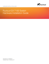
Bail Latch
in Closed Position
Dust Cap
Bail Latch
in Open
Position
RX Optical Bore
TX Optical Bore
Dust Cap
Bail Latch
in Open
Position
TX/RX Optical Bore
SFP+ Module with Dual LC Connectors
SFP+ Module with Single LC Connector
Top of Module Top of Module

DO GUIDE
DOC. 7862A (2046979) 06.16
Specications subject to change without notice.
6. Connect the single LC connector or dual LC connectors of the ber-optic cable to the
appropriate SFP+ module.
7. (SFP-10G-S-U, SFP-10G-S-D, SFP-10G-S-U-10, and SFP-10G-S-D-10 only) Do the
following:
a. Remove a dust cap from one end of the included SC-to-SC adapter. Save the dust
cap for future use.
b. Connect the adapter to the included patch cord.
c. Remove the dust cap from the other end of the adapter. Save the dust cap for future
use.
d. Connect the adapter to the existing CresFiber
®
8G ber-optic cable.
To remove an SFP+ module from an SFP+ cage, do the following:
1. Disconnect the single LC cable connector or dual LC cable connectors from the
SFP+ module.
2. Reinstall the dust cap onto each LC cable connector.
3. (SFP-10G-S-U, SFP-10G-S-D, SFP-10G-S-U-10, and SFP-10G-S-D-10 only) Do the
following:
a. Disconnect the SC-to-SC adapter from the patch cord.
b. Reinstall the dust caps on each end of the adapter and on the SC connectors of the
patch cord.
4. Remove the SFP+ module from the SFP+ cage by doing the following:
a. Open the bail latch by pulling it outward and downward.
b. Grasp the SFP+ module, and then carefully remove the module from the SFP+ cage.
5. Close the bail latch.
6. Reinstall the dust cap into the optical bores of the SFP+ module.
DO Learn More
Visit the website for additional information and the latest rmware updates. To learn
more about this product, use a QR reader application on your mobile device to scan
the QR image.
Crestron Electronics
15 Volvo Drive, Rockleigh, NJ 07647
888.CRESTRON | www.crestron.com
As of the date of manufacture, the product has been tested and found to comply with specications for CE marking.
This product is a Recognized Component to applicable UL Standards and requirements by Underwriters
Laboratories Inc.
Federal Communications Commission (FCC) Compliance Statement
This device complies with part 15 of the FCC Rules. Operation is subject to the following two conditions:
(1) This device may not cause harmful interference, and (2) this device must accept any interference received, including interference
that may cause undesired operation.
CAUTION: Changes or modications not expressly approved by the manufacturer responsible for compliance could void the
user’s authority to operate the equipment.
NOTE: This equipment has been tested and found to comply with the limits for a Class B digital device, pursuant to part 15 of the
FCC Rules. These limits are designed to provide reasonable protection against harmful interference in a residential installation.
This equipment generates, uses and can radiate radio frequency energy and, if not installed and used in accordance with the
instructions, may cause harmful interference to radio communications. However, there is no guarantee that interference will not
occur in a particular installation.
If this equipment does cause harmful interference to radio or television reception, which can be determined by turning the
equipment off and on, the user is encouraged to try to correct the interference by one or more of the following measures:
• Reorient or relocate the receiving antenna.
• Increase the separation between the equipment and receiver.
• Connect the equipment into an outlet on a circuit different from that to which the receiver is connected.
• Consult the dealer or an experienced radio/TV technician for help.
Industry Canada (IC) Compliance Statement
CAN ICES-3(B)/NMB-3(B)
The products are Class 1 laser products. They comply with safety regulations of IEC-60825-1,
FDA 21 CFR 1040 11 and FDA 21 CFR 1040 10.
WARNING: Visible and invisible laser radiation when open. Avoid direct exposure to beam.
NOTE: Plug the included dust cap into the optical transceiver when the ber-optic cable is unplugged.
The specic patents that cover Crestron products are listed at http://www.crestron.com/legal/patents. The product warranty can be found at www.crestron.com/warranty.
Certain Crestron products contain open source software. For specic information, please visit www.crestron.com/opensource.
Crestron, the Crestron logo, and CresFiber are either trademarks or registered trademarks of Crestron Electronics, Inc. in the United States and/or other countries. UL and the UL logo are either
trademarks or registered trademarks of Underwriters Laboratories, Inc. in the United States and/or other countries. Other trademarks, registered trademarks, and trade names may be used
in this document to refer to either the entities claiming the marks and names or their products. Crestron disclaims any proprietary interest in the marks and names of others. Crestron is not
responsible for errors in typography or photography.
This document was written by the Technical Publications department at Crestron.
©2016 Crestron Electronics, Inc.
/