Page is loading ...

Central Heating Cooker
Oil
Instructions for Use,
Installation and Servicing
For use in GB, IE (Great Britain and Eire)
C601972 Issue 4 (December 2007)
IMPORTANT
The front and top of this cooker will become hot whilst in operation. It is therefore recommended that a suitable guard should be
used for the protection of young children, the elderly or infirm.
Please read these instructions carefully before installation or use.
Keep them in a safe place for future reference and when servicing the cooker.
The commissioning sheet found at the end of the User Sections of these instructions should be completed by the installer.
This appliance has been certified for use in countries other than those stated. To install this appliance in these countries, it is essential to obtain the
translated instructions and in some cases the appliance will require modification. Contact Redfyre for further information.

2
CONTENTS
Appliance Commissioning Checklist 3
USER INSTRUCTIONS 4
Cooker Features and Control 5
Oven Cooking Guide 9
Care of the Cooker 10
User Cooker Fault Finding 11
After Sales Service Information 12
INSTALLATION INSTRUCTIONS 13
Technical Specification 13
Site Requirements 14
Oil Supply 15
Site Requirements 22
General 17
Regulations 17
Health and Safety 17
Oil Systems 19
Flue Systems 23
Water Systems 25
Open Systems 26
Electrical Systems 27
CD10 Form 31
SERVICING INSTRUCTIONS 32
Technical Specifications 32
Boiler Flue ways 33
Cooker Flue ways 35
Priming and Adjusting of Pumps 38
Technical Data 39
Nozzle Output 39
Guide to Fault Finding 41
Fault Finding 42
Oil Cooker Burner Spare Parts 43
Cooker Spares 44
C
R E
BOILER SIZE: 6 = 60K Btu 7 = 80K Btu
8 = 100K Btu 9 = 120K Btu
FUEL TYPE 1=NG 5=Oil
COLOUR 00=Cream 02=Blue 03=Black
13=Forest Green 10=Pewter 12=Claret
0
0 00 3

3
FLUE CHECK PASS FAIL
1. Flue is correct for appliance
2. Flue flow test
3. Spillage test
4. Chimney flue draught reading mm wg
OIL CHECK
1. Are all joints and connections airtight?
2. Check KBB operation
3. Check burner operation
4. CD10 and CD11 completed and returned
APPLIANCE COMMISSIONING CHECKLIST
Dealer .....................................................................
...............................................................................
...............................................................................
Contact No. ..............................................................
Date of Purchase .......................................................
Model No. ................................................................
Serial No. .................................................................
Gas Type ..................................................................
Installation Company ................................................
. . . . . . . . . . . . . . . . . . . . . . . . . . . . . . . . . . . . . . . . . . . . . . . . . . . . . . . . . . . . . . . . . . . . . . . . . . . . . . . .
. . . . . . . . . . . . . . . . . . . . . . . . . . . . . . . . . . . . . . . . . . . . . . . . . . . . . . . . . . . . . . . . . . . . . . . . . . . . . . . .
Engineer ...................................................................
Contact No. ...............................................................
OFTEC Reg No. ..........................................................
Date of Installation ....................................................
IMPORTANT NOTICE
Explain the operation of the appliance to the end user, hand the completed instructions to them for safe keeping. The following
information will be required when making any guaranteed claims.
DEALER AND INSTALLER INFORMATION
This product is guaranteed for 2 years from the date of installation, as set out in the terms and conditions of sale between Redfyre and
your local Redfyre dealer. This guarantee will be invalid, to the extent permitted by law, if the above Appliance Commissioning Checklist
is not fully completed by the installer and available for inspection by a Redfyre engineer. The guarantee will only be valid during the
second year, to the extent permitted by law, if the annual service recommended in the Instructions for Use has been completed by an
OFTEC registered engineer, and a copy of the service visit report is available for inspection by a Redfyre engineer.

4
USER INSTRUCTIONS
1. DESCRIPTION
1.1 Congratulations, you are now the proud owner of the new
Redfyre central heating cooker capable of providing full
central heating and domestic hot water. As manufacturers
we are proud of the features and quality of construction of
all our cookers.
2. GENERAL
2.1 As manufacturers and suppliers of cookers and heating
products we take care to ensure these products are designed
and constructed to meet all safety requirements when
properly used and installed. To this end, our products are
thoroughly examined and tested before delivery.
2.2 These Instructions explain the features of your new cooker
and how you can achieve the best results. They describe
cleaning, maintenance, installation and servicing. Please read
these instructions with care so you can enjoy cooking and
can maintain your cooker to give many years of service.
2.3 A qualified installer must install, commission, service or carry
out any remedial work, i.e. electrical fault finding.
2.4 The cooker must not be altered in any way. A cooker that is
incorrectly installed, altered in any way or not serviced can
invalidate approval of the appliance, its warranty and may
affect your statutory rights
2.5 The cooker must be operated by adults; children should not
play with or near the cooker and a suitable guard used for
protection of young children and the infirm.
2.6 Parts of the cooker become very hot when in use (e.g.
hotplates and ovens) and remain hot for a long period after
use. Take great care when using the cooker and use oven
gloves whenever appropriate.
2.7 This Redfyre cooker is designed for cooking, domestic hot
water and central heating and must not be used for other
purposes.
2.8 Make sure you use stable saucepans and always position
handles away from the edge of the hotplate.
2.9 Do not place combustible materials onto the hotplate
surfaces even when the cooker is off.
2.10 Do not spray aerosols in the vicinity of this appliance while it
is operating.
2.11 Do not cover the outlet on the top rear splash back cover.
2.12 Do not allow clothes, furnishings or any combustible
material to come into contact with any flue pipe.
3. RUNNING-IN
3.1 The new surface coating on your Redfyre cooker "burns off"
to create a harmless odour during its first hours of use. This
smell disappears after a short period but if it persists ask your
installer for advice. You should open windows or doors to
keep the room well ventilated until the odour disappears.
4. VENTILATION
4.1 Heat and moisture are produced by oil range cookers.
Ensure the kitchen is well ventilated.
4.2 You may need to open a window or increase mechanical
ventilation during prolonged use of the cooker.
4.3 Air for combustion is taken in through the cooker’s burner
door. DO NOT shut off or block this door or any additional
air vents fitted by your installer in any compartment or to the
outside.
4.4 Any purpose-provided ventilation must be periodically
checked to ensure it is free from obstruction.
5. SERVICING & SPARE PARTS
5.1 The cooker must be serviced every 12 months by a qualified
gas engineer. In all correspondence, always quote the Model
and Serial Number found on the data badge inside the
bottom left door.
5.2 You must turn off your cooker 12 hours before servicing.
Your cooker cannot be serviced while it is hot.
5.3 All Redfyre products must be serviced annually by a
competent person using approved spare parts available from
Redfyre.
6. FROST PROTECTION
6.1 During severe cold weather, if the DHW boiler is out of use
for a lengthy period, we recommend you drain down the
whole system to avoid the risk of freezing, but frequent
draining is not recommended, especially in hard water areas
where this may lead to a build up of scale inside the boiler.
6.2 For short periods of absence, leave the cooker operating at a
low thermostat setting.

5
USER INSTRUCTIONS
COOKER FEATURES AND CONTROLS
The cooker has two ovens to be used as and when you
want: the programmable main oven and the baking oven
beneath. The main oven works like a conventional oven
being controlled by it own thermostat. This thermostat also
controls the rest of the appliance. This oven reaches a
roasting temperature in approximately 20-25 minutes from
cold, or in less time if it has already been in use. The baking
oven works by heat conduction.
Two pressure jet burners give you complete control of the
appliance; one for central heating and one for cooking.
1. MAIN OVEN
1.1 The main oven operates in similar fashion to a conventional
oven, reaching high temperatures in approximately 20-25
minutes from cold. It has its own programmer and a
thermostatic control that also serves the rest of the
appliance.
Position shelves on runners as follows:
1.2 Top Shelf - used to grill meats, vegetables and so on, or
brown dishes such as gratins under heat radiating from the
roof.
1.3 Second Shelf down – used for roasting potatoes, cooking
scones and so on. Covered dishes and hot puddings can be
quickly reheated here.
1.4 Middle Shelf – used for roasting meats, jacket potatoes,
pastry, bread rolls, loaves and pizzas.
1.5 Grid Shelf on oven floor – used for large loaves of bread and
slower roasts (e.g. pork, poultry).
1.6 Direct onto oven floor – for pastry, tarts and pies or crisping
up the bottom of bread loaves. The frying pan can be heated
on the floor before transferring to the hotplates and then
transferred back to the oven floor to finish off. This helps to
keep the area around the hotplate clean and free.
1.7 Spillages inside this oven are automatically burnt off and can
be easily removed with a brush.
2. BAKING OVEN
2.1 This oven operates at approximately 100°C lower than the
main oven. If the main oven is set to 200°C, then the lower
oven is simply used as a warming oven.
2.2 Use the moderate heat of this oven for baking cakes and
biscuits and cooking fish. Slow, long-cooking dishes are often
started on one of the hotplates, then transferred to this oven.
3. HOTPLATE
3.1 The dog bone hotplate is large enough to support seven
various sized saucepans. The heat distribution is graduated
across the hotplate, the left side becoming hottest first. The
higher the oven temperature setting, the hotter the hotplates.
3.2 Two insulated lids conserve heat and should be closed when
the hotplate is not in use.
3.3 When hot, wear gloves to remove the decorative centre
cover.
4. CONTROL PANEL
4.1 One control panel is behind the top left door of the cooker.
1
AR1825
Cooker timer
Cooker
thermostat
Overheat warning
Boiler/oven operating
Boiler thermostat
Reset
It has:
a) a Cooker Timer you must program
b) two Thermostats:
– Boiler Thermostat (controlling the temperature of the
Central Heating water)
– Cooker Thermostat (controlling the temperature of the
oven and other cooking surfaces)
Both the oven and boiler have orange neon indicators that
are lit until the oven or boiler have reached their set
temperature.
c) two Overheat Thermostats you might need to reset.
For safety, there are two manual overheat thermostats for
the oven and boiler inside the top left door. Each overheat
thermostat has a red neon indicator. If these are lit you must
reset each thermostat. The reset buttons spring out if
overheating occurs.
For the oven:
• Pressintheredresetbuttonbeneaththeredindicator
For the boiler:
• Pressinthebrowncross-shapedbuttonbeneaththered
indicator
If frequent resetting is required, contact your distributor;
the appliance may need servicing.
4.2 A further control panel is behind the lower left door. It has:
a) Two Reset buttons: one for the Cooker and one for the
Boiler Burner

6
6. SWITCHING OFF
6.1 If you want to switch off the appliance for short periods:
- For the boiler:
• TurnalltheexternalcontrolstoOFFandturntheboiler
thermostat to OFF
- For the cooker:
• TurnthecookerthermostatandprogrammertoOFF
6.2 To switch off the appliance for longer periods:
• Turnallexternalandinternalcontrolstooffandswitch
off the electricity supply to the appliance.
See the previous section for information on Frost Protection
7. COOKER PROGRAM
You have a choice of either a manual or automatic setting to
turn your boiler ON and OFF.
Make sure the cooker thermostat is demanding heat if
you want the cooker to fire up after setting the program.
Setting the Cooker Timer
7.1 When the appliance is first powered-up you need to remove
the cover protecting the Timer buttons. To start the Timer:
• Pressandholddownthefourbuttonsshowningreyin
the following diagram, 2.
2
AR1624
Re-setting the Time of Day
7.2 Remove the cover protecting the programming buttons
• PressPROGforProgrammingMode
You see a time displayed. The colon dividing hours and
minutes does not flash.
• PressandreleasethePlus(+)orMinus(-)buttononceto
change the time in one minute increments.
Ifyouholddownthe+or-buttonthetimechangesinten
minute increments.
USER INSTRUCTIONS
COOKER FEATURES AND CONTROLS
These buttons are lit if either the cooker or boiler burners
are extinguished by some kind of blockage or restriction.
For either the cooker or boiler:
• Pressthelitbuttontore-firetheburner,ensuringthe
appropriate thermostat is demanding heat
You must contact your distributor if either of these
burners continually needs resetting.
1
AR1826
Boiler burner reset switch
Cooker burner reset switch
Blocked flue reset
Blocked flue light
b) a Blocked Flue Reset Button and red indicator at top
right corner of panel
This light is lit if there is a problem with the flue system. It
can be reset:
• Presstheresetbuttonbesidethelight
If this happens more than twice, call a service engineer to
check the flue for blockages, refer to Section 9.
5. LIGHTING THE BURNERS
Oven Burner
5.1 Lighting the oven burner is a fully automatic process:
• EnsuretheprogrammerisinONmodeandthe
programmer’s neon is lit
• Turntheoventhermostattothedesiredtemperature.
The oven’s orange indicator lights up and remains lit until
the correct temperature is reached.
Boiler Burner
5.2 Lighting the boiler is a fully automatic process:
• MakesureanyexternalcontrolsareONanddemanding
heat
• Turntheboilerthermostattothedesiredtemperature

7
3
AR1625
• PressandreleasethePlus(+)orMinus(-)buttononceto
change the time in one minute increments
• Pressandholdthe+or-buttonthetimechangesinten
minute increments
Factory Settings
7.2 The appliance has 3 pre-settings for each day to
automatically switch the cooker ON and OFF which you can
alter to suit your lifestyle. A morning afternoon and evening
Event is set:
Event 1 ON = 06:30 am OFF = 08:30 am
Event 2 ON = 12:00 pm OFF = 02:00 pm
Event 2 ON = 05:00 pm OFF = 10:30 pm
Adjusting Factory Settings
7.3 To change the factory settings:
• PressPROG
You will see the following display:
4
AR1626
The Event Number is displayed at the top left.
• PressandreleasethePlus(+)orMinus(-)buttononce
to change the time in one minute increments
• Pressandholdthe+or-buttonthetimechangesin
ten minute increments
• PressPROGagaintoselectthetimeatwhichtheboiler
switches OFF for this event
• PressandreleasethePlus(+)orMinus(-)buttononce
to change the time in one minute increments.
5
AR1627
• PressandreleasethePlus(+)orMinus(-)buttononce
to change the time in one minute increments.
• Pressandholdthe+or-buttonthetimechangesin
ten minute increments
The Event number automatically changes after setting each
Event.
7.4 To change the factory settings for Events 2 and 3, repeat the
procedure at 7.3.
• PressPROGagaintoreturntotheRUNmode
•SelectAUTOifyounowanttoruntheprogram
• ReplacethecoverprotectingtheTimerbuttons
Choosing Manual or Automatic Settings
7.5 • UsetheSELECTbuttontochoosebetween:
ON Run continuously
OFF Off continuously
AUTO Follows programme
ALL DAY Turns first programmed event ON
and turns OFF at the end of last
programmed event.
System Overrides
7.6 • UsetheADVor+1HRbuttontochooseanoverride:
ADV Advancesappliancetothenextevent
1HR Adds 1 further hour onto the current event.
7.7 Any Timer settings are retained for 14 days following a
power failure, after which the appliance goes to sleep mode.
If this happens, you must reset the Timer when power is
restored, see 7.1 above.
USER INSTRUCTIONS
COOKER FEATURES AND CONTROLS

8
USER INSTRUCTIONS
COOKER FEATURES AND CONTROLS
8. CENTRAL HEATING
8.1 The heating or hot water are regulated simply by turning the
Boiler thermostat to the temperature you want.
• MakesureyourexternalProgrammerisONandasking
for heat before adjusting the thermostat
1
AR1825
Boiler
thermostat
9. BLOCKED FLUE
9.1 This is a blocked flue sensing device. This is an important
safety device to prevent the products of combustion entering
the room due to a flue problem. Under no circumstances
must this device be put out of operation whilst the cooker is
in use.
9.2 When this device operates it will turn both burners off and
the red neon illuminates. It is not possible to relight the
appliance for approximately 30 minutes after which time the
reset button must be pressed.
9.3 In the event of repeated activation of the blocked flue
device the chimney / flue problem must be investigated and
corrective action taken immediately.
9.4 Access to the reset button is achieved by opening the control
lower left-hand door and pressing the red reset button.

9
USER INSTRUCTIONS
OVEN COOKING GUIDE
2. POULTRY
2.1 Cook Poultry or Game on a trivet in a roasting tin to prevent
the meat stewing in its own juice. Add on time where there
is stuffing.
Setting Shelf Approx Time
Chicken - 170°C 3 20-25minper500g+20-
25 min
Turkey -slow 170°C 3 20-25minper500g+20-
(under 4.5kg) 25 min
-quick 200°C 3 15-20minper500g+15-
20 min
Turkey -slow 170°C 3 30-35minper500g+30-
(over 4.5kg) 35 min
-quick 200°C 3 25-30minper500g+25-
30 min
PorkorVeal -slow 170°C 3 35-40minper500g+35-
40 min
-quick 200°C 3 25-30minper500g+25-
30 min
3. CASSEROLES
3.1 Sear or seal meat over a high heat before adding to a
casserole and bring liquid to boil if required for the
casserole.
Setting Shelf Approx Time
Top Oven 140-150°C 3 Hours according to recipe
Oven-baked Fish 180°C 3 According to size cut,
preparation and recipe
4. CAKES
Setting Shelf Approx Time
Rich Fruit Cake 140-150°C 4 Approximately 45 min per
500g of mixture (7-8") 2-3
hrs
VictoriaSandwich 180°C 3
Queens cakes 180-190°C 2
(2 trays) 3 15-25 min
Scones 200°C 2 10-15 min
5. PASTRIES
Setting Shelf Approx Time
Shortcrust 200°C 4 According to recipe
Flaky 220°C 2 According to recipe
Rough puff 220°C 2 According to recipe
Puff pastry 220°C 2 According to recipe
Heat storage cookers have a reputation for producing very
fine cooking but if you are new to cooking on this type of
stove you need to understand the difference between this
cooker and a conventional cooker. Once the cooker has
reached a desired temperature, there is no quick way of
reducing the heat; you cannot simply turn a knob to lower
the temperature. To keep dishes from boiling over or over-
cooking, you must move your dish from one position on a
hotplate (or in an oven) to another. If you have not used this
type of cooker before you may need to think about your
approach to cooking. This section gives you some typical
examples and guidelines to help you adjust.
From cold, your top right oven should reach a Roasting
Temperature in approximately half an hour.
1. MEAT
1.1 Roast meat cooked inside this type of heat storage cooker
retains its size and shape and rarely needs extra cooking fat.
There are two methods:
• QuickRoastat200
o
C for superior cuts
• SlowRoastat170
o
C for coarser cuts
We recommend searing or sealing an inferior cut at high
temperature for 20/30 minutes before reducing the heat.
You can rest the meat for a few minutes at the end of
cooking by putting it in the lower oven to settle the juices
and allow for easy carving.
1.2 To calculate cooking times, always consider the shape of a
joint as well as its weight. A narrow joint cooks faster than a
solid, even-shaped joint.
1.3 The oven settings and cooking times below are given as a
guide only. Individual tastes may require you to adjust the
settings or reposition the dish being cooked. (If temperatures
seem to vary hugely to those listed, then the oven thermostat
may be faulty and may need replacing.
Note: The tables below are for guidance only. Each cooker
installation varies slightly.
Setting Shelf Approx Time
Beefwith -slow 170°C 3 20-25minper500g+20-
bone 25 min
-quick 200°C 3 15-20minper500g+15-
20 min
Beefboneless -slow 170°C 3 30-35minper500g+30-
35 min
-quick 200°C 3 20-25minper500g+20-
25 min
Lamb -slow 170°C 3 30-35minper500g+30-
35 min
-quick 200°C 3 25-30minper500g+25-
30 min
PorkorVeal -slow 170°C 3 35-40minper500g+35-
40 min
-quick 200°C 3 25-30minper500g+25-
30 min

10
USER INSTRUCTIONS
CARE OF THE COOKER
IMPORTANT:
• Neverusecaustic,citricorabrasivecleanersasthesewill
scratch or damage the surface.
• Alwaystrytowipeupanyspillagesastheyhappen.
• Amoresatisfactoryresultisachievedifthecookeriscool
when cleaning.
• Usehotsoapywaterandaclothfortheenamel,dryingoff
with a soft cloth to avoid streaking.
• Tocleaninsideovens,wirebrushcarbonstainsandvacuum
up deposits. The wire brush scratches the internal oven
surface but this does not damage its natural surface. Ensure
the natural surface is dry after cleaning to prevent oxidation.
Top Plate ¸ ¸
Hot Plate Dome Chrome ¸
Hot Plates ¸ ¸
Oven ¸
Chrome Shelves ¸ ¸ ¸
Oven Door ¸
Door Liner ¸ ¸
Seal ¸
Colour Parts ¸
Front ¸
Sides ¸
Doors ¸
Chrome Handles ¸
Tower Rail ¸
Nylon Brush
CreamCleanerVEApproved
Wire Brush
Hot Water & Soap

11
USER INSTRUCTIONS
COOKER FAULT FINDING
COOKER DOES NOT START
CHECK THE FUSE IN COOKER AND BOILER MAINS SUPPLY HAS NOT
BLOWN
REPLACE FUSE
IF FUSE BLOWS AGAIN CALL
YOUR ENGINEER
IS THE COOKER PROGRAMMER
SWITCHED ON? (NOTE:
PROGRAMMER WILL GO TO SLEEP
IF POWER SUPPLY IS
INTERRUPTED FOR MORE THAN 14
DAYS) - REFER TO PROGRAMMER
INSTRUCTIONS TO WAKE UP THE
PROGRAMMER
CHECK COOKER THERMOSTAT IS SWITCHED ON – AMBER NEON IS LIT
IS THE COOKER RESET NEON LIT?
PRESS RESET BUTTON – (DO NOT RESET MORE THAN TWICE . IF
FAULT PERSISTS CALL YOUR ENGINEER)
No
IS THE COOKER BURNER RESET BUTTON LIT?
PRESS RESET BUTTON - (DO NOT RESET MORE THAN TWICE . IF FAULT
PERSISTS CALL YOUR ENGINEER)
Yes
IF BOTH BOILER & COOKER RESET BUTTONS ARE LIT, IT MAY BE THAT
YOUHAVERUNOUTOFFUEL
Yes
Yes
Yes
No
Yes
Yes
BOILER WILL NOT WORK
IS YOUR EXTERNAL PROGRAMMER CALLING FOR HEAT?
IS THE BOILER BURNER RESET BUTTON LIT?
IS THE COOKER TEMPERATURE NEON LIT WHEN THE COOKER
THERMOSTAT IS TURNED TO MAXIMUM?
SET EXTERNAL PROGRAMMER
IS THE BOILER HIGH LIMIT RESET
NEON LIT ON THE CONTROL
PANEL?
CHECK THE FUSE IN COOKER
BOILER MAINS SUPPLY
REPLACE FUSE.
IF FUSE BLOWS AGAIN CALL
YOUR ENGINEER
PRESS RESET BUTTON. (DO NOT
RESET MORE THAN TWICE. IF
FAULT PERSISTS CALL YOUR
ENGINEER)
IF BOTH BOILER & COOKER RESET
BUTTONS ARE LIT IT MAY BE THAT
YOUHAVERUNOUTOFFUEL
Yes
Yes
Yes
Yes
Yes
No
No
No
No

12
USER INSTRUCTIONS
AFTER SALES SERVICE INFORMATION
1. GUIDE TO REPORTING A FAULT
1.1 A qualified Field Service Engineer is available to attend
breakdown or manufacturing faults whilst this appliance is
under guarantee.
1.2 A charge is made where:
• OurFieldServiceEngineerfindsnofaultwiththe
appliance
• Thecauseofabreakdownisoutsidetheappliance,being
part of the plumbing or heating system, including oil line
or oil deficiency or other equipment not supplied by
Redfyre
• Wheretheappliancefallsoutsidetheguaranteeperiod,
(see Terms and Conditions)
• Theappliancehasnotbeencorrectlyinstalled,
commissioned or serviced as recommended (see
Commissioning, Installation and Servicing Instructions)
• Thebreakdownoccursimmediatelyafteranannual
service visit. In this instance, your appointed Service
Agent must check all his work before requesting Redfyre
to attend
1.3 Over 50% of all service calls are found to have no appliance
fault.
1.4 In the event of an appliance fault or breakdown:
Step 1: Always contact your installer or commissioning
engineer in the first instance. He must thoroughly
check his work before requesting a service visit from
Redfyre.
Step 2: If your appliance has developed an in-guarantee
fault, your installer should contact Redfyre Service
Centre for assistance.
What happens if my installer/engineer is not available?
Step 3: Contact Redfyre Direct. We provide you with the
name and telephone number of our Service Agent.
However, a charge can apply if the fault is not
covered by the appliance guarantee (payment is
requested on site by our independent Service Agent).
Note: Unauthorised invoices for attendance and repair work to this
appliance by any third party are not accepted by Redfyre.
2. THE COOKER ENAMEL
2.1 Every enamelled part of your cooker is unique and has its
own individual characteristics. Coloured parts may differ
slightly in shading. This does not impair performance in any
way and is quite normal.
IMPORTANT CUSTOMER NOTICE
Cosmetic damage, stains and scratches produced by cooking
and cleaning are NOT covered by the statutory guarantee.
The user MUST be aware of this before the cooker is
installed and commissioned.
Refer to the Appliance Commissioning Checklist on page 1
of these Instructions for the product guarantee.

13
Model Cooker 60 80 100 120
Rated input kW 17 18.9 23.8 32.2 39.1
Rated output kW 17.6 21.9 29.3 35.2
Case Emission kW 0.5 0.8 1.0 1.0
Efficiency (NETT) 93% 92% 91% 90%
SAP Rating 88.4% 87.6% 86.2% 85.2%
Efficiency Band B B B C
Burner Minor 1 Minor 1 Minor 1 Minor 4 Minor 8
Oil pump pressure (PSI) 6.8 (100) 6.8 (100) 7.5 (110) 9.5 (140) 7.8 (115)
C0
2
% 11 11 11.5 12 12
Max fuel per hour – kg 1.42 1.58 2.13 2.66 3.2
INSTALLATION INSTRUCTIONS
TECHNICAL SPECIFICATION
1
AR1581
AR1582
Fuel
28 sec kerosene
(BS 28695)
Weight – dry kg 500
Water content – litre 38
Flow and return tappings 2 x 1
1
/
4
" BSP
Test pressure 4.5 bar
Operating pressure 3 bar max
Water side resistance – mbar
10
o
C diff 26
12
o
C diff 8.3
Flue sockets – inside Flue dia.
Dia.145mm 5" (125 mm)
Starting current – Amp 3.5
Running current – Amp 1.2

14
1. COOKER CLEARANCE
1.1 The cooker fits in a 1000mm space with 10mm clearance
each side.
1.2 If the right-hand side of the cooker is to be positioned next
to a wall, an extra 100mm is required at the right-hand side
to remove oven shelves.
1.3 A clearance of 550mm is required above the cooker to raise
the dome lids.
1.4 If a cooker hood is to be fitted, it should be installed to the
manufacturer’s instruction.
1.5 We recommend you allocate 1000mm in front of the cooker
for adequate room to cook and service.
1.6 Where the cooker stands in a recess or against a tiled wall,
under no circumstances must the tiles overlap the black
enamel top plate.
1
AR1583
2. SOUND LEVELS
2.2 While sound levels for this appliance are low, consider the
following before installation:
(a) The flue pipe from the appliance can be cast iron to
reduce noise
(b) Ask the householder if anyone is particularly sensitive to
low noise levels.
(c) Small rooms can amplify noise particularly where the
walls are hollow or tiled.
(d) A chimney passing through a bedroom can sometimes
transmit noise.
INSTALLATION INSTRUCTIONS
SITE REQUIREMENTS
3. HEARTH
3.1 The appliance must be fitted on a non-combustible base.
3.2 The floor must be level and capable of supporting the
installed weight of the appliance and its water content.
4. CONVENTIONAL CHIMNEY
4.1 The chimney should rise as vertically as possible and
terminate at a point not subject to down draughts or wind
eddies. See Flue Systems, Section 5. It should rise 600mm
off the top of the cooker before any bend and have a 3m
effective flue height.
4.2 Brick and masonry chimneys must be lined with a moisture
and acid resistant liner of the same diameter as the boiler
flue outlet.
4.3 A factory made insulated chimney complying with BS 4543
Part 3 may be considered as an alternative to a structural
chimney both for new and existing buildings.
4.4 The use of a flexible stainless steel liner is a convenient
method of lining an existing chimney and this should be
back filled with ‘vermiculite’ or similar insulating material to
retain heat. A flexible liner should also be used in chimneys
fitted with large diameter clay liners to reduce the flue bore
and improve the thermal insulation.
4.5 The use of a draught-stabiliser should not be necessary nor is
it desirable since it allows flue noises to be emitted into the
room. See Flue Systems, Diagram 1.
Notes:
(a) In view of the appliance’s high thermal efficiency it is
important that a liner is fitted, otherwise condensation
problems could result.
(b) Before fitting a liner, the chimney must be thoroughly
cleaned free from all traces of soot and scale.

15
5. OIL SUPPLY
5.1 The burners are factory set to burn 28 sec. Kerosene.
Oil Storage Tanks
5.2 The tank should be large enough to allow for economic
deliveries and be located in the most unobtrusive position,
having regard to the need for safety, filling, maintenance (if
steel tank) and the head of oil required.
5.3 It is highly unlikely that a fire could start from a domestic oil
tank, but the tanks needs to be protected from any fire
originating in a nearby building. The tank should not be
located closer than 1.8 metres from a building, nor closer
than 760mm from a site boundary. Where a tank has to be
less than 1.8 metres, the building wall must not have any
openings other than small ventilation openings. The wall
shall have a half hour resistance to an internal fire and
extend 1.8 metres from any part of the tank.
5.4 Alternatively, a non-combustible radiation barrier must be
provided which meets the requirements of BS 5410 Part 1,
1997. This standard applies to tanks up to a capacity of
3,400 litres which is deemed the maximum size for a single
family dwelling.
Steels Tanks
5.5 Steel tanks should comply with the requirements BS799 Part
5: 1987 and mounted on brick or block piers with a
waterproof membrane between the piers and the tank.
5.6 The tank should be fitted with fill and vent connections
(weather protected), a drain-off cock, shut-off valve and an
oil level indicator.
Plastic Tanks
5.7 Polyethylene tanks are now widely used because of their
advantages over traditional steel tanks:
a) They do no need pier supports and can be mounted
directly on any flat surface giving uniform support for the
tank base.
b) They do not corrode and therefore never need painting.
c) They are easier to handle because of their lower weight.
d) They have a 10 year manufacturer’s guarantee.
5.8 Plastic tanks should be fitted with similar components to
those used with steel tanks.
INSTALLATION INSTRUCTIONS
SITE REQUIREMENTS
6. MAINS ELECTRIC SUPPLY
Note: THIS APPLIANCE MUST BE EARTHED.
6.1 All electrical wiring must be carried out by a qualified
electrician in accordance with current I.E.E. Regulations and
any Local Regulations that may apply. The 230v - 50Hz
electrical supply to the unit and auxiliary controls must be
fused by a double pole switch with a contact separation of at
least 3mm in both poles and shuttered socket (both
complying with the requirements of BS 1363) adjacent to
the boiler.
7. WATER SYSTEMS
7.1 The appliance is suitable for fully pumped open vent &
sealed systems only and the installation must comply with
the requirements of BS 6798 and BS 5449. Fit a drain off
cock in the lowest part of the system. Where the boiler is
also to be used for providing domestic hot water, a double
feed indirect cylinder to BS 1566 Part must be used. Flush
out the system to remove any swarf or residues before fitting
the circulating pump
Note: Where the boiler is installed on a gravity type system
ensure its high efficiency is considered alongside the
gravitational flow. Failure may result in a temperature build-up
within the boiler causing noisy operation.
8. COMBUSTION AIR
8.1 Adequate supply of combustion air is essential for the
efficient and safe operation of the appliance.
8.2 The air opening should be positioned where it causes the
least draught to the house occupants and is not liable to be
accidentally blocked.
8.3 British Standard Code of Practice for Oil Firing BS5410:
Part1 requires a permanent air inlet opening of 550 mm
2
per kW of boiler rated output.
2
AR1650

Model Minimum FREE Area opening "A"
60 166 cm
2
(15 in
2
)
80 198 cm
2
(19.5 in
2
)
100 230 cm
2
(24.5 in
2
)
120 262 cm
2
(30 in
2
)
10. EXTRACTOR FAN
10.1 The combustion performance of the appliance must not be
affected when the kitchen’s extractor fan is running and all
doors and windows are closed. A flue gas check on the CO
2
% and smoke number should be carried out.
16
INSTALLATION INSTRUCTIONS
SITE REQUIREMENTS

17
1. GENERAL
1.1 This appliance has been designed to conform to European
Directive/StandardsBED92/42EECLVDEN60335-1EMC
89/336/EEC
1.2 The Redfyre is supplied suitably equipped for connection to
a conventional chimney.
1.3 The matched pressure jet burners are exceptionally quiet in
operation and ensure clean and efficient combustion with
low NOx emissions.
1.4 The central heating boiler has been designed for use on
open vent or sealed systems. If it is to be used on a sealed
water system up to a maximum working pressure of 3bar,
additional safety devices are required.
1.5 A flow and return socket is provided to facilitate connection
to the heating/hot water system.
1.6 Because of the high efficiency of this range of boilers, it is
recommended they are fitted on a fully pumped system.
1.7 All servicing can be carried out from the front and top of the
appliance. This allows the cooker to be fitted between
kitchen units. The front mounted flue-cover permits easy
access for the removal of the flue baffles and cleaning of
heating surfaces.
1.8 The boiler is fully automatic in operation and incorporates all
the necessary safety controls to ensure safe and reliable
operation.
1.9 The appliance is supplied with the burners set for Kerosene
28 sec. Class C fuel only.
The person(s) who installs this appliance, commissions,
services or carries out any remedial work, i.e. electrical fault
finding, must have suitable engineering qualifications.
2. REGULATIONS
2.1 Installation of the appliance must comply with the following
British Standards and Regulations:
• BS5410LPart1–CodeofPracticeforOilFiring
• BS5449–ForceCirculationHotWaterCentralHeating
Systems
• TheBuildingRegulations
Part ‘J’ (England and Wales)
Part ‘F’ Section 111 (Scotland)
Part ‘L’ (Northern Ireland)
• TheControlofPollution(Oil)Regulations
• CurrentI.E.E.Regulations
• LocalWaterUndertakingsBy-laws
• OFTECInstallationRequirementsforOilFiredBoilersand
Oil Storage Tanks
3. HEALTH & SAFETY AT WORK ACT
3.1 The installer should be aware of his responsibilities under the
Act and provide, where necessary, appropriate protection for
persons carrying out the installation.
3.2 In the interest of safety, the cooker should be installed and
commissioned by a competent engineer, preferably OFTEC
trained and registered.
3.3 A useful guide to Safe Working Practices for Oil Firing
Technicians is published by OFTEC.
Health & Safety
INFORMATION FOR THE INSTALLER AND SERVICE ENGINEERS
3.4 Under the Consumer Protection Act 1987 and the Health &
Safety at Work Act 1974, it is a requirement to provide
information on substances hazardous to health (COSHH
Regulations 1988).
3.5 The Company takes every reasonable care to ensure these
products are designed and constructed to meet these general
safety requirements, when properly used and installed.
3.6 To fulfil this requirement, products are comprehensively
tested and examined before despatch.
3.7 When working on the appliance, it is the Users/Engineers
responsibility to ensure that any necessary personal
protective clothing or equipment is worn appropriate to
parts that could be considered as being hazardous to health
and safety.
3.8 This appliance may contain some of the items below.
INSULATION AND SEALS
3.9 Glass Rope, Mineral Wool, Insulation Pads, Ceramic Fibre,
Glass Insulation:
• Maybeharmfulifinhaled.
• Maybeirritatingtotheskin,eyes,noseorthroat.
• Whenhandling,avoidinhalationandcontactwitheyes.
Use (disposable) gloves, face masks and eye protection.
• Afterhandling,washhandsandotherexposedparts.
• Whendisposing,reducedustwithwatersprayand
ensure parts are securely wrapped.
• FullMaterialSafetyDataSheetsareavailablefromGazco
if required.
GLUES, SEALANTS & PAINT
3.10 Glues, Sealants and Paints are used in the product and
present no known hazards when used in the manner for
which they are intended.
INSTALLATION INSTRUCTIONS

18
KEROSENE & GAS OIL FUELS (MINERAL OILS)
3.11.1 The effect of mineral oils on the skin vary according to the
duration of exposure.
3.11.2 The lighter fractions also remove the protective grease
normally present on the surface of the skin rendering the
skin dry, liable to crack and more prone to damage caused
by cuts and abrasions.
•Avoid,asfaraspossible,anyskincontactwithmineraloil
or with clothing contaminated with mineral oil.
•Donotfiretheburneroutsidethecookeranddonot
breath in mineral oil vapour.
3.11.3 Barrier cream containing lanolin such as Rosalex Antisolv, is
highly recommended together with a strict routine of
personal cleaning.
3.11.4 Under no circumstances should mineral oils be taken
internally.
INSTALLATION INSTRUCTIONS
GENERAL

19
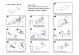
1. OIL SUPPLY LINES
1.1 Flexible oil hoses are supplied with the appliance; filters and
shut-off valves are a requirement. These should be fitted as
illustrated in diagrams 1, 2 and 3.
1.2 The oil shut-off valves should be fitted as close to the burner
as practicable so burners can be disconnected without
undue loss of oil. The filter must be connected in the oil
supply pipe and positioned as close to the oil tank as
possible.
Fire Valve
1.3 A fire valve must be fitted in the oil lines outside the building
with its sensing phial positioned within the cooker casing
below the control panel. A clip is provided for retaining the
phial.
1.4 All oil line joints must be completely sealed and the total
pipe run thoroughly flushed out before connecting to the
burner. No soldered joints are permitted in the oil line.
Single Pipe Oil Line Supply
1.5 When the bottom of the oil supply tank is above the burner,
a single gravity system can be used. The oil supply pipe must
be connected to the suction port on the burner pump via
the flexible hose. See Diagram 1.
Two-Pipe Oil Supply
1.6 Where the bottom of the oil storage tank is below the
burners, a two-pipe system can be fitted.
1.7 When using a two-pipe, it is important that the small Horse
Shoe washer is removed from the BFP 11R3, pumps fitted to
boiler burner, and the by-pass plug is fitted to the cooker
burner. (Refer to oil supply diagram 2).
1.8 An additional Flexible oil line is also required:
Notes:
(1) The pump suction should not exceed -0.4 bar, otherwise
dissolved gas is released from the oil to affect combustion.
(2) The return pipe must end at the same level as the suction
outlet to prevent loss of prime.
(3) The outlet from the tank should be approximately 75mm
above the bottom to prevent sediment and water being
drawn into the supply pipe
Oil De-aerator – Single Pipe Supply
1.9 Where a two-pipe suction lift system is required, but the
return pipe is too long or impractical to run, an oil
de-aerator can be used. Check with the manufacturer’s
specification that the de-aerator being used is suitable for
external use and for two pressure jet burners. The burner is
piped as for a two-pipe system up to the oil de-aerator but
only a single pipe is required to be run back to the oil
storage tank. A non-return valve is not required with this
system, but the by-pass plug must be fitted in the pump as
for a two-pipe system.
2.10 The oil de-aerator should be fitted externally, close to the
cooker and is available from most builders merchants and
some oil tank manufacturers. See Diagram 3.
INSTALLATION INSTRUCTIONS
OIL SYSTEMS

20
1
AR1649
MAXIMUM OIL SUPPLY LENGTH ‘L’
Head ‘H’ Metres 0.5 1.0 1.5 2.0 2.5 3.0 3.5 4.0
Pipe 6mm ID 10 21 31 41 52 62 73 83
Pipe 8mm ID 33 66 98 100 100 100 100 100
Maximum
Length
(Metres)
INSTALLATION INSTRUCTIONS
OIL SYSTEMS
/