Page is loading ...

Motherboard
ROG STRIX
Z390-F
GAMING

ii
E14842
Revised Edition V2
September 2018
Copyright © 2018 ASUSTeK COMPUTER INC. All Rights Reserved.
No part of this manual, including the products and software described in it, may be reproduced,
transmitted, transcribed, stored in a retrieval system, or translated into any language in any form or by any
means, except documentation kept by the purchaser for backup purposes, without the express written
permission of ASUSTeK COMPUTER INC. (“ASUS”).
Product warranty or service will not be extended if: (1) the product is repaired, modied or altered, unless
such repair, modication of alteration is authorized in writing by ASUS; or (2) the serial number of the
product is defaced or missing.
ASUS PROVIDES THIS MANUAL “AS IS” WITHOUT WARRANTY OF ANY KIND, EITHER EXPRESS
OR IMPLIED, INCLUDING BUT NOT LIMITED TO THE IMPLIED WARRANTIES OR CONDITIONS OF
MERCHANTABILITY OR FITNESS FOR A PARTICULAR PURPOSE. IN NO EVENT SHALL ASUS, ITS
DIRECTORS, OFFICERS, EMPLOYEES OR AGENTS BE LIABLE FOR ANY INDIRECT, SPECIAL,
INCIDENTAL, OR CONSEQUENTIAL DAMAGES (INCLUDING DAMAGES FOR LOSS OF PROFITS,
LOSS OF BUSINESS, LOSS OF USE OR DATA, INTERRUPTION OF BUSINESS AND THE LIKE),
EVEN IF ASUS HAS BEEN ADVISED OF THE POSSIBILITY OF SUCH DAMAGES ARISING FROM ANY
DEFECT OR ERROR IN THIS MANUAL OR PRODUCT.
SPECIFICATIONS AND INFORMATION CONTAINED IN THIS MANUAL ARE FURNISHED FOR
INFORMATIONAL USE ONLY, AND ARE SUBJECT TO CHANGE AT ANY TIME WITHOUT NOTICE,
AND SHOULD NOT BE CONSTRUED AS A COMMITMENT BY ASUS. ASUS ASSUMES NO
RESPONSIBILITY OR LIABILITY FOR ANY ERRORS OR INACCURACIES THAT MAY APPEAR IN THIS
MANUAL, INCLUDING THE PRODUCTS AND SOFTWARE DESCRIBED IN IT.
Products and corporate names appearing in this manual may or may not be registered trademarks or
copyrights of their respective companies, and are used only for identication or explanation and to the
owners’ benet, without intent to infringe.
Offer to Provide Source Code of Certain Software
This product contains copyrighted software that is licensed under the General Public License (“GPL”),
under the Lesser General Public License Version (“LGPL”) and/or other Free Open Source Software
Licenses. Such software in this product is distributed without any warranty to the extent permitted by the
applicable law. Copies of these licenses are included in this product.
Where the applicable license entitles you to the source code of such software and/or other additional data,
you may obtain it for a period of three years after our last shipment of the product, either
(1) for free by downloading it from https://www.asus.com/support/
or
(2) for the cost of reproduction and shipment, which is dependent on the preferred carrier and the location
where you want to have it shipped to, by sending a request to:
ASUSTeK Computer Inc.
Legal Compliance Dept.
15 Li Te Rd.,
Beitou, Taipei 112
Taiwan
In your request please provide the name, model number and version, as stated in the About Box of the
product for which you wish to obtain the corresponding source code and your contact details so that we
can coordinate the terms and cost of shipment with you.
The source code will be distributed WITHOUT ANY WARRANTY and licensed under the same license as
the corresponding binary/object code.
This offer is valid to anyone in receipt of this information.
ASUSTeK is eager to duly provide complete source code as required under various Free Open Source
Software licenses. If however you encounter any problems in obtaining the full corresponding source
code we would be much obliged if you give us a notication to the email address [email protected], stating
the product and describing the problem (please DO NOT send large attachments such as source code
archives, etc. to this email address).

iii
Contents
Safety information ...................................................................................................... vi
About this guide ........................................................................................................ vii
ROG STRIX Z390-F GAMING specifications summary ........................................... ix
Package contents ..................................................................................................... xiv
Installation tools and components .......................................................................... xv
Chapter 1: Product Introduction
1.1 Motherboard overview ...............................................................................1-1
1.1.1 Before you proceed ..................................................................... 1-1
1.1.2 Motherboard layout ..................................................................... 1-2
1.1.3 Central Processing Unit (CPU) ................................................... 1-4
1.1.4 System memory .......................................................................... 1-5
1.1.5 Expansion slots ........................................................................... 1-7
1.1.6 Onboard buttons and switches....................................................1-9
1.1.7 Jumpers .................................................................................... 1-10
1.1.8 Onboard LEDs .......................................................................... 1-12
1.1.9 Internal connectors....................................................................1-13
Chapter 2: Basic Installation
2.1 Building your PC system ...........................................................................2-1
2.1.1 CPU installation...........................................................................2-1
2.1.2 Cooling system installation.......................................................... 2-2
2.1.3 Motherboard installation .............................................................. 2-5
2.1.4 DIMM installation......................................................................... 2-6
2.1.5 ATX power connection ................................................................ 2-7
2.1.6 SATA device connection ............................................................. 2-8
2.1.7 Front I/O connector ..................................................................... 2-9
2.1.8 Expansion card installation ....................................................... 2-10
2.1.9 M.2 installation .......................................................................... 2-12
2.1.10 ASUS fan holder installation ..................................................... 2-13
2.2 Motherboard rear and audio connections .............................................2-14
2.2.1 Rear I/O connection .................................................................. 2-14
2.2.2 Audio I/O connections ............................................................... 2-16
2.3 Starting up for the first time ....................................................................2-18
2.4 Turning off the computer ........................................................................2-18

iv
Chapter 3: BIOS Setup
3.1 Knowing BIOS ............................................................................................3-1
3.2 BIOS setup program ..................................................................................3-2
3.2.1 Advanced Mode .......................................................................... 3-3
3.2.2 EZ Mode......................................................................................3-7
3.2.3 Q-Fan Control ............................................................................. 3-8
3.2.4 AI OC Guide .............................................................................. 3-10
3.2.5 EZ Tuning Wizard ..................................................................... 3-11
3.3 My Favorites .............................................................................................3-13
3.4 Main menu ................................................................................................3-15
3.5 Ai Tweaker menu ......................................................................................3-15
3.6 Advanced menu .......................................................................................3-17
3.6.1 Platform Misc Conguration ...................................................... 3-17
3.6.2 CPU Conguration .................................................................... 3-17
3.6.3 System Agent (SA) Conguration ............................................. 3-18
3.6.4 PCH Conguration .................................................................... 3-18
3.6.5 PCH Storage Conguration....................................................... 3-18
3.6.6 PCH-FW Conguration ............................................................. 3-19
3.6.7 Onboard Devices Conguration ................................................ 3-19
3.6.8 APM Conguration .................................................................... 3-20
3.6.9 PCI Subsystem Settings ........................................................... 3-20
3.6.10 USB Conguration .................................................................... 3-20
3.6.11 Network Stack Conguration..................................................... 3-20
3.6.12 NVMe Conguration .................................................................. 3-20
3.6.13 HDD/SSD SMART Information ................................................. 3-20
3.7 Monitor menu ...........................................................................................3-21
3.8 Boot menu ................................................................................................3-21
3.9 Tool menu ................................................................................................. 3-23
3.9.1 ASUS EZ Flash 3 Utility ............................................................ 3-23
3.9.2 ASUS Secure Erase..................................................................3-24
3.9.3 ASUS User Prole..................................................................... 3-25
3.9.4 ASUS SPD Information ............................................................. 3-25
3.9.5 Graphics Card Information ........................................................ 3-25
3.10 Exit menu .................................................................................................. 3-26
3.11 Updating BIOS ..........................................................................................3-27
3.11.1 EZ Update ................................................................................. 3-27
3.11.2 ASUS EZ Flash 3 ...................................................................... 3-28
3.11.3 ASUS CrashFree BIOS 3 .......................................................... 3-30

v
Chapter 4: RAID Support
4.1 RAID configurations ..................................................................................4-1
4.1.1 RAID denitions .......................................................................... 4-1
Appendix
Notices .................................................................................................................... A-1
ASUS contact information ...................................................................................... A-5

vi
Safety information
Electrical safety
• To prevent electrical shock hazard, disconnect the power cable from the electrical outlet
before relocating the system.
• When adding or removing devices to or from the system, ensure that the power cables
for the devices are unplugged before the signal cables are connected. If possible,
disconnect all power cables from the existing system before you add a device.
• Before connecting or removing signal cables from the motherboard, ensure that all
power cables are unplugged.
• Seek professional assistance before using an adapter or extension cord. These devices
could interrupt the grounding circuit.
• Ensure that your power supply is set to the correct voltage in your area. If you are not
sure about the voltage of the electrical outlet you are using, contact your local power
company.
• If the power supply is broken, do not try to x it by yourself. Contact a qualied service
technician or your retailer.
Operation safety
• Before installing the motherboard and adding devices on it, carefully read all the manuals
that came with the package.
• Before using the product, ensure all cables are correctly connected and the power
cables are not damaged. If you detect any damage, contact your dealer immediately.
• To avoid short circuits, keep paper clips, screws, and staples away from connectors,
slots, sockets and circuitry.
• Avoid dust, humidity, and temperature extremes. Do not place the product in any area
where it may become wet.
• Place the product on a stable surface.
• If you encounter technical problems with the product, contact a qualied service
technician or your retailer.
• Your motherboard should only be used in environments with ambient temperatures
between 0°C and 40°C.

vii
About this guide
This user guide contains the information you need when installing and conguring the
motherboard.
How this guide is organized
This guide contains the following parts:
• Chapter1:ProductIntroduction
This chapter describes the features of the motherboard and the new technology it
supports. It includes description of the switches, jumpers, and connectors on the
motherboard.
• Chapter2:BasicInstallation
This chapter lists the hardware setup procedures that you have to perform when
installing system components.
• Chapter3:BIOSSetup
This chapter tells how to change system settings through the BIOS Setup menus.
Detailed descriptions of the BIOS parameters are also provided.
• Chapter4:RAIDSupport
This chapter describes the RAID congurations.
Where to find more information
Refer to the following sources for additional information and for product and software
updates.
1. ASUS website
The ASUS website (www.asus.com) provides updated information on ASUS hardware
and software products.
2. Optional documentation
Your product package may include optional documentation, such as warranty yers,
that may have been added by your dealer. These documents are not part of the
standard package.

viii
Conventions used in this guide
To ensure that you perform certain tasks properly, take note of the following symbols used
throughout this manual.
DANGER/WARNING: Information to prevent injury to yourself when trying to
complete a task.
CAUTION: Information to prevent damage to the components when trying to
complete a task.
IMPORTANT: Instructions that you MUST follow to complete a task.
NOTE: Tips and additional information to help you complete a task.
Typography
Bold text Indicates a menu or an item to select.
Italics
Used to emphasize a word or a phrase.
<Key> Keys enclosed in the less-than and greater-than sign
means that you must press the enclosed key.
Example: <Enter> means that you must press the Enter or
Return key.
<Key1> + <Key2> + <Key3> If you must press two or more keys simultaneously, the key
names are linked with a plus sign (+).

ix
ROG STRIX Z390-F GAMING specifications summary
CPU
Socket 1151 for 9th / 8th Gen Intel® Core™, Pentium® Gold and
Celeron® processors
Supports 14nm CPU
Supports Intel® Turbo Boost Technology 2.0*
* Intel® Turbo Boost Technology 2.0 support depends on the CPU type.
** Refer to www.asus.com for CPU support list.
Chipset Intel® Z390 Chipset
Memory
4 x DIMM, max. 64GB DDR4 4266+(O.C.)* / 4133(OC)* / 4000(OC)*
/ 3866(OC)* / 3733(OC)* / 3600(OC)* / 3466(OC)* / 3400(OC)* /
3333(OC)* / 3300(OC)* / 3200(OC)* / 3000(OC)* / 2800(OC)* /
2666 / 2400 / 2133 MHz, non-ECC, un-buffered memory
Dual channel memory architecture
Supports Intel® Extreme Memory Prole (XMP)
* Hyper DIMM support is subject to the physical characteristics of
individual CPUs. Please refer to Memory QVL(Qualified Vendors List)
for details.
Expansion Slots
Socket 1151 for 9th / 8th Gen Intel® Core™, Pentium® Gold and
Celeron® processors
2 x PCIe 3.0 x16 slots (support x16, x8/x8)
Intel® Z390 Chipset
1 x PCIe 3.0 x16 slot (max. at x4 mode)*
3 x PCIe 3.0 x1 slots
* The PCIe x16_3 slot shares bandwidth with SATA6G_56. The PCIe
x16_3 is set at x2 mode by default.
Graphic
Integrated Graphics Processor - Intel® UHD Graphics support
Multi-VGA output support: HDMI/DisplayPort
- Supports DisplayPort 1.2 with max. resolution 4096 x 2304@60Hz
- Supports HDMI 1.4b with max. resolution 4096 x 2160@30Hz
Multi-GPU Support Supports NVIDIA® 2-Way/Quad-GPU SLI™ Technology
Supports AMD® 3-Way/Quad-GPU CrossFireX™ Technology
(continued on the next page)

x
Storage
Intel® Z390 Chipset with RAID 0, 1, 5, 10, and Intel Rapid
Storage Technology support
- 1 x M.2_1 Socket 3 with M Key, type 2242/2260/2280
(PCIe 3.0 x4 and SATA modes)*
- 1 x M.2_2 Socket 3 with M Key, type 2242/2260/2280/22110
(supports PCIe 3.0 x4 mode)
- 6 x SATA 6Gb/s ports
- Intel® Optane™ Memory Ready
* When the M.2_1(Socket 3) is operating in SATA mode, SATA port 2
(SATA6G_2) will be disabled.
LAN
Intel® I219-V Gigabit LAN- Dual interconnect between the integrated
Media Access Controller (MAC) and physical layer (PHY)
Anti-surge LANGuard
ROG GameFirst V technology
Audio
ROG SupremeFX S1220A 8-Channel High Definition Audio
CODEC
- Supports up to 32-Bit/192kHz playback*
- Impedance sense for front and rear headphone outputs
- High quality 120dB SNR stereo playback output and 113dB SNR
recording input
- SupremeFX Shielding Technology
- Dual OP Ampliers
- Jack-detection, Multi-streaming, and Front Panel Jack-retasking
- Optical S/PDIF out port at back panel
Audio Features:
- Sonic Studio III + Sonic Studio Link
- Sonic Radar III
* Due to limitations in HDA bandwidth, 32-Bit/192kHz is not supported for
8-Channel audio.
USB
Intel® Z390 Chipset
- 1 x USB 3.1 Gen 1 front panel connector
- 4 x USB 3.1 Gen 2 ports (3 Type-A [red] and 1 Type-C [black] at
back panel)
- 4 x USB 3.1 Gen 1 ports (2 ports at back panel [blue], 2 ports at
mid-board)
- 6 x USB 2.0 ports ( 2 ports at back panel [black], 4 ports at
mid-board)
(continued on the next page)
ROG STRIX Z390-F GAMING specifications summary

xi
ROG Exclusive Features
ROG RAMCache III
ROG GameFirst V
ROG CPU-Z
ROG Overwolf
Special Feature
Aura
- Aura Lighting Control
- Aura RGB Strip Headers
- Aura Lighting Effects Synchronization with compatible ASUS ROG
devices
- Aura Addressable Strip Header
ASUS Dual Intelligent Processors 5-Way Optimization by Dual
Intelligent Processors 5
- 5-Way Optimization tuning perfectly consolidates TPU Insight,
EPU Guidance, DIGI+ VRM, Fan Expert 4, and Turbo App
Gamer’s Guardian
- Procool
- SafeSlot
- DIGI+ VRM
- DRAM Overcurrent Protection
- ESD Guards on VGA, LAN, Audio and USB3.1/2.0 ports
- Highly Durable Components
ASUS Exclusive Features
- Armoury crate
- Pre-mounted I/O Shield
- ASUS NODE: hardware control interface
- OptiMem II
- 3D Printing Friendly design
- AI Suite 3
- MemOK! II
- AI Charger
ASUS EZ DIY
- ASUS CrashFree BIOS 3
- ASUS EZ Flash 3
ASUS Q-Design
- Q-LED (CPU, DRAM, VGA, Boot Device LED)
- Q-Slot
- Q-DIMM
(continued on the next page)
ROG STRIX Z390-F GAMING specifications summary

xii
Back I/O Ports
1 x PS/2 keyboard/mouse combo port
1 x HDMI port
1 x DP port
2 x USB2.0 ports
2 x USB 3.1 Gen1 ports [blue]
4 x USB3.1 Gen2 ports (3 x Type-A [red] and 1 x Type-C
ports [black])
1 x Anti-surge LAN (RJ45) port
5 x Audio jacks
1 x Optical S/PDIF out
Internal I/O Ports
1 x USB 3.1 Gen 1 front panel connector
1 x USB 3.1 Gen 1 header supports additional 2 USB 3.1 Gen 1
ports
2 x USB 2.0 header supports additional 4 USB 2.0 ports
6 x SATA 6Gb/s ports
1 x M.2 Socket 3 with M Key, type 2242/2260/2280 storage devices
support (both SATA & PCIe 3.0 x 4 modes)
1 x M.2 Socket 3 with M Key, type 2242/2260/2280/22110 storage
devices support (PCIe 3.0 x 4 mode)
1 x 4-pin CPU FAN connector
1 x 4-pin CPU_OPT fan connector
2 x 4-pin Chassis fan connectors
1 x M.2 FAN connector
1 x 4-pin AIO_PUMP connector
1 x 4-pin W_PUMP+ connector
1 x EXT_FAN header
1 x Thermal sensor connector
1 x 24-pin EATX power connector
1 x 8-pin EATX 12V power connector
2 x Aura RGB headers
1 x Addressable header
1 x MemOK! II switch
1 x Node connector
1 x Clear CMOS jumper (2-pin)
1 x COM port
1 x TPM header
1 x CPU OV header
1 x Front panel audio connector (AAFP)
1 x System panel connector
(continued on the next page)
ROG STRIX Z390-F GAMING specifications summary

xiii
Specications are subject to change without notice. Please refer to the ASUS website for
the latest specications.
ROG STRIX Z390-F GAMING specifications summary
BIOS 1 x 128 Mb Flash ROM, UEFI AMI BIOS, PnP, DMI3.0,
SM BIOS 3.1, ACPI 6.1
Manageability WOL, PXE
Support DVD
Drivers
ASUS Utilities
EZ Update
Anti-virus software (OEM version)
Operating System Support Windows® 10 64-bit
Form Factor ATX Form Factor, 12” x 9.6” (30.5 cm x 24.4 cm)

xiv
Package contents
Check your motherboard package for the following items.
Motherboard 1 x ROG STRIX Z390-F GAMING motherboard
Cables
2 x 2-in-1 SATA 6Gb/s cables
1 x Thermal sensor cable
1 x Extension cable for RGB strips (80cm)
1 x Extension cable for Addressable LED strips (80cm)
Accessories
1 x SLI™ HB Bridge(2-way-M)
1 x ASUS fan holder
1 x M.2 screws package
1 x ROG Strix door hanger
1 x ROG Strix series sticker
1 x Cable ties pack
Application DVD 1 x ROG motherboard support DVD
Documentation 1 x User guide
Others 1 x ROG Strix Thank you card
If any of the above items is damaged or missing, contact your retailer.

xv
Installation tools and components
PC chassis
Power supply unit
Intel® LGA1151 compatible CPU Fan
Intel® LGA1151 CPU
DIMM
SATA hard disk drive
Graphics card (optional)
Phillips (cross) screwdriver
SATA optical disc drive (optional)
1 bag of screws
The tools and components above are not included in the motherboard package.
M.2 SSD module (optional)

xvi

ROG STRIX Z390-F GAMING 1-1
Chapter 1
Product Introduction
1
Chapter 1: Product Introduction
• Unplugthepowercordfromthewallsocketbeforetouchinganycomponent.
• Beforehandlingcomponents,useagroundedwriststraportouchasafelygrounded
objectorametalobject,suchasthepowersupplycase,toavoiddamagingthemdue
tostaticelectricity.
• HoldcomponentsbytheedgestoavoidtouchingtheICsonthem.
• Wheneveryouuninstallanycomponent,placeitonagroundedantistaticpadorinthe
bagthatcamewiththecomponent.
• Beforeyouinstallorremoveanycomponent,ensurethattheATXpowersupplyis
switchedofforthepowercordisdetachedfromthepowersupply.Failuretodoso
maycauseseveredamagetothemotherboard,peripherals,orcomponents.
1.1 Motherboard overview
1.1.1 Before you proceed
Takenoteofthefollowingprecautionsbeforeyouinstallmotherboardcomponentsorchange
anymotherboardsettings.

1-2 Chapter 1: Product Introduction
Chapter 1
Referto1.1.9Internal connectorsand 2.2.1 Rear I/O connectionformoreinformation
aboutrearpanelconnectorsandinternalconnectors.
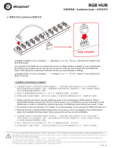
1.1.2 Motherboard layout

ROG STRIX Z390-F GAMING 1-3
Chapter 1
Layout contents
Connectors/Jumpers/Buttons and switches/Slots Page
1. ATXpowerconnectors(24-pinEATXPWR;8-pinEATX12V) 1-19
2. LGA1151CPUSocket 1-4
3. Fanandpumpconnectors(4-pinCPU_FAN;4-pinCPU_OPT;5-pin
EXT_FAN;4-pinW_PUMP+;4-pinAIO_PUMP;4-pinCHA_FAN1-2;4-pin
M.2_FAN)
1-17
4. AURARGBheaders(4-pinRGB_HEADER1-2) 1-22
5. DDR4DIMMslots 1-5
6. MemOK!IIswitch(MemOK!_II) 1-9
7. USB3.1Gen1frontpanelconnector(U31G1_C5) 1-14
8. Intel®Z390SerialATA6Gb/sconnectors(7-pinSATA6G_12;SATA6G_34;
SATA6G_56) 1-13
9. AddressableRGBheader(4-1pinADD_HEADER) 1-23
10. Thermalsensorconnector(2-pinT_SENSOR) 1-16
11. Systempanelconnector(20-3pinPANEL) 1-20
12. ClearRTCRAMjumper(2-pinCLRTC) 1-10
13. USB2.0connectors(10-1pinUSB_E12;USB_1112) 1-16
14. USB3.1Gen1connector(20-1pinU31G1_78) 1-15
15. TPMconnector(14-1pinTPM) 1-18
16. Nodeconnector(12-1pinNODE) 1-18
17. Serialportconnector(10-1pinCOM) 1-24
18. Frontpanelaudioconnector(10-1pinAAFP) 1-14
19. M.2sockets(M.2_1(Socket3);M.2_2(Socket3)) 1-21
20. LEDconnector(8-pinLED1_CON) 1-24
21. CPUOverVoltagejumper(3-pinCPU_OV) 1-11

1-4 Chapter 1: Product Introduction
Chapter 1
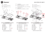
1.1.3 Central Processing Unit (CPU)
ThismotherboardsupportsSocket1151for9th/8thGenIntel®Core™,Pentium®Goldand
Celeron®processors,withmemoryandPCIExpresscontrollersintegratedtosupportdual-
channel(4DIMM)DDR4memoryand16PCIExpress3.0/2.0lanes.
• EnsurethatallpowercablesareunpluggedbeforeinstallingtheCPU.
• Uponpurchaseofthemotherboard,ensurethatthePnPcapisonthesocketand
thesocketcontactsarenotbent.ContactyourretailerimmediatelyifthePnPcap
ismissing,orifyouseeanydamagetothePnPcap/socketcontacts/motherboard
components.ASUSwillshoulderthecostofrepaironlyifthedamageisshipment/
transit-related.
• Keepthecapafterinstallingthemotherboard.ASUSwillprocessReturnMerchandise
Authorization(RMA)requestsonlyifthemotherboardcomeswiththecaponthe
LGA1151socket.
• Theproductwarrantydoesnotcoverdamagetothesocketcontactsresultingfrom
incorrectCPUinstallation/removal,ormisplacement/loss/incorrectremovalofthePnP
cap.
EnsurethatyouinstallthecorrectCPUdesignedforLGA1151socketonly.DONOTinstall
aCPUdesignedforLGA1150,LGA1155,andLGA1156socketsintheLGA1151socket.
/