BARRON QXEDGP Series Thermoplastic Edge-lit Exit Sign Installation guide
- Type
- Installation guide

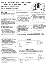
IMPORTANT SAFEGUARDS
READ AND FOLLOW ALL SAFETY INSTRUCTIONS.
When using electrical equipment, basic safety precautions should always be followed including the following:
• DISCONNECT AC POWER SUPPLY BEFORE SERVICING.
• Installation and servicing of this equipment should be performed by qualified service personnel only.
• Ensure that the electrical wiring conforms to the National Electrical Code NEC® and local regulations, if
applicable.
• Do not mount near gas or electrical heaters.
• Do not use outdoors.
• Equipment should be mounted in locations and at heights where it will not be readily subjected to tampering by
unauthorized personnel.
• The use of accessory equipment not recommended by the manufacturer may cause an unsafe condition.
• Any modification or use of non-original components will void the warranty and product liability.
• Do not use this equipment for other than intended use.
• Cap unused wires with enclosed wire nuts or other approved method.
• Make sure wire terminations are secure and leads are properly tucked in appropriate wire channels.
• Use caution when servicing batteries.
• Allow battery to charge for 24 hours before first use.
SAVE THESE INSTRUCTIONS!
Technical Support ■ (623) 580-8943 ■ [email protected]
QXEDGP Series
Installation Instructions
10070253 REV 1 - 09/21 1800-533-3948 www.barronltg.com

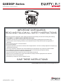
Installation Instructions
Choose mounting configuration (end, top or back mount). Plug remaining holes with the appropriate color plugs.
1. Secure canopy bracket to ceiling or wall.
2. Open the housing cover.
3. Secure housing and canopy with screws (see mounting configuration).
4. Feed the AC input leads (red, black, white) through the housing and canopy’s center hole. Refer to the Wiring
Diagrams section on the 2nd page and make proper electrical connections.
5. Secure canopy into canopy bracket with 1-1/2” long #8-32 screws, then insert battery terminal wire into two-pin male
connector.
6. Connect battery (battery backup model only) only after continuous AC power can
be provided to the unit.
7. Snap housing cover into place.
8. Apply chevron directional indicators as required. Remove application templates
when finished.
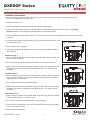
End Mount (Fig. 1)
1. Secure canopy to end plate of fixture using mounting holes C and E with (2) 3/4”
#10-24 screws (included).
2. Run connection wires through large hole between mounting holes C and D.
3. Make electrical connections and mount canopy to junction box (or spider plate if
required) using the two recessed mounting holes and (2) 1-1/2” #8-32 screws
(included).
Top Mount (Fig. 2)
1. Secure canopy to top of fixture using mounting hole A with 3/4“ #8-32 screw and
hex nut, and 1/2” center hole (between mounting holes B and C) with threaded
nipple and hex nuts (included).
2. Run connection wires through threaded nipple.
3. Make electrical connections and mount canopy to junction box (or spider plate if
required) using the two recessed mounting holes and (2) 1-1/2” #8-32 screws
(included).
Back Mount (Fig. 3)
1. Mount canopy to junction box (or spider plate if required) using the two recessed
mounting holes and (2) 1-1/2” #8-32 screws.
2. Run connection wires through large hole in center of canopy.
3. Secure fixture to canopy with (2) 3/4” #10-24 screws (included) by going directly
into mounting holes A and C.
4. Make electrical connections.
Fig. 1 - End Mount
Fig. 2 - Top Mount
Fig. 3 - Back Mount
QXEDGP Series
Installation Instructions
10070253 REV 1 - 09/21 2800-533-3948 www.barronltg.com

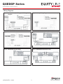
Wiring Diagrams
Fig. 4 - Battery-Backup/Self Diagnostic Wiring
Diagram
Fig. 5 - AC-Only Wiring Diagram
Fig. 6 - Dual Circuit Unit Fig. 7 - 208/220/240 Volt (Battery Backup)
Fig. 8 - 208/220/240 Volt (AC Only) Fig. 9 - 208/220/240 Volt (Dual Circuit)
QXEDGP Series
Installation Instructions
10070253 REV 1 - 09/21 3 800-533-3948 www.barronltg.com

Self-Test/Self-Diagnostics (G2)
Operation
The purpose of this option is to provide Self-testing and Self-diagnostic capabilities to the emergency unit. At
predetermined intervals, the emergency unit will automatically switch into battery mode. Refer to the Self-Test Feature
section below for timing details. The emergency unit will also perform various Self-diagnostic tests to determine if there
are any faults. Visual signaling will alert maintenance personnel to a fault of the emergency unit electronics, battery,
and/or battery charger. The circuitry continuously monitors the operating condition of the emergency unit and battery
charging circuit/battery supply voltage. Refer to the LED Indicator section below for fault reporting details.
Self-Test Feature
• The emergency unit will automatically switch to battery mode every 30 days for a period of 30 seconds.
• The emergency unit will automatically switch to battery mode every 180 days for a period of 30 minutes.
• The emergency unit will automatically switch to battery mode every 365 days for a period of 90 minutes.
LED Indicator
Once the unit is properly installed according to the installation instruction sheet and AC power is supplied, the unit will turn
on and the Self-diagnostic test function will initiate. After this, the bi-color LED will indicate the status of the unit.
• A steady green LED indicates that normal AC power is being supplied to the emergency unit and the battery is
charged.
• A blinking green LED indicates that the unit is in battery mode. Refer to the Test Button Feature section below for
manual test details.
• A red/green flashing LED indicates that the battery is charging.
• A red LED indicates whenever the Self-diagnostic system has detected a fault condition. Refer to the chart below to
determine the fault condition:
Note: A battery recharge failure is more likely seen after a monthly or annual auto-discharge
A battery failure is more likely seen when the unit goes into a monthly/anual discharge test and/or fails to run the
LED strip for the designated amount of time in Test/Emergency mode
Test Button Feature
MANUAL TEST – Pressing the test button will switch the unit into battery mode for a set amount of time. The desired
length of the test is determined by the number of times the test button is pressed.
• Pressing the test button once will switch the unit into battery mode for a period of 30 seconds. The LED indicator will
continuously blink green 1 time during this period.
• Pressing the test button twice within 2 seconds will switch the unit into battery mode for a period of 30 minutes. The
LED indicator will continuously blink green 2 time during this period.
• Pressing the test button 3 times within 2 seconds will switch the unit into battery mode for a period of 90 minutes. The
LED indicator will continuously blink green 3 time during this period.
RESET – Pressing and holding the test button for 3 seconds will cancel a test. Pressing and holding the test button for 6
seconds will reset the LED to a steady green. If multiple faults are present, it may be necessary to repeat this procedure
for each remaining fault indicated by the blinking red LED.
Use in accordance with local building codes.
Red LED Indication
Steady Red
Blinking 1 Time
Blinking 2 Times
Blinking 3 Times
Unit Fault
Battery is Disconnected
Battery Recharge Failure
Battery Failure
LED Failure
Corrective Action
Check Battery Connection
Check Battery Then Consult Factory
Check Battery Then Consult Factory
Check Battery Then Consult Factory
QXEDGP Series
Installation Instructions
10070253 REV 1 - 09/21 4800-533-3948 www.barronltg.com
-
 1
1
-
 2
2
-
 3
3
-
 4
4


BARRON QXEDGP Series Thermoplastic Edge-lit Exit Sign Installation guide
- Type
- Installation guide
Ask a question and I''ll find the answer in the document
Finding information in a document is now easier with AI
Related papers
-
 BARRON NY900U NYC Edge-lit Series Installation guide
-
 BARRON VLEDC Tempo Pro Thermoplastic Series Installation guide
-
 BARRON 700U Series Universal Single or Double-face Steel LED EXIT Sign Installation guide
-
 BARRON NXFX Series NEMA 4X Installation guide
-
 BARRON NXFC Series NEMA 4X Installation guide
-
 BARRON VEX Remote Thermoplastic Series Installation guide
-
 BARRON 400EX Series Die-cast Exit Sign Installation guide
-
 BARRON QMS Series Micro LED Thermoplastic Emergency Unit Installation guide
-
 BARRON NXFE Series NEMA 4X Installation guide
-
 BARRON FRM Series Flush Recessed Emergency Lighting Unit Installation guide