Carrier 23XRV User manual
- Category
- Voice network modules
- Type
- User manual
This manual is also suitable for
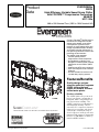
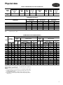
Carrier EVERGREEN 23XRV is a high-efficiency variable speed screw chiller with FOXFIRE™ Compression Technology. It is designed for commercial and industrial applications and can provide cooling and heating. The 23XRV chiller is equipped with a positive displacement screw compressor, which ensures stable operation under all load conditions without the possibility of compressor surge. It also features a variable speed drive, which allows the chiller to adjust its capacity to match the cooling load, resulting in improved efficiency and energy savings.
Carrier EVERGREEN 23XRV is a high-efficiency variable speed screw chiller with FOXFIRE™ Compression Technology. It is designed for commercial and industrial applications and can provide cooling and heating. The 23XRV chiller is equipped with a positive displacement screw compressor, which ensures stable operation under all load conditions without the possibility of compressor surge. It also features a variable speed drive, which allows the chiller to adjust its capacity to match the cooling load, resulting in improved efficiency and energy savings.


-
 1
1
-
 2
2
-
 3
3
-
 4
4
-
 5
5
-
 6
6
-
 7
7
-
 8
8
-
 9
9
-
 10
10
-
 11
11
-
 12
12
-
 13
13
-
 14
14
-
 15
15
-
 16
16
-
 17
17
-
 18
18
-
 19
19
-
 20
20
-
 21
21
-
 22
22
-
 23
23
-
 24
24
-
 25
25
-
 26
26
-
 27
27
-
 28
28
-
 29
29
-
 30
30
-
 31
31
-
 32
32


Carrier 23XRV User manual
- Category
- Voice network modules
- Type
- User manual
- This manual is also suitable for
Carrier EVERGREEN 23XRV is a high-efficiency variable speed screw chiller with FOXFIRE™ Compression Technology. It is designed for commercial and industrial applications and can provide cooling and heating. The 23XRV chiller is equipped with a positive displacement screw compressor, which ensures stable operation under all load conditions without the possibility of compressor surge. It also features a variable speed drive, which allows the chiller to adjust its capacity to match the cooling load, resulting in improved efficiency and energy savings.
Ask a question and I''ll find the answer in the document
Finding information in a document is now easier with AI
Related papers
-
Carrier operating and Start-Up, Operation And Maintenance Instructions Manual
-
-
-
-
-
-
-
-
-
Other documents
-
Makita 6300-4 Datasheet
-
 AquaEuroUSA Mighty Pro Operating instructions
-
Trane Stealth Helical Rotary Model RTAE Quick start guide
-
-
 Shoe Grip BGSG-1 User manual
-
Avanti CF10F0W Owner's manual
-
-
York YST Steam Turbine Centrifugal Chiller User guide
-
Johnson Controls YEWS130 Installation, Operation And Maintanance Instructions
-

