
Installation, Operating, and Maintenance
Instructions
For Use With Positive Pressure Chillers
SAFETY CONSIDERATIONS
Positive pressure storage systems are designed to pro-
vide safe and reliable service when operated within de-
sign specifications. When operating this equipment, use
good judgment and safety precautions to avoid damage
to equipment and property or injury to personnel.
Be sure you understand and follow the procedures and
safety precautions contained in this guide.
DO NOT VENT refrigerant relief valves within a building. Outlet
from rupture disc or relief valve must be vented outdoors in ac-
cordance with the latest edition of ASHRAE 15 (American Society
of Heating, Refrigeration, and Air Conditioning Engineers). The
accumulation of refrigerant in an enclosed space can displace oxy-
gen and cause asphyxiation.
PROVIDE adequate ventilation in accordance with ASHRAE 15,
especially for enclosed and low overhead spaces. Inhalation of high
concentrations of vapor is harmful and may cause heart irregulari-
ties, unconsciousness, or death. Misuse can be fatal.Vapor is heavier
than air and reduces the amount of oxygen available for breathing.
Product causes eye and skin irritation. Decomposition products are
hazardous.
DO NOT USE OXYGEN to purge lines or to pressurize a machine
for any purpose. Oxygen gas reacts violently with oil, grease, and
other common substances.
NEVER EXCEED specified test pressures, VERIFY the allowable
test pressure by checking the instruction literature and the design
pressures on the equipment nameplate.
DO NOT USE air for leak testing. Use only tracer gases and dry
nitrogen.
DO NOT VALVE OFF any safety device.
BE SURE that all pressure relief devices are properly installed and
functioning before operating any machine.
DO NOT WELD OR FLAMECUT any refrigerant line or vessel
until all refrigerant (liquid and vapor) has been removed from chiller.
Traces of vapor should be displaced with dry air or nitrogen and
the work area should be well ventilated. Refrigerant in contact with
an open flame produces toxic gases.
DO NOT USE eyebolts or eyebolt holes to rig machine sections or
the entire assembly.
DO NOT work on high-voltage equipment unless you are a quali-
fied electrician.
DO NOTWORK ON electrical components, including control pan-
els, switches, starters, or oil heater until you are sure ALL POWER
IS OFF and no residual voltage can leak from capacitors or solid-
state components.
LOCK OPENANDTAGelectrical circuits during servicing. IF WORK
IS INTERRUPTED, confirm that all circuits are deenergized be-
fore resuming work.
DO NOT syphon refrigerant by mouth.
AVOID SPILLING liquid refrigerant on skin or getting it into the
eyes. USE SAFETY GOGGLES. Wash any spills from the skin
with soap and water. If any enters the eyes, IMMEDIATELYFLUSH
EYES with water and consult a physician.
NEVER APPLY an open flame or live steam to a refrigerant cyl-
inder. Dangerous overpressure can result. When necessary to heat
refrigerant, use only warm (110 F [43 C]) water.
DO NOT REUSE disposable (nonreturnable) cylinders or
attempt to refill them. It is DANGEROUS AND ILLEGAL. When
cylinder is emptied, evacuate remaining gas pressure, loosen
the collar and unscrew and discard the valve stem. DO NOT
INCINERATE.
CHECK THE REFRIGERANT TYPE before transferring refrig-
erant to the machine. The introduction of the wrong refrigerant can
cause damage or malfunction to this machine.
Operation of this equipment with refrigerants other than those
cited herein should comply withASHRAE 15 (latest edition). Con-
tact Carrier for further information on use of this machine with other
refrigerants.
DO NOTATTEMPTTO REMOVE fittings, covers, etc., while ma-
chine is under pressure or while machine is running. Be sure pres-
sure is at 0 psig (0 kPa) before breaking any refrigerant
connection.
CAREFULLY INSPECT all relief devices, rupture discs, and other
relief devices AT LEAST ONCE A YEAR. If machine operates in
a corrosive atmosphere, inspect the devices at more frequent
intervals.
DO NOT ATTEMPT TO REPAIR OR RECONDITION any relief
device when corrosion or build-up of foreign material (rust, dirt,
scale, etc.) is found within the valve body or mechanism. Replace
the device.
DO NOT install relief devices in series or backwards.
USE CARE when working near or in line with a compressed spring.
Sudden release of the spring can cause it and objects in its path to
act as projectiles.
DO NOT STEP on refrigerant lines. Broken lines can whip about
and cause personal injury and damage to the machine.
DO NOT climb over a machine. Use platform, catwalk, or staging.
Follow safe practices when using ladders.
USE MECHANICAL EQUIPMENT (crane, hoist, etc.) to lift or
move inspection covers or other heavy components. Even if com-
ponents are light, use such equipment when there is a risk of slip-
ping or losing your balance.
BE AWARE that certain automatic start arrangements CAN EN-
GAGE THE STARTER. Open the disconnect ahead of the starter
in addition to shutting off the machine or pump.
USE only repair or replacement parts that meet the code require-
ments of the original equipment.
DOUBLE-CHECK that coupling nut wrenches, dial indicators, or
other items have been removed before rotating any shafts.
DO NOT LOOSEN a packing gland nut before checking that the
nut has a positive thread engagement.
PERIODICALLY INSPECT all valves, fittings, and piping for cor-
rosion, rust, leaks, or damage.
DO NOTMIX REFRIGERANT from chillers that use differentcom-
pressor oils. Compressor damage can result.
19XB
Positive Pressure Storage System
50/60 Hz
Manufacturer reserves the right to discontinue, or change at any time, specifications or designs without notice and without incurring obligations.
Book 2
Tab 5a
PC 211 Catalog No. 531-927 Printed in U.S.A. Form 19XB-1SI Pg 1 6-96 Replaces: New

CONTENTS
Page
SAFETY CONSIDERATIONS ...................1
INTRODUCTION ..............................2
INSTALLATION .............................2-10
Complete Pre-Installation Checks .............2
• IDENTIFY UNIT
• INSPECT SHIPMENT
Mount the Pumpout Unit .....................3
• MOUNTING ON THE CHILLER
• FLOOR MOUNTING
Rig the Storage Tank .........................3
Make Piping Connections ....................7
• INSTALL VENT PIPING TO RELIEF DEVICES
Make Electrical Connections ..................7
CONTROLS AND COMPONENTS ..............11
Pumpout Unit ................................11
• CONTROLS
• SAFETY CONTROL SETTINGS
• COMPRESSOR
• CONDENSER
• OIL SEPARATOR
• SUCTION AND DISCHARGE VALVES
Storage Tank ................................11
• DRAIN VALVE
• DUAL RELIEF VALVES
• PRESSURE GAGE
• LEVEL GAGE
OPERATION ...............................11-15
Overview ...................................11
• REFRIGERANT TRANSFER
• TRANSFERRING LIQUID REFRIGERANT FROM
THE CHILLER COOLER TO THE CHILLER
CONDENSER OR PUMPOUT STORAGE TANK
• TRANSFERRING LIQUID REFRIGERANT FROM
THE CHILLER CONDENSER OR PUMPOUT
STORAGE TANK TO THE CHILLER COOLER
• DISTILLING THE REFRIGERANT
Pumpout and Refrigerant Transfer
Procedures ...............................12
• OPERATING THE PUMPOUT UNIT
• TO READ REFRIGERANT PRESSURES
• POSITIVE PRESSURE CHILLERS WITH STORAGE
TANKS
• CHILLERS WITH ISOLATION VALVES
• DISTILLING THE REFRIGERANT
MAINTENANCE ............................15,16
Pumpout Unit ...............................15
• PUMPOUT COMPRESSOR OIL CHARGE
Storage Tank ...............................16
Ordering Replacement Parts .................16
TROUBLESHOOTING ........................16
INTRODUCTION
The 19XB Positive Pressure Storage (PPS) System has
been designed to help owners and operators of positive pres-
sure chillers store refrigerants HCFC-22 and HFC-134a dur-
ing service and repair work. The 19XB system conserves
these refrigerants and prevents the releaseof excessive amounts
of refrigerant into the atmosphere. The proper use of this
equipment minimizes the loss of HFCs and HCFCs.
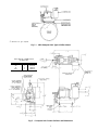
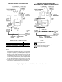
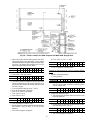
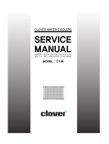
The 19XB PPS system shown in Fig. 1 consists of a pump-
out unit mounted on a storage tank. The pumpout unit is of-
fered as a free-standing unit that can be used with chillers
that have an existing storage tank or with chillers that have
isolation valves that permit built-in refrigerant storage.
The 19XB PPS systems are factory tested and certified to
theAmerican Society of Mechanical Engineers (ASME) pres-
sure vessel code. The tanks are constructed of certified steel
and are pressure rated at 300 psig (2068 kPa). The PPS stor-
age tank is equipped with dual relief valves for proper vent-
ing per ASHRAE 15 (American Society of Heating Refrig-
eration, and Air Conditioning Engineers) guidelines. An
automatic level switch is prewired to the control circuit to
ensure proper storage levels.
The 19EA pumpout unit is a complete, hermetic, compact
unit that consists of:
• a spring-mounted reciprocating compressor with a direct-
drive motor
• a water-cooled refrigerant condenser
• an oil separator
• suction and discharge valves to control refrigerant flow
• prewired safety and control devices.
When referencing refrigerant charges in this manual, the
HCFC-22 charge will be listed first and the HFC-134a value
will follow in brackets.
INSTALLATION
Complete Pre-Installation Checks
IDENTIFY UNIT — Identify the assembly number
(Table 1) printed on the pumpout unit and storage tank name-
plates. Check this information against the job requirements.
Fig. 1 shows the PPS system and its major components.
Refer to Tables 2 and 3 for physical data.
INSPECT SHIPMENT — Inspect unit for damage before
removing unit from shipping conveyance. If unit appears dam-
aged, it should be inspected by a shipping inspector before
removal. File a claim with the shipping company if ship-
ment is damaged or incomplete. The manufacturer is not re-
sponsible for damage incurred during transit.
Check all components. Notify the supplier immediately if
any item is missing. To prevent loss or damage, leave all
parts in their original package until they are needed.
2

Table 1 — Positive Pressure System Assembly Numbers
POSITIVE PRESSURE
SYSTEM ASSEMBLY
NUMBER
PUMPOUT UNIT
ASSEMBLY NO.
REFRIGERANT
COMPRESSOR MOTOR
(V-Ph-Hz)
MAXIMUM
RLA
LRA
STORAGE
TANK
19XB04280205 19EA42-748 R-22 208-3-60 13.2 63.5 28 cu ft
19XB04280206 19EA44-748 R-22 230-3-60 11.5 57.5 28 cu ft
19XB04280207 19EA46-748 R-22 400/460-3-50/60 5.8 28.8 28 cu ft
19XB04280208 19EA47-748 R-22 575-3-60 4.6 23.0 28 cu ft
19XB04280213 19EA48-748 R-134a 208-3-60 13.2 63.5 28 cu ft
19XB04280214 19EA49-748 R-134a 230-3-60 11.5 57.5 28 cu ft
19XB04280215 19EA51-748 R-134a 400/460-3-50/60 5.8 28.8 28 cu ft
19XB04280216 19EA52-748 R-134a 575-3-60 4.6 23.0 28 cu ft
19XB04280601 19EA42-748 R-22 208-3-60 13.2 63.5 None
19XB04280602 19EA44-748 R-22 230-3-60 11.5 57.5 None
19XB04280603 19EA46-748 R-22 400/460-3-50/60 5.8 28.8 None
19XB04280604 19EA47-748 R-22 575-3-60 4.6 23.0 None
19XB04280605 19EA48-658 R-134a 208-3-60 13.2 63.5 None
19XB04280606 19EA49-658 R-134a 230-3-60 11.5 57.5 None
19XB04280607 19EA51-658 R-134a 400/460-3-50/60 5.8 28.8 None
19XB04280608 19EA52-658 R-134a 575-3-60 4.6 23.0 None
19XB04520205 19EA42-748 R-22 208-3-60 13.2 63.5 52 cu ft
19XB04520206 19EA44-748 R-22 230-3-60 11.5 57.5 52 cu ft
19XB04520207 19EA46-748 R-22 400/460-3-50/60 5.8 28.8 52 cu ft
19XB04520208 19EA47-748 R-22 575-3-60 4.6 23.0 52 cu ft
19XB04520213 19EA48-748 R-134a 208-3-60 13.2 63.5 52 cu ft
19XB04520214 19EA49-748 R-134a 230-3-60 11.5 57.5 52 cu ft
19XB04520215 19EA51-748 R-134a 400/460-3-50/60 5.8 28.8 52 cu ft
19XB04520216 19EA52-748 R-134a 575-3-60 4.6 23.0 52 cu ft
LEGEND
LRA — Locked Rotor Amps
RLA — Rated Load Amps
NOTES:
1. Allstoragevessels are300 psig(2068 kPa) designs per the ASME
(American Society of Mechanical Engineers) Boiler Pressure
Vessel Code, Section VIII Division 1.
2. Allunitsaboveareshippedwith a 15psig(103kPa) nitrogen charge.
3. Nominal horsepower for all pumpout units is 3.0.
MountthePumpout Unit— The pumpout unit, if pur-
chased separately, may be mounted directly on the chiller or
it may be floor mounted.
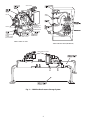
MOUNTING ON THE CHILLER — See instructions pro-
vided with the chiller for mounting the pumpout unit.Atypi-
cal chiller mount is shown in Fig. 2.
FLOOR MOUNTING — Select a ventilated and accessible
area, free of traffic or other hazards. Remove and discard the
4 angle supports at the base of the pumpout unit and bolt the
unit to the floor through the 4
7
⁄
16
in. holes at the base of the
pumpout unit. Special isolation is unnecessary. Contact sur-
face and dimensions for the pumpout unit are given in
Fig. 3.
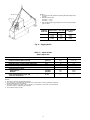
Rig the Storage Tank — The complete 19XB system
can be rigged as a single assembly. See the rigging instruc-
tions on the label attached to the assembly. Also refer to the
rigging guide (Fig. 4), physical data in Tables 2 and 3, and
contact surface and dimensions for the complete system in
Fig. 5. Lift the assembly only from the 4 points indicated in
the rigging guide. Each rigging cable must be capable of
supporting the entire weight of the assembly.
Lifting the assembly from points other than those speci-
fied may result in serious damage to the assembly and
personal injury. Rigging equipment and procedures must
be adequate for assembly. See Tables 2 and 3 for weights.
NOTE: These weights are broken down into pumpout
unit and storage tank weights. For the complete assem-
bly weight, add all components together.
3

CONDENSER
WATER
CONNECTIONS
(FIELD PIPING)
REFRIGERANT
INLET VALVE
VENT VALVE
CONTROL BOX
(WIRING BY
CONTRACTOR)
COMPRESSOR
VALVES
VALVES
19EA PUMPOUT UNIT
19EA CONTROL BOX (INTERIOR)
19EA PUMPOUT UNITS
Fig. 1 — 19XB Positive Pressure Storage System
4

*
3
⁄
8
-16 bolts × 1-in. lg; 4 required.
Fig. 2 — 19EA Pumpout Unit: Typical Chiller Mount
Fig. 3 — Pumpout Unit Contact Surfaces and Dimensions
ELECTRICAL CONNECTION
OPTION LIST
TRADE SIZE QTY LOCATION
1
⁄
2
( 1TOP
3
⁄
4
( 1 BOTTOM
1( 1 MIDDLE
1
1
⁄
4
( 1 MIDDLE
5

Table 2 — Physical Data
19EA Pumpout Unit
ENGLISH (SI)
Pumpout Unit Weight* lb (kg) 210 (95)
Pumpout Condenser Water Flow Rate gpm (L/s) 5 to 7 (.32 to .44)
Pumpout Condenser Water Pressure Drop psig (kPa) 6 to 10.7 (41.4 to 73.8)
Maximum Entering Condenser Water Temperature F (C) 85 (29)
Maximum Leaving Condenser Water Temperature F (C) 100 (37)
Condenser Relief Valve (Fusible Plug) psig (kPa) 385 (2655)
Condenser Pressure Rating
Refrigerant Side psig (kPa) 385 (2655)
Waterside psig (kPa) 150 (1034)
Compressor Rating 1750 rpm (29 r/s) Reciprocating cfm (L/s) 8.7 (.25)
Valves (4-Valve Manifold, Copper with
Brass Turn Knob Valves)
in. OD
1
⁄
2
1
⁄
2
*The pumpout unit weight includes the compressor/condenser, control box, and the oil separator.
NOTES:
1. The motor is hermetic with thermal protection.
2. The control box is mounted and wired with a fuse on/off switch according to NEMA 1 (National
Electrical Manufacturing Association).
3. The starter contactor is located in the control box. The overloads on the motor are wired and the
disconnect switch is supplied by the customer.
4. The condenser tube is copper.
Fig. 4 — Rigging Guide
STORAGE
TANK SIZE
CENTER OF GRAVITY
APPROX. DIM. — ft-in. (mm)
EMPTY WEIGHT
LB (Kg)
AB
28 Ft
3
4- 5
1
⁄
4
(1353)
1-7
7
⁄
8
(505)
2380
(1080)
52 Ft
3
6-10
1
⁄
8
(2086)
1-8
3
⁄
4
(527)
3460
(1569)
NOTES:
1. Each chain must be capable of supporting the entire weight of the
machine.
2. Minimum chain length:
28 ft
3
tank — 108-09
52 ft
3
tank — 158-69
3. Total weight equals empty weight from chart and charge weight
given on label.
6

Table 3 — 19XB Storage Tank Rated Dry Weight and Refrigerant Capacity
English
SIZE CODE
TANK OD
(in.)
DRY WEIGHT*
(lb)
MAXIMUM REFRIGERANT CAPACITY (lb)
ASHRAE/ANSI 15 UL 1963
R-22 R-134a R-22 R-134a
0428 24.00 2380 1842 1860 1704 1716
0452 27.25 3460 3527 3563 3264 3286
SI
SIZE CODE
TANK OD
(mm)
DRY WEIGHT*
(kg)
MAXIMUM REFRIGERANT CAPACITY (kg)
ASHRAE/ANSI 15 UL 1963
R-22 R-134a R-22 R-134a
0428 610 1080 836 844 773 778
0452 592 1569 1600 1616 1481 1491
LEGEND
ANSI — American National Standards Institute
ASHRAE — American Society of Heating, Refrigeration,
and Air Conditioning Engineers
UL — Underwriters’ Laboratories
*The above dry weight includes the pumpout unit weight of 210 lbs (95 kg).
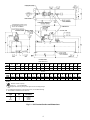
MakePiping Connections— Figure 6 represents typi-
cal pumpout unit/chiller piping connections. Standard con-
nections for
1
⁄
2
-in. OD copper tubing are provided. Install
the field-supplied FPT tee with pipe plug in the piping as
shown in Fig. 6. This tee is used for refrigerant charging.
NOTE: If any field piping runs exceed 50 ft in length, use
7
⁄
8
-in. OD copper tubing to minimize pressure drop.
Pumpout unit water piping connections are shown in
Fig. 6. Both connections are
1
⁄
2
-in. NPT (female). A shutoff
valve should be installed in the water line. Provide a means
for blowing water from the condenser coil at winter shut-
down to prevent freeze-up damage. Refer to the Job Data for
water piping particulars.
INSTALL VENT PIPING TO RELIEF DEVICES — The
pumpout storage tank is factory-equipped with relief de-
vices. Refer to Fig. 5 and Table 2 for size and location of the
relief devices. Vent the relief devices to the outdoors in ac-
cordance with ANSI/ASHRAE 15 Safety Code (latest edi-
tion) for Mechanical Refrigeration and all other applicable
codes. Relief devices are set to relieve at 300 psig
(2068 kPa).
Refrigerant discharged into confined spaces can dis-
place oxygen and cause asphyxiation.
1. If relief devices are manifolded, the cross-sectional area
of the relief pipe must at least equal the sum of the areas
required for individual relief pipes.
2. Provide a pipe plug near outlet side of each relief device
for leak testing. Provide pipe fittings that allow vent pip-
ing to be disconnected periodically for inspection of valve
mechanism.
3. Piping to relief devices must not apply stress to the de-
vice. Adequately support piping. A length of flexible tub-
ing or piping near the device is essential on spring-
isolated machines.
4. Cover the outdoor vent with a rain cap and place a con-
densation drain at the low point in the vent piping to pre-
vent water build-up on the atmospheric side of the relief
device.
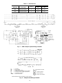
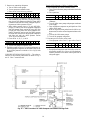
Make Electrical Connections — See nameplate on
compressor of pumpout unit and Table 1 for motor electrical
data. Wire unit according to the diagram inside the control
box.
Fig. 7 is the wiring schematic for a complete system that
includes the 19XB storage tank and the pumpout unit.
Fig. 8 is the wiring schematic for the pumpout unit. Use this
schematic for installations that do not include an auxiliary
pumpout storage tank.
NOTE: Use copper conductors only.
7

DIMENSIONS
ENGLISH (ft-in.)
TANK
SIZE
A B CDE F G H J K LMNPR ST
0428 10- 5 9-10 4-9 2-4
3
⁄
4
1-2
3
⁄
8
3-1
3
⁄
16
4-11 3-8
1
⁄
8
3- 8 2-9
7
⁄
16
3-2 0-3
1
⁄
2
4-8
3
⁄
4
1-7
7
⁄
8
1-7
5
⁄
16
3-7
3
⁄
4
5-0
1
⁄
4
0452 14-11
1
⁄
4
14- 4
1
⁄
2
5-0
7
⁄
8
2-8
1
⁄
2
1-4
1
⁄
4
3-4
7
⁄
16
7- 2
1
⁄
4
4-0 3-11
7
⁄
8
3-1
5
⁄
16
3-5
7
⁄
8
0-3
3
⁄
8
7-1
1
⁄
2
1-8
3
⁄
4
1-7
9
⁄
16
3-8 5-0
1
⁄
2
SI (mm)
TANK
SIZE
ABCDEFGHJKLMNPRST
0428 3175 2997 1448 730 365 945 1499 1121 1118 849 965 89 1442 505 491 1111 1530
0452 4553 4382 1546 826 413 1027 2191 1219 1216 948 1064 86 2172 528 497 1118 1537
NOTES:
1. Denotes center of gravity.
2. Dimensions in ( ) are in millimeters.
3. The weights and center of gravity values given are for an empty storage
tank.
4. For additional information on the pumpout unit, see certified drawings.
5. The available conduit knockout sizes are:
TRADE
SIZE
QTY LOCATION
1
⁄
2
( 1 top
3
⁄
4
( 1 bottom
1( 1 middle
1
1
⁄
4
( 1 middle
Fig. 5 — PPS Contact Surface and Dimensions
8

GENERAL PIPING CONNECTION SIZES
CONNECTION SIZE (in.)
Refrigerant Transfer Connections
1
⁄
2
ODS (female)
Condenser Water Cooling Connectors
1
⁄
2
NPT (female)
Safety Relief Head Pumpdown Condenser
3
⁄
8
Flare (male)
ODS — Outside Diameter, Sweat
LEGEND
Factory-Supplied Tubing
Field-Supplied Tubing
Field-Supplied Tubing (Multiple Chillers)
Service Valve (Factory Supplied)
Service Valve (Field Supplied)
NOTES:
1. The field-supplied tubing is to be
1
⁄
2
-in. OD tubing (min.) and must
be arranged and supported to avoid stresses on the equipment,
transmission of vibrations, and interference with routine access
during the reading, adjusting, and servicing of the equipment. If
the distance from the chiller to the pumpout unit is over 50 ft, then
7
⁄
8
-in. OD tubing (min.) must be used. Provisions should be made
for adjustment in each plane of the tubing and for both periodic
and major servicing of the equipment. Special care must be taken
so that the safety head does not experience tubing strain. Vent
the safety head per ASHRAE 15 (American Society of Heating,
Refrigeration, and Air Conditioning Engineers), latest revision.
2. The tubing and valve from the storage tank to the pumpout com-
pressor is factory supplied when the unit is factory mounted.
Fig.6—Typical Pumpout Unit/Chiller Connection Schematic
CHILLERS WITHOUT ISOLATION VALVES CHILLERS WITH ISOLATION VALVES
(WITH OR WITHOUT PUMPOUT STORAGE TANKS)
9

Table 4 — Relief Devices
STORAGE
TANK SIZE
RELIEF VALVE
OUTLET SIZE
QUANTITY
REQUIRED FACTOR
lb air
min
Kg air
min
28
1 in. NPT
Female Connector
2 31.4 14.2
52
1 in. NPT
Female Connector
2 52.3 23.7
LEGEND
Ground
Field Wiring
Factory Wiring
Contactor Term.
Overload Term.
Pumpdown Term.
Pumpdown Comp’r.
Term.
Fig. 7 — 19XB Pumpout System Wiring Schematic
LEGEND
C—Contactor
Fu — Fuse, 3 Amps
HP — High-Pressure Cutout
L—Compressor Motor Voltage Line (3-phase)
LL — Low-Line Control Voltage (single-phase)
OL — Compressor Overload
T’stat — Internal Thermostat
Compressor Terminal
Contactor Terminal
Overload Terminal
Pumpout Unit Terminal
*Bimetal thermal protector imbedded in motor winding.
Fig. 8 — Pumpout Unit Wiring Schematic
10

CONTROLS AND COMPONENTS
Figure 1 shows the major components of the PPS system.
PumpoutUnit— The pumpout unit consists of a spring-
mounted direct motor-drivenreciprocating compressor,awater-
cooled refrigerant condenser, an oil separator, suction and
dischargevalves to control refrigerant flow, and prewired safety
and control devices. The pumpout unit comes equipped with
a 4-way transfer valve manifold to interconnect both liquid
and vapor transfer and to pressurize the chiller during trans-
fer of refrigerant from chiller to storage tank.
CONTROLS — The pumpout unit has the following con-
trols: an on/off switch, a 3-amp fuse, compressor overloads,
an internal thermostat, a compressor contactor, and a refrig-
erant high pressure cutout.
SAFETYCONTROL SETTINGS — The pumpout unit high-
pressure switch (Fig. 1) is set to open at the settings listed
in Table 5. The switch setting is checked by operating the
pumpout condenser and slowly throttling the pumpout con-
denser water.
Table 5 — High Condition Pressure Switch Settings
English
REFRIGERANT
HIGH-PRESSURE SWITCH
Cutout CutIn
R-134a 161 ± 5 psig
+0
130 − 5 psig
R-22 220 ± 5 psig
+0
185 − 5 psig
SI
REFRIGERANT
HIGH-PRESSURE SWITCH
Cutout Cut-In
R-134a 1110±34kPa
+0
896 − 34 kPa
R-22 1517 ± 34 kPa
+0
1276 − 34 kPa
NOTES:
1. R-22 units use high-pressure cutout switch HK01UA181.
2. R-134a units use high-pressure cutout switch HK01UA187.
COMPRESSOR — The pumpout compressor assembly has
a positive displacement of 1750 rpm (29 r/s) and 8.7 cfm
(0.004 m
3
/s). It comes equipped with thermal protection on
the motor and an in-line oil separator.
CONDENSER — The water-cooled condenser is fully ASME
constructed. During transfer, it condenses refrigerant vapor
to liquid. The condenser transfer tank safety relief valves com-
ply with ASHRAE 15 standards.
OIL SEPARATOR — The pumpout unit includes an in-line
oil separator to remove oil that becomes mixed with refrig-
erant and returns the oil to the compressor.
SUCTION AND DISCHARGE VALVES — The pumpout
unit comes with a 4-way transfer valve manifold to inter-
connect both liquid and vapor transfer and to pressurize the
chiller during transfer of refrigerant from chiller to storage
tank or from one chiller vessel to another.
Storage Tank — The storage tank is rated for positive
pressure refrigerants underASME Section VIII pressure ves-
sel codes with a minimum of 300 psig (2068 kPa) rating.
The tank components include:
DRAIN VALVE — Located at its lowest point of drain with
a minimum of 1 in. NPT.
DUAL RELIEF VALVES — Two relief valves and a 3-way
shut-off valve.
PRESSURE GAGE —A30 in.-0-400 psig (101-0-2760 kPa)
compound pressure gage.
LEVEL GAGE — Liquid level gage (magnetically coupled
dial type) with electronic shut-off at 90% liquid capacity.
During transfer of refrigerant into and out of the pump-
out storage tank, carefully monitor the storage tank level
gage. Do not fill the tank more than 90% of capacity to
allow for refrigerant expansion. Overfilling may result
in damage to the tank and personal injury. For maxi-
mum refrigerant capacity, refer to Table 2.
OPERATION
Overview —
Transferring refrigerant from one vessel to
another is accomplished by using either gravity or pressure
differential. A difference in elevation between 2 vessels re-
sults in a gravity flow of liquid; a difference in pressure forces
the liquid from one vessel to the other. The latter method
requires lowering the pressure in one vessel. If there is liq-
uid in that vessel, its temperature must be lowered, and the
pressure in the other vessel must be simultaneously
increased.
Under most circumstances, creating the pressure differ-
ential is not a difficult process. Some applications, such as
ice storage, outdoor installations, or installations with high
temperature differentials between the storage tank and the
chiller may require additional consideration. In some in-
stances, it may be necessary to add auxiliary heat to one of
the vessels or to insulate the storage tank at job sites where
high ambient temperature or sun load make it difficult to re-
duce the temperature and pressure in the tank. Outdoor in-
stallations must have a roof or cover over the storage tank to
ensure that the pressure in the tank does not exceed the chiller
relief pressure setting.
REFRIGERANT TRANSFER — When refrigerant is being
evacuated from the chiller cooler or condenser vessels, any
liquid refrigerant left in a vessel will flash off, lowering the
temperature in that vessel enough to freeze the fluid (usually
water) flowing through the cooler or condenser tubes. This
event, called tube freeze-up, can cause extensive damage to
the chiller; therefore, all liquid refrigerant must be removed
from a vessel before evacuation of refrigerant vapor is started.
If all the liquid cannot be removed, then the cooler water
and condenser water pumps must be operated throughout the
process of evacuating refrigerant vapor to keep fluid moving
through the cooler and condenser tubes.
TRANSFERRING LIQUID REFRIGERANT FROM THE
CHILLER COOLER TO THE CHILLER CONDENSER OR
PUMPOUT STORAGE TANK — Chiller and pumpout unit
valves are set to permit the pumpout compressor to dis-
charge refrigerant vapor into the cooler vessel, lowering pres-
sure in the condenser vessel/storage tank. The pressure dif-
ferential forces liquid from the cooler vessel into the condenser
vessel/storage tank. After all the liquid is transferred, the re-
frigerant vapor remaining in the cooler vessel can be drawn
off by reducing pressure in the chiller and discharging the
vapor through the pumpout unit condenser into the con-
denser vessel/storage tank.
TRANSFERRING LIQUID REFRIGERANT FROM THE
CHILLER CONDENSER OR PUMPOUT STORAGE TANK
TO THE CHILLER COOLER — Chiller and pumpout unit
valves are set to increase pressure in the chiller condenser
vessel/storage tank and to reduce pressure in the cooler ves-
sel. Pressure in the cooler vessel is lowered to correspond to
a saturated refrigerant liquid temperature 2 F (1.1 C) above
the freezing temperature of the liquid circulating through the
chiller cooler/condenser tubes (34 F [1.1 C] for water). The
valves are set so that the pressure in the cooler vessel is lower
than that of the condenser vessel/storage tank, forcing the
liquid into the cooler vessel.
11

NOTE: During this operation, maintain water circulation
through the chiller cooler and condenser vessels to prevent
tube freeze-up.
DISTILLING THE REFRIGERANT — Refrigerant vapor
is transferred from the chiller cooler vessel or pumpout stor-
age tank through the pumpout condenser, condensed to a liq-
uid, and pumped to the chiller condenser vessel. During this
operation, water circulation must be maintained in the pump-
out condenser. Refrigerant impurities left in the chiller cooler
vessel or storage tank are then drained off. This operation
can take from 4 to 14 hours, depending on the type and amount
of refrigerant being distilled.
The Pumpout and Refrigerant Transfer Procedures sec-
tion gives step-by-step instructions on performing these
operations.
Pumpout and Refrigerant Transfer Procedures
—
Three possibilities are available:
1. If there are no isolation valves on the chiller, a complete
pumpout system with a pumpout storage tank and pump-
out unit is needed.
2. Whether or not isolation valves are available on the chiller,
the refrigerant can be pumped to and isolated in a pump-
out storage tank by using the pumpout unit.
3. If isolation valves are available on the chiller, the refrig-
erant can be pumped to either the cooler vessel or the
condenser vessel using the pumpout unit.
The following procedures describe how to transfer refrig-
erant from one vessel to another and how to evacuate the
chiller.
Do not mix refrigerants from chillers that use different
compressor oils. Compressor damage can result. For ex-
ample, the compressor oil in a 23XL chiller that uses
HCFC-22 refrigerant can cause severe lubrication prob-
lems in a 19XL chiller that uses HCFC-22 refrigerant.
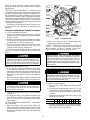
OPERATING THE PUMPOUT UNIT
1. Be sure that the suction and the discharge service valves
on the pumpout compressor (Fig. 9) are open (back-
seated) during operation. Rotate the valve stem fully coun-
terclockwise to open. Frontseating the valve closes the
refrigerant line and opens the gage port to compressor
pressure.
2. Make sure that the pumpout compressor holddown bolts
(Fig. 2) have been loosened to allow free spring travel.
Transfer, addition, or removal of refrigerant in spring-
isolated chillers may place severe stress on external pip-
ing if springs on the chiller have not been blocked in
both up and down directions.
3. Open the refrigerant inlet valve (Fig. 9) on the pumpout
compressor.
4. Oil should be visible in the pumpout compressor sight
glass under all operating conditions and during shut-
down. If oil is low, add oil as described in the Mainte-
nance section.
TO READ REFRIGERANT PRESSURES — During pump-
out or leak testing:
1. Refer to the display on the chiller control center to de-
termine refrigerant-side pressures and low (soft) vacuum.
Use a quality vacuum indicator or manometer to measure
evacuation and dehydration and to ensure the desired range
and accuracy.
2. Attach a 30 in.-0-400 psi (101-0-2760 kPa) gage to the
storage tank to determine its pressure.
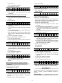
POSITIVE PRESSURE CHILLERS WITH STORAGE
TANKS — In the Valve/Condition tables that accompany
these instructions, the letter 9C9 indicates a closed valve.
Figures 9 and 10 show the locations of the valves.
Always run chiller cooler and condenser water pumps
and always charge or transfer refrigerant as a gas when
chiller vessel pressure is less than 60 psig (414 kPa)
[30 psig (207 kPa)]. Below these pressures, liquid re-
frigerant flashes into gas, resulting in extremely low tem-
peratures in thecooler/condensertubes and possibly causing
tube freeze-up.
Transfer Refrigerant from Pumpout Storage Tank to Chiller:
During transfer of refrigerant into and out of the 19XB
storage tank, carefully monitor the storage tank level gage.
Do not fill the tank more than 90% of capacity to allow
for refrigerant expansion. Overfilling may result in dam-
age to the tank and personal injury.
1. Equalize refrigerant pressure.
a. Turn on chiller water pumps and monitor chiller
pressures.
b. Close pumpout and storage tank valves 2, 4, 5, 8, and
10, and close refrigerant charging valve 7; open chiller
isolation valve 11 and any other chiller isolation valves,
if present.
c. Open pumpout and storage tank valves 3 and 6; open
chiller valves 1a and 1b.
VALVE 1a1b23456781011
CONDITION C C C C C C
d. Gradually crack open valve 5 to increase chiller pres-
sure to 60 psig (414 kPa), [ 30 psig (207 kPa)]. Slowly
feed refrigerant to prevent freeze-up.
OIL RETURN
LINE
CONNECTION
CONDENSER
WATER
CONNECTIONS
REFRIGERANT
INLET VALVE
VENT VALVE 8
PUMPOUT
CONTROL BOX
(WIRING BY
CONTRACTOR)
Fig. 9 — Pumpout Unit
12

e. Open valve 5 fully after the chiller pressure rises above
the freezing point of the refrigerant. Let the storage
tank and chiller pressure equalize. Open refrigerant charg-
ing valve 7 and storage tank charging valve 10 to let
liquid refrigerant drain into the chiller.
VALVE 1a1b23456781011
CONDITION C C C
2. Transfer remaining refrigerant.
a. Close valve 5 and open valve 4.
VALVE 1a1b23456781011
CONDITION C C C
b. Turn off the pumpout condenser water, and turn on the
pumpout compressor to push liquid refrigerant out of
the storage tank. Monitor the storage tank level until
the tank is empty.
c. Close refrigerant charging valves 7 and 10.
d. Turn off the pumpout compressor.
e. Turn off the chiller water pumps.
f. Close valves 3 and 4.
g. Open valves 2 and 5.
VALVE 1a1b23456781011
CONDITION C C C C C
h. Turn on pumpout condenser water.
i. Run the pumpout compressor until the storage tank pres-
sure reaches 5 psig (34 kPa), 18 in. Hg (41 kPa
absolute).
j. Turn off the pumpout compressor.
k. Close valves 1a, 1b, 2, 5, and 6.
VALVE 1a1b23456781011
CONDITION C C CCCCCCCC
l. Turn off pumpout condenser water.
Transfer the Refrigerant from Chiller to Pumpout Storage
Tank.
1. Equalize refrigerant pressure.
a. Valve positions:
VALVE 1a1b23456781011
CONDITION C C C C C C
b. Slowly open valve 5 and refrigerant charging valves 7
and 10 to allow liquid refrigerant to drain by gravity
into the storage tank.
VALVE 1a1b23456781011
CONDITION C C C
2. Transfer the remaining liquid.
a. Turn off pumpout condenser water. Place valves in the
following positions:
VALVE 1a1b23456781011
CONDITION C C C
b. Run the pumpout compressor for approximately 30 min-
utes, then close valve 7 and 10.
VALVE 1a1b23456781011
CONDITION C C C C C
c. Turn off the pumpout compressor.
Fig. 10 — Valve Locations for 19XB Pumpout Unit With 19XB Storage Tank
13

3. Remove any remaining refrigerant.
a. Turn on chiller water pumps.
b. Turn on pumpout condenser water.
c. Place valves in the following positions:
VALVE 1a1b23456781011
CONDITION C C C C C
d. Run the pumpout compressor until the chiller pres-
sure reaches 60 psig (414 kPa), [30 psig (207 kPa)];
then, shut off the pumpout compressor. Warm chiller
condenser water will boil off any entrapped liquid re-
frigerant and chiller pressure will rise.
e. When chiller pressure rises to 70 psig (483 kPa),
[40 psig (276 kPa)]; turn on the pumpout compressor
until the pressure again reaches 60 psig (414 kPa)
[30 psig (207 kPa)]; then, turn off the pumpout com-
pressor. Repeat this process until the chiller pressure
no longer rises; then, turn on the pumpout compressor
and pump out until the chiller pressure reaches
18 in. Hg (41 kPa absolute).
f. Close valves 1a, 1b, 3, 4, and 6.
VALVE 1a1b23456781011
CONDITION C C CCCCCCCC
g. Turn off the pumpout condenser water.
4. Establish vacuum for service. To conserve refrigerant, op-
erate the pumpout compressor as described in Step 3e un-
til the chiller pressure is reduced to 18 in. Hg (41 kPa
absolute).
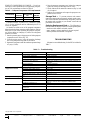
CHILLERS WITH ISOLATION VALVES — The valves re-
ferred to in the following instructions are shown in Fig. 9
and 11. Valve 7 remains closed.
Transfer All Refrigerant to Chiller Condenser Vessel:
1. Push refrigerant into chiller condenser vessel.
a. Turn on the chiller water pumps and monitor the chiller
pressure.
b. Valve positions:
VALVE 1a1b2345811
CONDITION C C C
c. Equalize the refrigerant in the chiller cooler and
condenser.
d. Turn off chiller water pumps and pumpout condenser
water supply.
e. Turn on pumpout compressor to push liquid out of the
chiller cooler vessel.
f. When all liquid has been pushed into the chiller con-
denser vessel, close the cooler refrigerant isolation valve
(11).
g. Turn on the chiller water pumps.
h. Turn off the pumpout compressor.
2. Evacuate gas from chiller cooler vessel.
a. Close pumpout valves 2 and 5; open valves 3 and 4.
VALVE 1a1b2345811
CONDITION C C C C
b. Turn on pumpout condenser water.
c. Run pumpout compressor until the chiller cooler ves-
sel pressure reaches 18 in. Hg vac (41 kPa absolute).
Monitor pressures on the chiller control panel and on
refrigerant gages.
Fig. 11 — Valve Locations for 19XB Pumpout Unit Without Storage Tank
14

d. Close valve 1a.
e. Turn off pumpout compressor.
f. Close valves 1b, 3, and 4.
VALVE 1a1b2345811
CONDITION C C CCCCCC
g. Turn off pumpout condenser water.
h. Turn off chiller water pumps and lock out chiller
compressor.
Transfer All Refrigerant to Chiller Cooler Vessel:
1. Push refrigerant into the chiller cooler vessel.
a. Turn on the chiller water pumps and monitor the chiller
pressure.
b. Valve positions:
VALVE 1a1b2345811
CONDITION C C C
c. Equalize the refrigerant in the chiller cooler and
condenser.
d. Turn off chiller water pumps and pumpout condenser
water.
e. Turn on pumpout compressor to push refrigerant out
of the chiller condenser.
f. When all liquid is out of the chiller condenser, close
valve 11 and any other liquid isolation valves on the
chiller.
g. Turn off the pumpout compressor.
2. Evacuate gas from chiller condenser vessel.
a. Turn on chiller water pumps.
b. Make sure that pumpout valves 3 and 4 are closed and
valves 2 and 5 are open.
VALVE 1a1b2345811
CONDITION C C C C
c. Turn on pumpout condenser water.
d. Run the pumpout compressor until the chiller con-
denser reaches 18 in. Hg (41 kPa absolute). Monitor
pressure at the chiller control panel andrefrigerant gages.
e. Close valve 1b.
f. Turn off pumpout compressor.
g. Close valves 1a, 2, and 5.
VALVE 1a1b2345811
CONDITION C C CCCCCC
h. Turn off pumpout condenser water.
i. Turn off chiller water pumps and lock out chiller com-
pressor.
Return Refrigerant to Normal Operating Conditions
1. Be sure that the chiller vessel that was opened has been
evacuated.
2. Turn on chiller water pumps.
3. Open valves 1a, 1b, and 3.
VALVE 1a 1b 2 3 4 5 8 11
CONDITION C C C C C
4. Crack open valve 5, gradually increasing pressure in the
evacuated chiller vessel to 60 psig (414 kPa), [30 psig
(207 kPa)]. Feed refrigerant slowly to prevent tube
freeze-up.
5. Leak test to ensure chiller vessel integrity.
6. Open valve 5 fully.
VALVE 1a1b2345811
CONDITION C C C C
7. Close valves 1a, 1b, 3, and 5.
8. Open chiller isolation valve 11 and any other isolation
valves, if present.
VALVE 1a1b2345811
CONDITION C C CCCCC
9. Turn off chiller water pumps.
DISTILLING THE REFRIGERANT
1. Transfer the refrigerant from the chiller to the pumpout
storage tank as described in the Transfer the Refrigerant
from Chiller to Pumpout Storage Tank section.
2. Equalize the refrigerant pressure.
a. Turn on chiller water pumps and monitor chiller
pressures.
b. Close pumpout and storage tank valves 2, 4, 5, 8, and
10, and close chiller charging valve 7; open chiller iso-
lation valve 11 and any other chiller isolation valves,
if present.
c. Open pumpout and storage tank valves 3 and 6; open
chiller valves 1a and 1b.
VALVE 1a1b23456781011
CONDITION C C C C C C
d. Gradually crack open valve 5 to increase chiller pres-
sure to 60 psig (414 kPa), [30 psig (207 kPa)]. Slowly
feed refrigerant to prevent freeze-up.
e. Open valve 5 fully after the chiller pressure rises above
the freezing point of the refrigerant. Let the storage
tank and chiller pressure equalize.
3. Transfer remaining refrigerant.
a. Close valve 3.
b. Open valve 2.
VALVE 1a1b23456781011
CONDITION C C C C C
c. Turn on pumpout condenser water.
d. Run the pumpout compressor until the storage tank
pressure reaches 5 psig (34 kPa), 18 in. Hg (41 kPa
absolute).
e. Turn off the pumpout compressor.
f. Close valves 1a, 1b, 2, 5, and 6.
g. Turn off pumpout condenser water.
VALVE 1a1b23456781011
CONDITION C C CCCCCCCC
4. Drain the contaminants from the bottom of the storage
tank into a container. Dispose of contaminants safely.
MAINTENANCE
Periodic maintenance is necessary to keep all components
functioning as designed. A maintenance log is recom-
mended to ensure a proper maintenance schedule is
followed.
Pumpout Unit — For maintenance details, refer to the
06D, 07D Installation, Start-Up, and Service Instructions.
15

PUMPOUT COMPRESSOR OILCHARGE — Use oil con-
forming to Carrier specifications for reciprocating compres-
sor use. Oil requirements are listed in Table 6.
Table 6 — Pumpout Compressor Oil Requirements
REFRIGERANT
ISO
VISCOSITY
CARRIER
SPECIFICATION
NO.
CARRIER
PART NO.
R-22 86 PP49-7 PP23BZ101
R-134a 68 PP47-31 PP23BZ103
The total oil charge, 4.5 pints (2.6 L), consists of 3.5 pints
(2.0 L) for the compressor and one additional pint (0.6 L)
for the oil separator.
Oil should be visible in one of the pumpout compressor
sight glasses both during operation and at shutdown. Always
check the oil level before operating the pumpout compres-
sor. Before adding or changing oil, relieve the refrigerant
pressure as follows:
1. Attach a pressure gage to the gage port of either pumpout
compressor service valve (Fig. 10).
2. Close the suction service valve and open the discharge
line to the pumpout storage tank or the chiller.
3. Operate the compressor until the crankcase pressure drops
to 2 psig (13 kPa).
4. Stop the pumpout compressor and isolate the pumpout
system by closing the discharge service valve.
5. Slowly remove the oil return line connection (Fig. 9). Add
oil as required.
6. Replace the connections and reopen the pumpout com-
pressor service valves.
Storage Tank — To prevent moisture and contami-
nants from entering the storage tank, maintain positive pres-
sure in the tank when not transferring refrigerant. Leak test
the storage tank according to your normal vessel leak test
procedures and schedule.
Ordering Replacement Parts — The following in-
formation must accompany an order for Carrier-specifiedparts:
• machine model number and serial number
• name, quantity, and part number of the part required
• delivery address and method of shipment
TROUBLESHOOTING
Information on troubleshooting for the PPS is included in
Table 7.
Table7—Troubleshooting
SYMPTOM PROBABLE CAUSE REMEDY
Compressor does not run Main power line open Replace fuse or reset circuit breaker.
Loose terminal connection Check connections.
Improperly wired controls Check wiring and rewire.
Low line voltage Check line voltage; determine location of voltage drop.
Compressor motor defective Check motor winding for open or short. Replace compressor if
necessary.
Seized compressor Replace compressor.
High level gage alarm Check refrigerant level and remove excess.
Compressor cycles on
high-pressure control
High-pressure control erratic in action Check capillary tube for pinches. Set control as required..
Discharge valve partially closed. Open valve.
Air in system Purge system.
Condenser scaled. Clean condenser.
Condenser water pump or fans not operat-
ing.
Start pump or fans.
Unit operates too long Isolation valves partially open Close valves.
System Noises Piping vibrations Support piping as required. Check for loose pipe connectors.
Compressor noisy Check valve plates for valve noise. Replace compressor (worn
bearings). Check for loose compressor holddown bolts.
Insufficient compressor oil Add oil.
Compressor Loses Oil Leak in system Locate and repair leak.
Plugged or stuck compressor oil return
check valve
Repair or replace valve.
Dirty accumulator Clean accumulator.
Copyright 1996 Carrier Corporation
Manufacturer reserves the right to discontinue, or change at any time, specifications or designs without notice and without incurring obligations.
Book 2
Tab 5a
PC 211 Catalog No. 531-927 Printed in U.S.A. Form 19XB-1SI Pg 16 6-96 Replaces: New
-
 1
1
-
 2
2
-
 3
3
-
 4
4
-
 5
5
-
 6
6
-
 7
7
-
 8
8
-
 9
9
-
 10
10
-
 11
11
-
 12
12
-
 13
13
-
 14
14
-
 15
15
-
 16
16


Ask a question and I''ll find the answer in the document
Finding information in a document is now easier with AI
Related papers
-
Carrier 30HXC Series Installation, Operation And Maintenance Instructions
-
-
-
-
-
-
-
-
-
Other documents
-
 Aqua Euro USA 1 HP User manual
-
 Cornelius CH1500-CH7500 User manual
-
 Clover C12E User manual
-
Sanyo Carrier 16LJ Series Installation Instructions Manual
-
York OM Custom Centrifugal Chiller User guide
-
Trane CVHH CenTraVac Installation, Operation and Maintenance Manual
-
-
-
Trane CVHG Installation, Operation and Maintenance Manual
-


